Sign In
Upload
Manuals
Brands
Codan Manuals
Transceiver
2110 series
Codan 2110 series Manuals
Manuals and User Guides for Codan 2110 series. We have
5
Codan 2110 series manuals available for free PDF download: Reference Manual, Repair Manual, Getting Started Manual
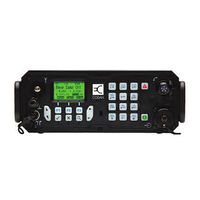
Codan 2110 series Reference Manual (521 pages)
Manpack Transceiver
Brand:
Codan
| Category:
Transceiver
| Size: 9.8 MB
Table of Contents
Table of Contents
3
1 About this Manual
17
Standards and Icons
19
Definitions
20
Acronyms and Abbreviations
20
Glossary
22
Units
27
Unit Multipliers
27
About this Issue
28
2 HF Radio Transmission
29
HF Radio Transmission
30
Figure 1: the Reflective Properties of the Ionosphere
30
Channels and Modes
31
Frequency, Distance and Time of Day
31
Table 1: Examples of Channels and Modes
31
Networks and Scanning
32
Etiquette for the Use of HF Radio
33
Table 2: the Phonetic Alphabet
34
3 The 2110 Series Manpack Transceiver
35
Figure 2: the 2110 Series Manpack Transceiver
36
The Front Panel
37
User Controls
37
Figure 3: the Front Panel (2110 Model Shown)
37
Interface Connectors
38
HF Antennas
38
Hot Keys
39
Table 3: Standard Hot Keys
39
Handset
41
Figure 4: the Handset
41
4 Preparing the Transceiver for Use
43
Charging a Battery Pack
44
Table 4: Typical Charging Times for Codan Battery Packs
44
Preparing the Transceiver for Use
44
Figure 5: Typical Front Panel of a Battery Charger
45
Table 5: LED Indications
45
Table 6: Cable Information for Battery Chargers
46
Care and Safety Information
48
Table 7: Storage Times of Battery Packs
48
Connecting a Battery to the Transceiver
49
Figure 6: Transceiver with Battery Pack Connected
49
Inserting the Transceiver into a Backpack
50
Figure 7: Transceiver in Backpack with Internal Frame
50
Selecting an Appropriate Tactical Antenna
51
Table 8: Selection Guide for Tactical Antennas
51
Table 9: Advantages and Limitations of a Tactical Whip Antenna
52
Table 10: Advantages and Limitations of a Tactical Long Wire Antenna and Adaptor
53
Table 11: Advantages and Limitations of a Tactical End-Fed Broadband Antenna
53
Table 12: Advantages and Limitations of a Tactical Broadband Dipole Antenna
54
Table 13: Advantages and Limitations of a Tactical Wire Dipole Antenna
54
Troubleshooting the Transceiver
55
Table 14: General Troubleshooting
55
Testing the Installation
56
Standing Wave Ratio
56
On-Air Testing
57
Using the 9350 Automatic Tuning Whip Antenna with a
59
5 Using the 9350 Automatic Tuning Whip Antenna with a 2110 Manpack Transceiver
60
Mobile Station
60
Figure 8: a 2110 Mobile Station Using Its Own Battery Pack
60
Figure 9: a 2110 Mobile Station Using a Vehicle's Battery
61
Automatic Tuning Whip Antenna
62
Table 15: Advantages and Limitations of the Automatic Tuning Whip Antenna
62
Installing the Transceiver
63
Positioning the Transceiver
63
Positioning the Antenna
64
Grounding the Antenna
64
Connecting the Antenna to the Transceiver
65
Power Supply
66
Table 16: Vehicle Battery Maintenance
66
Power Supply Factors
67
Installing the Cables
68
Connecting the Power Supply
69
Protecting the Cables
70
Radio Frequency Interference
71
Types of Noise
71
Noise from the Ignition System
71
Table 17: Noise Source and Type
71
Noise from the Vehicle's Battery-Charging System
72
Other Noise Sources
73
Noise Suppression
74
Tuning the Mobile Antenna (2110 Only)
75
Troubleshooting the Installation
76
Table 18: Possible Faults in the Installation
76
Testing the Installation
79
Standing Wave Ratio
79
On-Air Testing
80
6 Operating the Transceiver
81
6 Operating the Transceiver
82
Switching on the Transceiver
82
The Front Panel Screen
83
Figure 10: the Front Panel Screen
83
Figure 11: the Front Panel Screen Displaying a Value
83
The Channel Screen
84
Figure 12: the Channel Screen in the Channel List
84
Figure 13: the Scanning Screen
85
Battery Status Indicator
86
Figure 14: Battery Status Indicator
86
External Power Supply Indicator
87
Figure 15: External Power Supply Indicator
87
Selecting a Channel
87
Entering and Editing Text
88
The Editable Screens
88
Figure 16: Editable Screen Showing Upper-Case Text Entry
88
Figure 17: Editable Screen Showing Lower-Case Text Entry
88
Figure 18: Editable Screen Showing Numeric Text Entry
88
Editing a Screen
89
Figure 19: Editable Screen Showing Slider
89
Quick Start
94
Muting the Transceiver
99
Scanning Channels
100
Using the Microphone
102
Finding Words and Values
103
Setting the Basics
106
Setting the Time and Date
106
Displaying the Local Time and Date
108
Entering Your Station Self Address
108
Changing the Screen Contrast
112
Changing the Screen Brightness
112
Using Hot Keys
113
Tuning the Antenna
114
Automatic Tuning
114
Manual Tuning
115
Using the Clarifier
116
Reducing Background Noise with Easitalk
117
7 Using Lists
120
The Main Menu
120
Figure 20: the Contents of the Main Menu
120
Figure 21: Examples of Entries, Settings and Values
121
Selecting a List
122
The List Manager
123
Using the List Manager
123
Entries in the List Manager
124
Table 19: List Manager Entries and Their Functions
124
Setting a Marker
126
Setting the Home Screen
127
Changing a Setting in the Control List
128
Making Changes to All Other Lists
129
Saving Call Log Information to the Address List
132
Saving GPS Information to the Address List
134
Hiding and Showing Settings
135
Figure 22: the Address List with Settings Shown
135
Figure 23: the Address List with Settings Hidden
135
Grouping and Ungrouping Entries
137
Figure 24: Ungrouped Entries in a List
137
Figure 25: Grouped Entries in a List, Level One
137
Figure 26: Grouped Entries in a List, Levels One and Two
137
Figure 27: Ungrouped and Grouped Entries
138
Figure 28: Locking and Hiding Grouped Entries
141
Restricting Access to Information
142
Table 20: Restricting Access to Information at User and Admin Levels
143
Logging in to Admin Level
144
Displaying Full and Normal View
146
Figure 29: Full View
146
Hiding and Showing Information
147
Table 21: Hiding Items at User and Admin Levels
147
Locking and Unlocking Information
149
Table 22: Locking Items at User and Admin Levels
149
8 The Channel List
151
About Channels
152
Settings in the Channel List
152
Programming the Channel List
153
Editing a Channel
155
9 The Network List
157
About Networks
158
Figure 30: an Example of Information Stored in the Network List
159
Settings in the Network List
160
Table 23: Default Call Detect Times
161
Table 24: Nominal Preamble Times Calculated from Call Detect Time
163
Table 25: Default Nominal Preamble Times
163
Special Network Names
166
Programming the Network List
167
10 The NET List
172
About Nets
172
Figure 31: an Example of Information Stored in the NET List
173
Settings in the NET List
174
Programming the NET List
178
11 The Phone Link List
182
About Phone Links
182
Settings in the Phone Link List
182
Programming the Phone Link List
183
12 The Address List
185
About the Address List
186
Settings in the Address List
187
Setting up the Emergency Key
190
Calling One Station in an Emergency
190
Calling Several Stations in an Emergency
190
Figure 32: the Front Panel Screen During a Chain Call
192
Storing GPS Information in the Address List
194
Storing Your GPS Information in a Transceiver
194
Saving GPS Information
197
Programming the Address List
198
13 Making and Receiving Calls
201
Calls You Can Make and Receive
202
Special ALE Address Syntaxes
202
Table 26: Call Icons for Selective Calls Made or Received Using a Special ALE
202
Address Syntax
202
Summary of the Special ALE Address Syntaxes
208
Call Types
209
Table 27: Call Types and Icons
210
Emergency Call
211
Message Call
212
Selective Call
213
Group Calls in a Codan Selcall Network
214
Special AMD Messaging Features
215
Table 28: Special AMD Messaging Syntax
215
Recognised Variable Expansion
216
Table 29: Recognised Variables and Their Associated Information
216
Making a Call
218
Listen before Transmit Mode
218
Testing the Quality of a Channel in a Codan Selcall Network
219
Replacing LQA Information for All Channels in an ALE/CALM Network
220
Figure 33: LQA Screen Showing the most Recent Response
220
Making a Manual Sounding Operation in an ALE/CALM Network
222
Selecting the Best Channel in an ALE/CALM Network
223
Using Multiple Addresses for Calls in an ALE/CALM Network
224
Other Ways to Make Calls
225
Calling Methods
226
The Calls out Log
232
Figure 34: the Calls out Log Showing a Selective Call Made
232
Figure 35: the Calls out Log Showing a Message Call Made
232
Figure 36: the Calls out Log Showing a NET Call Made
233
Receiving a Call
235
Table 30: Call Types and Alert Tones
235
Figure 37: an Incoming Call Screen for a Selective Call
236
Figure 38: an Incoming Call Screen for a Message Call
236
Figure 39: an Incoming Call Screen for a NET Call
237
The Calls in Log
237
Figure 40: the Calls in Log Showing a Selective Call Received
238
Figure 41: the Calls in Log Showing a Message Call Received
238
Figure 42: the Calls in Log Showing a Get Status Call Received
238
Figure 43: the Calls in Log Showing a NET Call Received
239
Detecting Transmissions from Other Stations
241
Figure 44: the Last Heard Log
241
14 The Control List
243
Entries in the Control List
244
Table 31: Entries in the Control List
245
ALE Entries
257
Table 32: Settings for the ALE Site Mgr
264
Auto Resume Entries
266
Devices Entry
267
Figure 45: the Devices Entry in the Control List
267
Accessing Lists from the Devices Entry
273
Figure 46: Lists as They Are Displayed in the Main Menu and under the Devices
273
GPS Screen Entry
275
Figure 47: the GPS Screen Entry in the Control List
275
Table 33: Types of Readings on the GPS Screen
275
Displaying the Gps Screen
277
LQA Screen Entry
279
Figure 48: the LQA Screen Entry in the Control List
279
Messages Entry
280
RS232 Startup Entry
281
Table 34: Special Commands for the RS232 Startup Entry
281
Welcome Text
283
Table 35: Keywords that Display a Self Address
283
15 The Keypad List
285
Table 36: Entries in the Keypad List
285
16 The Mode List
287
Table 37: Possible Modes for the 2110 Manpack Transceiver
287
Table 38: Modes for the 2110V Manpack Transceiver
287
17 CES-128 Voice Encryptor Option
289
Overview
290
Using the CES-128 Voice Encryptor
292
Setting up the CES-128 Voice Encryptor
303
Figure 49: Example of a Text File Containing Secure Keys for Corporate Secure
305
Indexes
305
18 AES-256 Digital Voice Encryptor Option
309
Overview
310
Using the AES-256 Digital Voice Encryptor
311
Setting up the AES-256 Digital Voice Encryptor
318
Figure 50: Example of a Text File Containing AES Secure Keys
319
19 VP-116 Voice Encryptor Option
323
Overview
324
Using the VP-116 Unit
325
Switching off the VP-116 Unit
325
VP-116 Voice Encryptor Option
325
Selecting a New Encryption Key
326
Changing the Encryption Key While in Private Mode
326
Requesting a Public Encryption Key
327
Deleting All Encryption Keys in the VP-116 Unit
328
Automatic Startup of the VP-116
328
Automatic Startup of the
328
20 AES-256 Digital Data Encryptor Option
329
Overview
330
Setting up the Transceiver
331
Installing the Driver for the Cable
331
AES-256 Digital Data Encryptor Option
331
Connecting the Computer to the 2110
332
Figure 51: Computer Connected to the 2110
332
Figure 52: Computer Connected to the 2110 Via the Interface Adaptor
332
Using the AES-256 Digital Data Encryptor
334
Setting up the AES-256 Digital Data Encryptor
341
Using the AES-256 Digital Data Encryptor with a Voice Encryptor
342
Using the AES-256 Digital Data Encryptor with the AES-256 Digital Voice Encryptor
342
Using the AES-256 Digital Data Encryptor with the CES-128 Voice Encryptor
344
Operating the Data Modem
346
Uninstalling the Data Modem
346
21 Using the Transceiver in Free Tune and Amateur Mode
348
Using the Transceiver in Free Tune
348
Creating a Channel in Free Tune
351
Using the Transceiver in Amateur Mode
352
Table 39: Amateur Band Frequencies
352
22 Hot Keys
354
About Hot Keys
354
Full-Time and Part-Time Hot Keys
354
Table 40: Full-Time and Part-Time Hot Keys
354
Assigning Several Macros to One Key
355
Automating Several Tasks with One Macro
355
Troubleshooting Macros
355
Figure 53: Using a Hot Key to Which Several Macros Have Been Assigned
355
Storing Macros
356
Ideas for Creating Macros
356
Creating a Macro and Assigning It to a Hot Key
357
Table 41: Macro Options
359
Copying a Macro
360
Moving a Macro
361
Renaming a Macro
362
Deleting a Macro
362
Creating a Macro to Perform Two or more Tasks
363
Special Macros
365
Table 42: Macros Assigned to the Special Entry in the Keypad List
366
23 Connectors
367
Front Panel
368
Figure 54: Front Panel of the Transceiver (2110 Model Shown)
368
Connectors
368
Figure 55: Front View of the Handset Connector
369
Figure 56: Front View of the 19-Way GPIO Connector (2110 Only)
370
Table 44: Pinouts of the 19-Way GPIO Connector (2110 Only)
370
Figure 57: Front View of the External GPS Antenna Connector (2110 Only)
372
Table 45: Pinouts of the External GPS Antenna Connector (2110 Only)
372
Figure 58: Front View of the 5-Way Connector (2110V Only)
373
Table 46: Pinouts of the 5-Way Connector (2110V Only)
373
Back Panel
374
Figure 59: Back Panel of the Transceiver Unit
374
Figure 60: Front View of the Battery Connector on the Transceiver Unit
374
Table 47: Pinouts of the Battery Connector on the Transceiver Unit
374
Battery Pack
375
Figure 61: Connector Panel of the Battery Pack
375
Figure 62: Front View of the Battery Connector on the Battery Pack
375
Table 48: Pinouts of the Battery Connector on the Battery Pack
375
Interface Adaptor (2110 Only)
376
Pinouts of the Antenna Control Connector on the Interface Adaptor
376
Figure 63: Interface Adaptor
376
Figure 64: Front View of the Antenna Control Connector on the Interface Adaptor
376
Table 49: Pinouts of the Antenna Control Connector on the Interface Adaptor
376
Pinouts of the Speaker Connector on the Interface Adaptor
377
Table 50: Pinouts of the Speaker Connector on the Interface Adaptor
377
Pinouts of the 15-Way GPIO Connector on the Interface Adaptor
378
Figure 65: Front View of the 15-Way GPIO Connector on the Interface Adaptor
378
Table 51: Pinouts of the 15-Way GPIO Connector on the Interface Adaptor
378
Pinouts of the 15-Way VP-116 Connector on the Interface Adaptor
381
Figure 66: Front View of the 15-Way VP-116 Connector on the Interface Adaptor
381
Table 52: Pinouts of the 15-Way VP-116 Connector on the Interface Adaptor
381
24 System Messages
383
Table 53: System Messages
384
25 Specifications
397
Table 54: Specifications for the 2110 Series Manpack Transceiver
397
Table 55: Specifications for the GPS Connector
399
Table 56: Specifications for the Internal RM50 HF Data Modem
400
Accessories
401
Table 57: Physical Specifications of Accessories
401
Appendix A Hot Key Examples
404
Example 1: Selecting a Specific Channel
404
Example 2: Displaying an Information Screen
405
Example 3: Displaying And/Or Changing a Setting in the Control List
406
Example 4: Changing a Value to the Next Value in a List
407
Example 5: Opening a List at the Marker Entry
408
Example 6: Making a Call Using a Specific Entry in the Address List
409
Example 7: Setting up One-Touch Discreet Operation
410
Appendix B Get Status Calls
411
Diagnostic and Configuration Get Status Calls
411
Table 59: Information Retrieved in a Codan Diagnostic Get Status Call Made to
412
Table 60: Information Retrieved in an Open Diagnostic Get Status Call
413
To a Codan HF Transceiver
414
To a Codan 9323 or 9360 Transceiver
415
Broadcast Site and Request Site Get Status Calls
416
Appendix C Forgotten Passwords
420
About CICS
420
Appendix D Operating the Transceiver from a Computer
420
Using CICS
420
Special Characters
421
Table 64: Variable Expansion in a Command
424
Setting up CICS
427
Table 65: CICS Commands and the Equivalent 2110 Manpack Transceiver Terms
428
Terms Used in CICS and the 2110 Manpack Transceiver
428
CICS Commands
429
Table 66: CICS Commands and Their Functions
429
Alebeacon Command
431
Alecall Command
432
Aletelcall Command
433
Amd Command
434
Beacon Command
435
Call Command
436
Chan Command
437
Echo Command
438
Freq Command
439
Gpsbeacon Command
440
Gpsposition Command
441
Hangup Command
441
Help Command
442
Lbt Command
442
Link Command
443
Lock Command
443
Lqa Command
444
Mode Command
445
Mute Command
445
Pagecall Command
446
Table 67: Variations in Message Length
446
Prompt Command
447
Ptt Command
448
Scan Command
449
Secure Command
450
Selbeacon Command
452
Selcall Command
453
Selfid Command
454
Set Command
455
Sideband Command
456
Sound Command
457
Statusack Command
458
Statuscall Command
459
Statustime Command
460
Telcall Command
461
Ver Command
461
Summary of Command Syntax
462
Table 68: Summary of CICS Command Syntax
462
CICS Response Messages
466
Table 69: CICS Response Messages
466
CICS Error Messages
470
Table 70: CICS Error Messages
470
Table 71: Compatibility Issues between CICS V2 and V3.00 (or Later)
477
Appendix E Compatibility between CICS V2 and V3.00 (or Later)
478
Using = and
478
Table 72: Symbols Used in CICS V2
478
Using Channel Names or Channel Numbers
479
Using Scan Tables or Networks
479
Using Upper-Case or Lower-Case Text
480
Using Quotation Marks
480
Using Addresses with or Without a Network
481
Appendix F Controlling User Access
484
Introduction
484
Syntax for the Message 10 Entry
485
Activating Configuration Commands in the Message 10 Entry
485
Controlling Access to the List Manager
486
Table 73: Codes for Controlling Access to the List Manager
488
Controlling Access to Admin Level
489
Controlling Access to Call Types
490
Table 74: Codes for Controlling Access to Call Types from the Front Panel
490
Controlling Access to Holding CALL
491
Controlling Access to Creating a Channel in Free Tune
491
Controlling Access to CES-128 Voice Encryptor Options
492
Controlling Access to AES-256 Digital Voice and Data Encryptor Options
495
Table 77: Codes for Controlling Access to AES-256 Digital Voice and Data
496
Controlling Access to Erasing Secure Keys
497
Enabling Medium Power Level
497
Enabling the Automatic Removal of the Incoming Call Pop-Up
497
Table 78: Code for Controlling Access to Erasing Secure Keys
497
Enabling GPS Format Options
498
Table 79: Codes for Enabling GPS Format Options
498
Enabling User Interface Options
499
Table 80: Codes for Enabling User Interface Options
499
Enabling Access to Site Manager Information
500
Table 81: Codes for Enabling Access to Site Manager Information
500
Enabling Priority Messaging Options
502
Table 82: Codes for Enabling Priority Messaging Options
502
Appendix G Compliance
505
Introduction
506
European R&TTE Directive
506
EMC and Safety Notices
507
Table 83: Earth Symbol
508
FCC Compliance
509
C-Tick Approval
509
Index
511
Advertisement
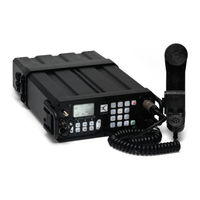
Codan 2110 series Repair Manual (164 pages)
Manpack Transceiver
Brand:
Codan
| Category:
Transceiver
| Size: 5.86 MB
Table of Contents
Table of Contents
3
Index
11
Introduction
15
Overview of this Guide
15
How to Use this Guide
16
Board Replacement Philosophy
16
Disposal
16
Circuit Board Precautions
17
Transmitter Precautions
18
Probe Precautions
18
Contact Information
19
Ordering Information
21
Overview
23
General
24
Figure 1: the 2110 Series Manpack Transceiver
24
Connectors
25
Front Panel
25
Figure 3: Front View of the Handset Connector
26
Table 1: Pinouts of the Handset Connector
26
Figure 5: Front View of the 19-Way GPIO Connector (2110 Only)
28
Table 3: Pinouts of the 19-Way GPIO Connector (2110 Only)
28
Back Panel
30
Figure 7: Back Panel of the Transceiver Unit
30
Battery Pack
32
Figure 9: Front View of the Battery Pack
32
Figure 10: Front View of the Battery Connector on the Battery Pack
32
Table 6: Pinouts of the Battery Connector on the Battery Pack
32
Brief Description
34
General Information
37
Transmit Path
38
Front Panel PCB
38
Audio & Control PCB
38
RF/IF & Synthesiser PCB
39
PA & Filter PCB
39
Receive Path
39
Antenna Tuner PCB
39
Audio & Control PCB
39
Antenna Tuning Process
40
Synthesiser Operation
40
Control and Switching
40
Interconnection Diagrams and Listed Spares Drawings
41
Table 7: List of Drawings
41
Figure 2: Front Panel of the Transceiver (2110 Model Shown)
43
Figure 4: Front View of the External GPS Antenna Connector (2110 Only)
45
Figure 6: Front View of the 5-Way Connector (2110V Only)
47
Figure 8: Front View of the Battery Connector on the Transceiver Unit
49
Figure 11: RF/IF & Synthesiser PCB (08-06039-001)
62
Figure 12: PA & Filter PCB (08-06064-001)
62
Figure 13: Audio & Control PCB (08-06128-001)
64
Figure 14: Antenna Tuner PCB (08-06063-001)
64
Figure 15: Front Panel PCB (08-06129-001)
64
Table 8: Test Points for the RF/IF & Synthesiser PCB (08-06039-001)
66
PA & Filter PCB
69
Table 9: Test Points for the PA & Filter PCB (08-06064-001)
70
Audio & Control PCB
72
Table 10: Test Points for the Audio & Control PCB (08-06128-001)
74
Antenna Tuner PCB
76
Front Panel Assembly
78
Front Panel PCB
80
Repair Procedures, Tests, and Adjustments
83
Test Equipment
84
Figure 16: Setup for Artificial Antenna
85
Figure 17: Setup for RF Sampler
85
Table 13: Test Equipment
85
Setup of Test Equipment for 2110
86
Figure 18: Setup for 2110
86
Repair Procedures and Fault Diagnosis
87
General
87
Figure 19: Balance Control on the 0208
89
Mechanical Inspection
90
Operational Tests
91
Table 15: Default Settings for the Transceiver During Testing
92
Receive Tests
95
Transmit Tests
100
Table 16: 20/25 W Output Power Scale
103
Table 17: 4/5 W Output Power Scale
104
Figure 20: Acceptable Two-Tone RF Envelope
105
Figure 21: Defective Two-Tone RF Envelope (Typical Overbias of PA)
105
Figure 22: Defective Two-Tone RF Envelope (Typical Underbias of PA)
106
Figure 23: Defective Two-Tone RF Envelope (Typical Spurious-Related Problems)
106
Figure 24: Intermodulation Measurements Using a Spectrum Analyser
107
Disassembling the Transceiver
109
Figure 25: Removing the Housing from the Chassis
109
Adjustments
111
Adjusting Frequency
111
Adjusting the PA
111
Re-Assembling the Transceiver
115
Figure 26: Setup for Vacuum Test
116
Checking the Battery Charging Process
118
Figure 27: Typical Front Panel of a Battery Charger
119
Replacing Battery Cells
122
Figure 28: Connections between the Battery Cells and the Battery Monitor PCB
122
Replacing the Fuse in the Battery Pack
123
Flowcharts
125
Figure 29: Repair Flowchart
127
Figure 30: Disassembly Flowchart
129
Figure 31: Power on Fault Diagnosis Flowchart
131
Figure 32: Receive Fault Diagnosis Flowchart 1
133
Figure 33: Receive Fault Diagnosis Flowchart 2
135
Figure 34: Transmit Fault Diagnosis Flowchart 1
137
Figure 35: Transmit Fault Diagnosis Flowchart 2
139
Test Sheet for the 2110 Series Manpack Transceiver
141
Figure 36: GPS Receiver
147
Figure 37: Connector for External GPS Antenna
148
Table 20: Front Panel Assembly and Final Assembly with GPS Connector
148
Figure 38: Voice Encryptor
149
Figure 39: Filters
149
Standards and Icons
151
Definitions
152
Acronyms and Abbreviations
152
Glossary
154
Circuit Reference Designations
155
Units
156
Unit Multipliers
156
About this Issue
157
Specifications
159
General
159
Table 21: General Specifications
159
Receiver
161
Table 22: Receiver Specifications at 50 Antenna Connector
161
Transmitter
162
Antenna Tuner
163
GPS Connector
163
Codan 2110 series Reference Manual (142 pages)
SSB
Brand:
Codan
| Category:
Transceiver
| Size: 3.04 MB
Table of Contents
Table of Contents
3
1 About this Manual
13
Standards and Icons
15
Definitions
16
Acronyms and Abbreviations
16
Glossary
18
Units
22
Unit Multipliers
22
About this Issue
23
2110 SSB Transceiver Compliance
26
Introduction
26
European Radio and Telecommunications Terminal Equipment Directive
27
Electromagnetic Compatibility and Safety Notices
28
Table 1: Earth Symbol
29
C-Tick Approval
30
Care and Safety Information
31
Table 2: Battery Storage Times
31
3 HF Radio Transmission
33
HF Radio Transmission
34
Figure 1: the Reflective Properties of the Ionosphere
34
Channels and Modes
35
Frequency, Distance and Time of Day
35
Table 3: Examples of Channels and Modes
35
Networks and Scanning
36
Etiquette for the Use of HF Radio
37
Table 4: the Phonetic Alphabet
38
4 The 2110 SSB Transceiver
39
Figure 2: the 2110 SSB Transceiver
39
The Front Panel
40
User Controls
40
Figure 3: the Front Panel
40
Interface Connectors
41
Antennas
41
Hot Keys
42
Table 5: Standard Hot Keys
42
Figure 4: the Handset
44
Handset
44
5 Preparing the 2110 SSB Transceiver for Use
46
Charging a Battery
46
Figure 5: Typical Front Panel of a Battery Charger
46
Connecting a Battery to the Transceiver
48
Inserting the Transceiver into a Backpack
48
Figure 6: Transceiver with Battery Pack Connected
48
Selecting an Appropriate Antenna
49
Table 6: Selection Guide for Antennas
49
Table 7: Advantages and Limitations of a Vertical Whip Antenna
50
Table 8: Advantages and Limitations of a Long Wire Antenna and Adaptor
51
Table 9: Advantages and Limitations of a End-Fed Broadband Antenna
51
Table 10: Advantages and Limitations of a Broadband Dipole Antenna
52
Table 11: Advantages and Limitations of a Wire Dipole Antenna
52
Troubleshooting the Transceiver
53
Table 12: General Troubleshooting
53
Testing the Installation
54
Voltage Standing Wave Ratio
54
On-Air Testing
55
6 Operating the Transceiver
57
Switching on the Transceiver
58
The Front Panel Screen
59
Figure 7: the Front Panel Screen
59
Figure 8: the Front Panel Screen Displaying a Value
59
The Channel Screen
60
Figure 9: the Channel Screen in the Channel List
60
Figure 10: the Scanning Screen
61
Battery Status Indicator
62
Figure 11: Battery Status Indicator
62
External Power Supply Indicator
63
Figure 12: External Power Supply Indicator
63
Selecting a Channel
63
Entering and Editing Text
64
The Editable Screens
64
Figure 13: Editable Screen Showing Upper-Case Text Entry
64
Figure 14: Editable Screen Showing Lower-Case Text Entry
64
Figure 15: Editable Screen Showing Numeric Text Entry
64
Editing a Screen
65
Figure 16: Editable Screen Showing Slider
65
Quick Start
69
Muting the Transceiver
73
Scanning Channels
74
Using the Microphone
75
Finding Words and Values
76
Setting the Basics
79
Setting the Time and Date
79
Displaying the Local Time and Date
81
Entering Your Station Self Address
81
Changing the Screen Contrast
86
Changing the Screen Brightness
86
Using Hot Keys
87
Tuning the Antenna
88
Automatic Tuning
88
Manual Tuning
89
Using the Clarifier
90
Reducing Background Noise with Easitalk
91
Using the Voice Encryptor
92
Setting up the Voice Encryptor
96
7 Using Lists
99
The Main Menu
100
Figure 17: the Contents of the Main Menu
100
Figure 18: Examples of Entries, Settings and Values
101
Selecting a List
102
The List Manager
103
Using the List Manager
103
Entries in the List Manager
104
Table 13: List Manager Entries and Their Functions
104
Setting a Marker
106
Setting the Home Screen
107
Changing a Setting in the Control List
108
Making Changes to All Other Lists
109
Hiding and Showing Settings
113
Figure 19: the Address List with Settings Shown
113
Figure 20: the Address List with Settings Hidden
113
Grouping and Ungrouping Entries
115
Figure 21: Ungrouped Entries in a List
115
Figure 22: Grouped Entries in a List, Level One
115
Figure 23: Grouped Entries in a List, Levels One and Two
115
Figure 24: Ungrouped and Grouped Entries
116
Figure 25: Locking and Hiding Grouped Entries
119
Restricting Access to Information
120
Table 14: Restricting Access to Information at User and Admin Levels
121
Logging into Admin Level
122
Displaying Full and Normal View
124
Figure 26: Full View
124
Hiding and Showing Information
125
Table 15: Hiding Items at User and Admin Levels
125
Locking and Unlocking Information
127
Table 16: Locking Items at User and Admin Levels
127
8 The Channel List
129
About Channels
130
Settings in the Channel List
130
Programming the Channel List
131
Editing a Channel
132
9 The Network List
134
About Networks
134
Figure 27: an Example of Information Stored in the Network List
134
Settings in the Network List
135
Special Network Names
139
Programming the Network List
140
The Control List
141
Advertisement
Codan 2110 series Getting Started Manual (101 pages)
Manpack Transceiver
Brand:
Codan
| Category:
Transceiver
| Size: 1.3 MB
Table of Contents
Table of Contents
3
Overview of this Guide
11
Accessing the CD
12
2110 Series Manpack Transceiver Compliance
13
Introduction
14
European Radio and Telecommunications Terminal Equipment Directive
15
Electromagnetic Compatibility and Safety Notices
17
Table 1: Earth Symbol
19
FCC Compliance
20
C-Tick Approval
21
Care and Safety Information
22
Table 2: Storage Times for Battery Packs
22
2 Your 2110 Series Manpack Transceiver
25
3 Preparing the Transceiver for Use
29
Charging a Battery Pack
30
Figure 1: Typical Front Panel of a Battery Charger
31
Table 3: Typical Charging Times for Codan Battery Packs
31
Table 4: LED Indications
32
Connecting a Battery Pack to the Transceiver
37
Figure 2: Transceiver with Battery Pack Connected
37
Inserting the Transceiver into a Backpack
38
Selecting an Appropriate Tactical Antenna
39
Table 5: Selection Guide for Tactical Antennas
39
4 The Front Panel
41
Overview
41
Figure 3: the Front Panel (2110 Model Shown)
41
User Controls
42
Antennas
43
Interface Connectors
43
Hot Keys
44
Table 6: Standard Hot Keys
44
The Channel Screen
46
Figure 4: the Channel Screen in the Channel List
46
Battery Status Indicator
47
Figure 5: Battery Status Indicator
47
The Handset
49
Figure 6: the Handset
49
5 Getting Started
52
Switching on the Transceiver
52
Switching off the Transceiver
52
Setting up Basics
53
Selecting a Channel
54
Making a Basic Voice Call
55
Making a Selective Call
56
Scanning Channels
59
Switching Scanning on or off
59
Pausing Scanning
60
6 Troubleshooting
61
Table 7: General Troubleshooting
62
Appendix A-Entering and Editing Text
63
Editing a Screen
63
Entering Text
64
Changing between Alpha and Numeric Characters
65
Moving the Cursor
65
Inserting Text
66
Deleting Text
66
Saving Text Changes
66
Appendix B-Using Quick Start
67
Appendix C-Using a GPS Receiver
75
Appendix D-Transceiver Specifications
77
Table 8: 2110 Series Manpack Transceiver Specifications
77
Appendix E-Hf Radio Transmission
79
Frequency, Distance and Time of Day
80
Figure 7: the Reflective Properties of the Ionosphere
80
Antenna Selection
81
Channels and Modes
81
Networks and Scanning
82
Table 9: Examples of Channels and Modes
82
Etiquette for the Use of HF Radio
83
Table 10: the Phonetic Alphabet
84
Appendix F-Definitions
85
Standards and Icons
85
Acronyms and Abbreviations
86
Glossary
88
Units
93
Unit Multipliers
94
About this Issue
95
Appendix G-Warranties
97
Index
99
Codan 2110 series Getting Started Manual (90 pages)
HF Radio Communications SSB Transceiver
Brand:
Codan
| Category:
Transceiver
| Size: 1.16 MB
Table of Contents
Overview of this Guide
11
Accessing the CD
12
1 2110 SSB Transceiver Compliance
13
Introduction
14
Directive
15
Electromagnetic Compatibility and Safety Notices
17
Electrical Safety
18
C-Tick Approval
19
Care and Safety Information
20
2 Your 2110 SSB Transceiver
23
3 Preparing the 2110 SSB Transceiver for Use
25
Charging a Battery
26
Connecting a Battery to the Transceiver
29
Inserting the Transceiver into a Backpack
30
Selecting an Appropriate Antenna
31
Overview
33
User Controls
34
Interface Connectors
35
Hot Keys
36
The Channel Screen
38
Battery Status Indicator
39
The Handset
41
Switching on the Transceiver
44
Setting up Basics
45
Selecting a Channel
46
Making a Basic Voice Call
47
Making a Selective Call
48
Scanning Channels
51
6 Troubleshooting
53
Editing a Screen
55
Entering Text
56
Changing between Alpha and Numerical Characters
57
Deleting Text
58
Specifications
67
Frequency, Distance and Time of Day
70
Antenna Selection
71
Networks and Scanning
72
Standards and Icons
75
Acronyms and Abbreviations
76
Glossary
78
Units
82
About this Issue
83
Advertisement
Related Products
Codan 2110v
Codan 5700 series
Codan 5705
Codan 5710
Codan 5712H
Codan 5720
Codan 5730
Codan 5740
Codan 5760
Codan 8525
Codan Categories
Transceiver
Radio
Receiver
Modem
Antenna
More Codan Manuals
Login
Sign In
OR
Sign in with Facebook
Sign in with Google
Upload manual
Upload from disk
Upload from URL