Sign In
Upload
Manuals
Brands
Coastcom Manuals
Multiplexer
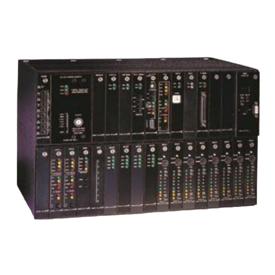
D/I Mux III System
Coastcom D/I Mux III System Manuals
Manuals and User Guides for Coastcom D/I Mux III System. We have
1
Coastcom D/I Mux III System manual available for free PDF download: User Manual
Coastcom D/I Mux III System User Manual (329 pages)
For D/I Mux III Shelf and Common Equipment
Brand:
Coastcom
| Category:
Multiplexer
| Size: 3.8 MB
Table of Contents
Design Compliance
7
FCC Part 68 Requirements
9
FCC Requirements for Connection of Systems to the Telephone Network
9
Federal Communications Commission (FCC)
9
Part 15 Regulations for Telephone Equipment
9
Safety Agency Certifications
12
Table of Contents
13
Chapter 1. System Overview and Modes of Operation
21
D/I Mux III Capabilities
21
D/I Mux III Functions
22
D/I Mux III Features
22
D/I Mux III Software Control
23
Remote Control with NCC
24
Snmp
24
Serial Line Internet Protocol (SLIP)
26
Gateway
27
Transmission Control
27
Transmission Channel Assignments
28
Maps
28
Timing and Clock Source
29
Alarms and Monitoring
29
Power Failure Alarm
30
Alarm LED Indicators, Alarm Cut-Off, and Bypass
30
Power Supply Failure Indicator Leds
30
Minor Alarm
30
Bypass
30
Trunk Processing
31
T1 Interfaces - Csus
31
Lightning Protection
31
T1 Testing with the CSU
31
Power Supplies
32
-48 Volt DC Power Supplies
32
110 Volt AC Power Supply
32
D/I Mux III User Circuit Interfaces
33
Circuit Features
34
Component Overview
35
Shelves
37
Shelf Backplane Connectors
38
Common Equipment Units and Line Cards
39
Common Equipment
39
Common Control Unit
39
CCU Circuit Description
41
Advanced Multiplexer Control Unit (AMCU)
42
AMCU Motherboard Circuit Description
42
AMCU Sub-Board Circuit Description
46
Strobe Units
50
Line Interface Units
52
T1 Interface Units
54
Power Supplies
55
Line Cards
55
Data Line Cards
55
Voice Line Cards
56
Digital Program Line Cards
56
Modes of Operation
57
Channel Bank Operation
57
Loop Timing
57
Local Timing
57
Drop-And-Insert Operation
58
Recovered Timing
58
Dual Channel Bank Operation
58
Loop Timing
59
Local Timing
59
Chapter 2. Applications
60
Channel Bank
60
Point-To-Public Network
60
Point-To-Point Private Network
61
Drop-And-Insert
63
Sharing Switch and FXS Applications
63
Dropping Data - Polled Data Network
63
Dual Channel Bank
64
Voice, Video, and Special Services Networks
64
Chapter 3. Installation
65
Equipment Location
65
Space Requirements
65
Shelves
66
Access Requirements
66
Power Requirements and Capacity
66
-48 VDC Power Systems
67
-24 V DC Power Systems
67
110 VAC Power Systems
67
Required Equipment for D/I Mux III Installation
67
Shelf Installation
68
Rack and Cabinet Installation
68
Desktop
69
Wall Mounting
70
System Cabling
74
FCC Radio Frequency Emission Compliance
74
Power and Alarms
80
Talk Battery
80
DC Power
80
AC Power
81
Alarm Contacts
81
T1 Transmission Lines
81
T1 Cabling Considerations
83
Timing Sync I/O
84
Slot 2 Synchronization (Optional)
85
Event Switch
86
Voice and Data Connections
86
Voice or Data Jumpers
86
Voice Circuits
87
Data Circuits
93
Digital Program Channels
94
Common Equipment and Line Card Installation
94
Electrostatic Precautions
94
Safety Precautions
95
Installing Cards in Shelf
95
Removing Cards from Shelf
95
Strobe Units
97
Common Control Unit
98
Advanced Multiplexer Control Unit (AMCU)
99
Line Interface Units
104
T1 Interfaces
106
Power Supply
110
Heat Considerations
110
DC Power Unit (P/N 30338-102 and 30338-902)
113
110 V AC Power Unit
115
Smart 110 V AC Power Supply
117
Transmission Connection
119
Cable
119
Line Card Installation
120
System Power-Up and Initialization
120
Configuring the D/I Mux III System
120
Chapter 4. Configuration and Operation
121
Setup and Programming Order
123
Screen Display and Data Entry
124
Obtaining System Access
125
AC - Accessing the CCU/D/I Mux III User Screen
128
AMCU Configuration
129
CL - Copying Line Card Configuration
129
CM - Copying the Map Matrix
131
DA - Displaying Alarms
132
DC - Displaying Shelf Configuration
133
DD - Displaying Line Card Data Configuration
134
DH - Displaying Alarm History
135
DM - Displaying Map Matrix
137
DN - Displaying the Current Working Map
139
DP - Displaying System Parameters
139
DS - Displaying Clock Source
140
DT - Displaying the Current Map Table
141
DV - Displaying Smart AC Power Supply Parameters
142
DW - Displaying the Current Password
143
EW - Erasing Passwords
143
LO - Logging off
144
MC - Modifying the CCU - Downloading Code
144
MG - Modifying/Setting the Gateway Address
145
MI - Modifying/Setting the Local IP Address
146
ML - Modifying/Setting SLIP Parameters
147
MM - Modifying/Installing the Manager
148
MP - Modifying/Installing an MCU Password
149
MS - Modifying/Installing the Subnet Mask
150
OD - Operate Diagnostics Menu
152
OL - Operate Line Card Diagnostics Menu
153
PM - FDL Monitor
155
Q - Quit Command
156
RM - Removing the Manager
156
RP - Removing/Erasing Passwords
157
SB - Setting the Error Rate
157
SC - Setting Shelf Configuration
159
SL - Setting Line Card Configuration
164
SM - Setting/Editing a Map Matrix
165
SN - Setting the Working Map
168
SO - Setting the Communications Configuration
169
SP - Setting System Operation Parameters
169
SR - Setting the COM Port Data Rate
172
SS - Setting the Clock Source
173
ST - Setting/Editing the Map Table
174
SW - Setting/Installing CCU Passwords
175
VM - Viewing Manager Configuration
177
VN - Viewing Network Parameters
177
VP - Viewing Passwords
178
VR - Viewing Software Revision Status
179
ZA - Clearing Alarm Count
180
ZH - Clearing Alarm History
180
Chapter 5. Diagnostics
181
Test Records
181
T1 Alarms
182
Local Alarm
182
Yellow Alarm
182
Carrier Group Alarm
182
Frame Alarm
182
B7 Alarm
183
BPV Alarm
183
0-DEN Alarm
183
Loop Codes Alarms
183
Alarm Contacts
183
Alarm Dialout
184
ACO Button
184
Bypass Button
184
Bypass
184
Power-Up Sequence
185
Troubleshooting
185
System-Level Troubleshooting
187
Board-Level Troubleshooting
187
Common Equipment and Line Card Testing
188
Defective Units
188
Line Interface Units (Lius)
189
T1 Transmission Tests
191
T1 Interfaces
191
Single Channel Bank Mode
195
Drop-And-Insert Mode Tests
197
Software Controlled Loopback Tests
198
Loopback Tests
199
Channel Bank: Normal Operation
199
Channel Bank: Bypass
200
Channel Bank: Line Loopback
201
Channel Bank: Payload Loopback
202
Drop-And-Insert: Normal Operation
203
Drop-And-Insert: Bypass
204
Drop-And-Insert: Line Loopback
205
Drop-And-Insert: Payload Loopback
208
Dual Channel Bank: Normal Operation
210
Dual Channel Bank: Bypass
210
Dual Channel Bank: Line Loopback
211
Dual Channel Bank: Payload Loopback
214
Software Diagnostics
216
OL - Operate Line Card Diagnostics
216
OD - Operate Diagnostics
217
Performance
220
SB - Set Bit Error Rate Options
221
Technical Assistance
221
D/I Mux III Messages
222
Alarm Reporting
225
Appendix A. D/I Mux III Specifications
228
Appendix B. -24 Volt Systems
233
Common Equipment
233
Voice Cards
233
Appendix C. - Accessories Installation
235
Card Extender
235
External AC Power Supply
235
Installing the External AC Power Supply
235
Ringing Generator
236
Installing the Ringing Generator
236
Appendix D. Preconfigured Maps
238
Strobe Option Switch #1 - 24-Card Slots: 64 Kbps Per Slot
239
Strobe Option Switch #2 - 12-Card Slots: Two 64 Kbps Per Slot
240
Strobe Option Switch #3 - 12-Card Slots: 128 Kbps Per Slot
241
Strobe Option Switch: #4 - 8-Card Slots: 192 Kbps Per Slot
241
Strobe Option Switch #5 - 6-Card Slots: 256 Kbps Per Slot
242
Strobe Option Switch #6 - 4-Card Slots: 384 Kbps Per Slot
242
Strobe Option Switch #7 - 3-Card Slots: 512 Kbps Per Slot
242
Strobe Option Switch #8 - 1-Card Slot: 1.536 Kbps Per Slot
242
Appendix E. Snmp
244
Appendix F. Mib II and Ds1 Mib Group Names and Objects
246
Appendix G. Modem Interfaces
266
General Modem Operation
266
Hayes Command Set
266
Special Coastcom Characters
266
NCC Characters
266
D/I Mux III Characters
267
DXC II Characters
267
Hayes 1200 and 1200B Command Sets
270
Smartmodem 2400/2400B Command Set
271
V-Series Commands
274
Modem Considerations
277
Line Noise
277
Command Timing
277
Modem-To-Modem Sequencing
277
Modem Control Lines
277
Dial-Out Call Processing
277
Modems and the NCC System
278
Making Connection
278
Processing Messages
279
Terminating Connection
280
Modems and D/I Mux III or DXC II Systems
281
Making Connection
281
Connection Stabilization
282
Processing Messages
282
Terminating Connection
282
Appendix H. Set Report Options
285
Setting Communications in Terminal Mode with Inaudible Terminal Alarm Reporting
286
Feature Group 6.0/6.2 Screen Changes
286
Setting Communications in Terminal Mode with Modem Dial-Out
288
Feature Group 6.0/6.2 Screen Changes
288
Setting Communications in Terminal Mode with Alarm Reporting off
290
Feature Group 6.0/6.2 Screen Changes
290
Setting Communications in MML Mode with Modem Dial-Out Enabled
292
Feature Group 6.0/6.2 Screen Changes
292
Setting Communications in MML Mode with Modem Dial-Out Disabled
294
Feature Group 6.0/6.2 Screen Changes
294
Displaying Modem and Port Expander Information
296
Feature Group 6.0/6.2 Screen Changes
297
Configuring the Modem
298
Displaying New Modem Configuration
300
Configuring the Port Expander
301
Displaying New Port Expander Configuration
303
Quitting Alarm Reporting Configuration
304
Appendix I. Traps and Modem Dial out Configuration
306
AMCU New Screens
306
Hardware Warranty and 90-Day Support Agreement
329
Advertisement
Advertisement
Related Products
Coastcom Categories
Multiplexer
Touch terminals
More Coastcom Manuals
Login
Sign In
OR
Sign in with Facebook
Sign in with Google
Upload manual
Upload from disk
Upload from URL