Sign In
Upload
Manuals
Brands
Chrysler Manuals
Engine
LM 318
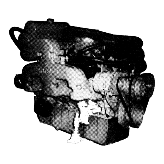
User Manuals: Chrysler LM 318 Boat Engine
Manuals and User Guides for Chrysler LM 318 Boat Engine. We have
1
Chrysler LM 318 Boat Engine manual available for free PDF download: Service Manual
Chrysler LM 318 Service Manual (123 pages)
Brand:
Chrysler
| Category:
Engine
| Size: 15.83 MB
Table of Contents
Contents
3
Identification
5
Service Bulletins
5
Engine Rotation Decal
5
Propeller Rotation Decal
5
Preparation of New Engine for Operation
6
Pre-Starting Inspections
6
Starting and Stopping Engine
6
Operating Precautions
6
Breaking in a New or Rebuilt Engine
7
Oil Pressure
7
Water Temperature
7
Engine Data and Specifications
8
Tool List
17
Cooling System
18
Proper Belt Tension
18
Raw Water System
18
Raw Water Pump (Disassembled View)
19
Fresh Water System
20
Cooling System Diagram Raw Water/Center Rise Manifold
21
Thermostat Open/Closed
21
Cooling System Diagram F.w.C./Center Rise Manifolds
22
Fresh Water Circulating Pump
23
Removing Impeller and Metal Insert
23
Removing Pulley Hub
23
Selection of Lubricant
24
Materials Added to Engine Oils
24
Engine Oil Filter
24
Full-Flow Oil Filter
24
Close Crankcase Ventilation System
25
Lubrication and Maintenance Schedule
26
Checking Operation of Exhaust Valve Rotators
28
Rocker Arms and Shaft Assembly
28
Cylinder Heads
29
Valves and Valve Springs
30
Intake Manifold Sealing
30
Intake Manifold Screw Tightening Sequence
30
Compressing Valve Spring
30
Valve Inspection
31
Refacing Valves and Valve Seats
31
Position Valve with Tool C-3973
31
Measuring Valve Guide Wear
31
Valve Seats
32
Testing Valve Springs
32
Valve Face and Seat Angles
32
Refacing Engine Valve Seats
32
Checking Valve Spring for Squareness
33
Measuring Valve Stem Length with Tool C-3968
33
Installing Valve, Cup Seal, Spring and Retainer
33
Hydraulic Tappets
34
Tappet Noise Diagnosis
34
Tappet Removal
34
Oil Level too High/Low
34
Valve Timing
35
Timing Chain Cover, Oil Seal and Chain
35
Timing Chain Cover External Oil Seal
36
Alignment of Timing Marks
36
Measuring Timing Chain for Stretch
36
Camshaft
37
Installing Oil Seal
37
Removing Oil Seal
37
Camshaft Bearings
39
Distributor Drive Shaft Bushing
39
Timing Chain Oil Tab Installation
39
Removal and Installation of Camshaft Bearings with Tool C-3132A
39
Cylinder Block
40
Engine Core Oil and Cam Plugs
41
Piston Pins
41
Pistons, Pins and Rings
41
Crankshaft Identification
42
Installing Piston and Connecting Rod Assembly
43
Crankshaft Main Journals
43
Connecting Rods
43
Crankshaft Main Bearings
43
Rear Main Bearing Oil Seals
44
Engine Oiling System
46
Oil Pan
47
Oil Pump
47
Oil Line Plug
48
Oil Filter
49
Removing Oil Filter with Tool C-4065
50
Fuel System-Rochester Quadrajet Carburetor
51
Operating Systems
52
Float System
52
Idle System
53
Off-Idle Operation
53
Main Metering System - 4MV
54
Adjustable Part Throttle Feature 4MV
54
Pull-Over Enrichment (P.O.E.)
55
Power System
55
Adjustable Part Throttle Feature
55
Power System - Mechanical Operation
56
Multiple Stage Power Enrichment
56
Auxiliary Power Piston
56
Main (Primary) Power Piston
57
Secondary System
57
Metering Rods - Primary
58
Metering Rods - Secondary
58
Air Valve Dashpot
58
Accelerating Pump System
59
Major Service Operations - All Models
60
Choke System
60
Pump Stem Seal and Retainer
60
Air Horn Removal
61
Typical Quadrajet Carburetor
61
Removing Upper Choke Lever
61
Removing Secondary Metering Rods
62
Pump Lever Removal
62
Air Horn Screw Removal
62
Air Horn Disassembly
63
Float Bowl Assembly
63
Auxiliary Power Piston Metering Rod Removal
64
Power Piston & Metering Rod Assembly-Typical
64
Choke Mechanism Disassembly - Vacuum Break Removal
65
Disassembly of Remaining Float Bowl Parts
66
Throttle Body Disassembly
66
Carburetor Assembly
67
Completion of Float Bowl Assembly
68
Air Horn Reassembly
69
Service Features
70
Air Horn to Bowl Installation
70
Typical Exploded View - Quadrajet
71
Installing Pump Lever
71
Parts
71
Idle Speed and Mixture Adjustment
72
Electrical System
73
Data and Specifications
73
Battery Visual Inspection
73
Specific Gravity Test
73
Cleaning Inside of Cable Clamp
74
Cleaning Outside of Battery Post
74
Hydrometer Reading Correction Chart
74
Adjustment of Acid Gravity
75
High Discharge Test of Battery Capacity
75
Voltage Tests
75
High Rate Discharge Test
75
Charging the Battery
76
Three Minute Charge Test
76
Starter Motor - Direct Drive
77
Service Procedures
77
Fast Charging Battery
77
Brush and Spring Replacement
78
Testing Armature
79
Testing Field Coils for Ground
79
Field Coil Replacement
79
Bushing Replacement
79
Starter Motor, Disassembled View (Direct Drive)
80
Starter Motor Installation (on Engine)
81
Chrysler Marine Electronic Ignition System
81
Secondary Circuit Inspection
81
Wiring Diagram with Electronic Ignition
82
Electronic Ignition Control Unit
82
Electronic Ignition Distributor
82
Ignition Timing
83
Distributor Removal
83
Shaft and Bushing Wear Test
84
Electronic Ignition Distributor-Disassembled View (Typical)
85
Pickup Replacement and Air Gap Adjustment
86
Dual Ballast Resistor
86
Distributor Centrifugal Advance
86
Ignition Coil
86
Chrysler Electronic Ignition Tests
87
Component Tests
87
Engine System Tests
88
Testing Control Unit
89
Electronic Ignition Test
89
Testing Cavity No. 1
89
Testing Cavity No. 2
90
Testing Cavity No. 3
90
Testing Cavities 4 & 5 and Pickup Coil at Wiring Harness Connector
90
Chrysler Marine Electronic Ignition System - Diagnosis and Service Procedures
91
Breaker Points Eliminated
91
Testing Ground Circuit
91
Air Gap Adjustment
91
Reluctor
92
Pickup Unit
92
Timing and Dwell
92
Ballast Resistor
93
Preliminary Checks
93
Cap and Rotor
94
Ignition
94
Cables and Plugs
94
Battery
94
Test Leads-Electronic Ignition Tester
95
Electronic Ignition Testing
95
How to Read the Tester Lights
96
How Lights Indicate Faults
96
High Voltage Coil Test
96
Bench Testing
98
Charging Systems
99
System Description
99
Alternator
99
Alternator Sense (Integral Reg.)
100
Battery Sense (Integral Ref.)
100
Typical Alternator Model
100
Alternator Schematic Diagrams
100
Integral Voltage Regulator
101
Typical Performance Curves
101
Installation Procedure
102
Alternator Rear Housing Rotation
102
Belt Installation, Alignment & Tensioning
102
Alternator Excitation
102
Alternator/Regulator Test Procedure
103
Alternator Belt Alignment
103
Ammeter Charge and Discharge Circuit
103
Alternator Terminal Identification
103
Test Procedure
104
Troubleshooting Guide
104
Integral Regulator Systems
104
Problem Area Determination Section
105
Alternator/Regulator Tests
105
Open Regulator Test
106
Alternator Output Test
106
Harness Voltage Test
106
Remote Regulator Systems Test Procedure
107
Remote Regulator Systems Troubleshooting
107
Remove Integral Voltage Regulator
110
Remote Diode-Trio (Field Diode) and Rectifier Diode Bridge
110
Test Diode Trio Assembly
111
Separate Stator/Rear Housing Assy, from Front Housing
111
Test Diode Rectifier Bridge Assembly
111
Inspect Rear Housing
111
Test Stator
112
Remove Pulley, Fan and Spacer
112
Remote Front Bearing from Housing
112
Separate Rotor from Front Housing
112
Rotor Inspection & Electrical Testing
113
Reassembly
114
Remove Slip Rings from Motor Assy
114
Remove Rear Bearing from Rotor
114
Install Front Bearing
115
Assemble Rotor and Front Housing
115
Alternator Performance Tests
116
Service Diagnosis - Starter Motor
117
Service Diagnosis - Alternator
118
Service Diagnosis - Ignition System
119
Laying up
120
Fresh Water Cooling System
120
Cooling System Protection
120
Electrical System Protection
120
Fitting out
121
Advertisement
Advertisement
Related Products
Chrysler LM 360
Chrysler 2007 LX 300C
Chrysler laser 1990
Chrysler Stratus LHD 1997
Chrysler Stratus LHD 1999
Chrysler Saratoga LC-2 1958
Chrysler New Yorker LC-3 1958
Chrysler Imperial LY-1 1958
Chrysler Windsor LC-1 1958
Chrysler 1991
Chrysler Categories
Automobile
Car Video System
Car Receiver
Engine
Car Navigation system
More Chrysler Manuals
Login
Sign In
OR
Sign in with Facebook
Sign in with Google
Upload manual
Upload from disk
Upload from URL