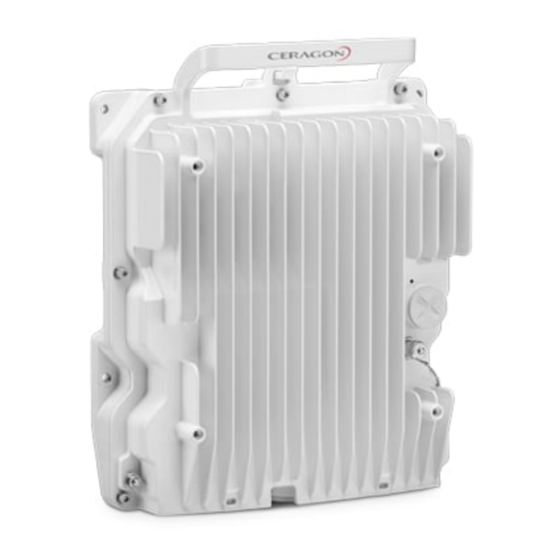
Ceragon FibeAir IP-20C-HP Manuals
Manuals and User Guides for Ceragon FibeAir IP-20C-HP. We have 3 Ceragon FibeAir IP-20C-HP manuals available for free PDF download: User Manual, Installation Manual
Ceragon FibeAir IP-20C-HP User Manual (825 pages)
All-Outdoor Products
Brand: Ceragon
|
Category: Multi-service Platforms
|
Size: 11.64 MB
Table of Contents
-
Introduction
44-
Web EMS51
-
-
PC Setup66
-
Logging on67
-
-
LAG Overview145
-
Configuring XPIC157
-
XPIC Overview157
-
AFR Overview184
-
Unit Management
191-
Configuring SNMP195
-
Configuring NTP220
-
-
-
RMON Statistics288
Advertisement
Ceragon FibeAir IP-20C-HP User Manual (945 pages)
Brand: Ceragon
|
Category: Network Hardware
|
Size: 13.13 MB
Table of Contents
-
-
-
Web EMS54
-
-
PC Setup69
-
Logging on70
-
-
LAG Overview166
-
Configuring XPIC180
-
XPIC Overview180
-
ASD Overview207
-
AFR Overview215
-
-
Configuring SNMP227
-
Configuring NTP254
-
-
-
RMON Statistics333
-
-
Qos Overview343
-
Marking Overview365
-
Enabling Marking366
-
Configuring WRED369
-
WRED Overview369
-
-
-
Configuring LLDP404
-
LLDP Overview404
-
-
-
RADIUS Overview442
-
-
-
General (CLI)518
-
PC Setup (CLI)519
-
Logging on (CLI)519
-
-
-
-
-
-
-
-
-
-
-
23 Maintenance
850-
RSL Interface854
-
Source Sharing854
-
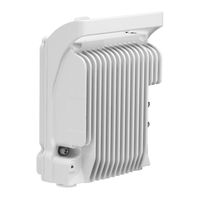
IP-20C Leds855
-
Radio LED856
-
Status LED856
-
Protection LED856
-
RSL Interface858
-
Source Sharing858
-
IP-20C-HP Leds859
-
Radio LED860
-
Status LED860
-
Protection LED860
-
RSL Interface864
-
IP-20S Leds864
-
Radio LED865
-
Status LED865
-
Protection LED866
-
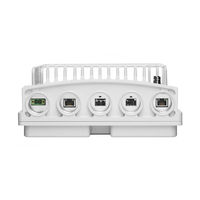
EXT Port871
-
23.13.1 Poe Port881

Ceragon FibeAir IP-20C-HP Installation Manual (204 pages)
Brand: Ceragon
|
Category: Wireless Access Point
|
Size: 4.23 MB
Table of Contents
-
-
Packing12
-
Unpacking12
-
Inspection12
-
Advertisement