Sign In
Upload
Manuals
Brands
Carrier Manuals
Refrigerator
NDK33BN6KB
Carrier NDK33BN6KB Manuals
Manuals and User Guides for Carrier NDK33BN6KB. We have
1
Carrier NDK33BN6KB manual available for free PDF download: Operation & Service Manual
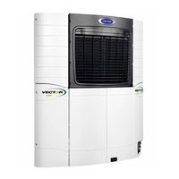
Carrier NDK33BN6KB Operation & Service Manual (270 pages)
Trailer Refrigeration Units
Brand:
Carrier
| Category:
Refrigerator
| Size: 10.17 MB
Table of Contents
Table of Contents
5
List of Illustrations
12
Hystory
15
Section 1 - Safety Precautions
16
General Product Safety Instructions on All Carrier Transicold Product
16
Important to Read and Follow During Regular Maintenance
16
Safety Precautions
17
Specific Warning and Caution Statements
17
Specific R-452A Refrigerant Warning and Caution
20
Safety Decals
22
Section 2 - Unit Description
25
Introduction
25
Refrigerant Types Used
25
General Description
25
Table 2-1. Model Chart
26
Condensing Section
33
Engine
33
Engine Air System
33
Engine Switches, Transducers and Sensors
33
Generator (GEN)
33
Compressor
33
Compressor Switches, Transducers and Sensors
33
Unloader Solenoid Valve (USV)
33
Liquid Injection Solenoid Valve (LIV)
33
Condenser Coil
33
Ambient Air Temperature Sensor (AAT)
34
Filter Drier
34
Receiver
34
Economizer Circuit
34
Evaporator Section
34
Evaporator Coil
34
Evaporator Expansion Valve (EVXV)
34
Compressor Suction Modulation Valve (CSMV)
34
Evaporator Switches, Transducers and Sensors
34
System Operating Controls and Components
35
Multiple Languages
35
Automatic Start-Stop
35
Special Features
35
Temperature Controller Component Description and Location
35
Electronic Modules
39
Overload Ground Fault Module (OGF)
39
Phase Reversal Module (PRM)
39
Options
39
Light Bar
39
Door/Remote Switch(Es)
39
Out of Range Alarm/Shutdown
39
Remote Temperature Sensors
40
Intelliset/Productshield
40
Remote Control Panel
40
Engine Data
40
Compressor Data
41
Refrigeration System Data
41
Electrical Data
42
Component Resistance & Current Draw Data
43
Safety Devices
43
Refrigerant Circuit During Cooling
43
Heat and Defrost
44
Section 3 - Operation
49
Starting Unit - Engine Operation
49
Starting Unit - Standby Operation
50
Self Test
51
Pretrip
52
Changing Set Point
55
Start-Stop Operation
56
Start-Stop Parameters
56
Restart Voltage
57
Charging Amps
57
Continuous Operation
58
Sleep Mode
59
Manual Defrost
61
Trip Start
62
View Active Alarms
63
View Inactive Alarms
64
Unit Data
65
Table 3-1. Unit Data
66
View Hourmeters
68
Functional Parameters
69
Table 3-2. Functional Parameters
70
Language Selection
73
Stopping Unit
74
Data Recording
75
Microprocessor Information
75
Data Downloading
75
Data Recorder Power-Up
75
Options
76
Intelliset
76
Remote Control Panel
79
Section 4 - Temperature Control
83
Introduction
83
System Start-Up
83
Standby Start-Up
83
Engine Start-Up
83
Transition to High Speed
84
Figure 4-1. Auto Start Sequence
84
Table 4-1. Glow Time
84
Start-Stop Operation
85
Start-Stop Configuration
85
Stop Parameters
85
Re-Start Parameters
86
Continuous Operation
86
Temperature Control
86
Temperature Determination
86
Heat/Cool/Null Mode Switching Logic
86
Cool Mode
87
Heat Mode
87
Null Mode
87
Defrost Mode
87
User Selected Override Operation
88
Supply Air Limit Control
88
Temperature Range Lock 1 & 2
89
Figure 4-2. Range Lock Settings - Non Overlapping
90
Figure 4-3. Range Lock Settings - Overlapping
90
Productshield
91
Productshield Temperature Ranges
92
Preprogrammed Software Overrides
92
High Discharge Temperature
92
RAT & SAT Alarms both Active
92
Engine Speed Overrides
92
Operating Mode Overrides
93
Section 5 - Technician Interface
95
Technician Configuration/ Test Modes (Remove Jumper Mode)
95
Configuration Mode
95
Component Test Mode
95
Figure 5-1. Technicians Interface Connections
95
Table 5-1. Component Test
96
Service Mode
97
Downloading Data with the Pc Card
98
INSTALLING NEW SOFTWARE USING a PC Card
99
Procedure
99
Troubleshooting Loading Problems
99
Logicold MICROPROCESSOR REPLACEMENT & CONFIGURATION SETUP
100
Microprocessor Replacement
100
Microprocessor Setup
100
Configurations Via Keypad
101
Functional Parameters Via Keypad
101
Microprocessor Final Checkout
102
Table 5-2. Microprocessor Configurations
102
Section 6 - Messagecenter
111
Messagecenter MESSAGES
111
Section 7 - Alarm Troubleshooting
117
Introduction
117
Notes
117
Driver / Operator Alarms
119
Low Fuel Level Warning
119
Shutdown Alarms
120
Low Engine Oil Pressure
120
High Coolant Temperature
121
High Discharge Pressure
123
High A/C Amps
124
Battery Voltage too High
125
Battery Voltage too Low
126
High Comp Discharge Temp
127
Low Refrigerant Pressure
128
Low Fuel Shutdown
130
Maximum Compressor Alarms
131
Technician Reset Required
131
Low Suction Superheat
132
A/C Current over Limit
133
Compression Ratio Exceeded
135
High Suction Pressure
136
Check Refrigeration System
148
Engine Stalled
148
Warning / Status Alarms
149
Alternator (Battery Charger) Not Charging
149
Box Temp Out-Of-Range
150
BOX TEMP OUT-OF-RANGE (Continued)
151
Defrost Not Complete
152
Check Defrost Air Switch
153
Check Remote Switch 1
154
Check Remote Switch 2
154
Datalogger (Datacorder) Not Recording
155
Datalogger (Data Recorder) Time Wrong
156
Door Open
157
Electrical Alarms
158
Bad F2 or F3 Fuse
158
Power-Check Power Cord
159
Comp Motor Overload
160
Condenser Motor Overheated
161
CONDENSER MOTOR OVERHEATED (Continued)
162
Evap (Evaporator) Motor Overheated
163
EVAP MOTOR OVERHEATED (Continued)
164
Check Remote Auto Light
165
Check Htcon1 Relay Coil
165
Check Htcon2 Relay Coil
166
Check Start up Buzzer
167
Check Comp Contactor 1 (Compressor Contactor Relay)
167
Check Cdcon Relay Coil
168
Check Genconr Relay Coil
168
Check High Temp Thermostat (Evhts)
169
Check Standby (Power Supply Contactor Relay) Coil
169
Overload/Ground Fault
170
Check Evcon Coil
171
CHECK BYPASS (Unloader) CIRCUIT
172
Check Economizer Circuit
173
Check Liv Circuit
174
Sensor Alarms
175
Check Ambient Air Sensor (Aat)
175
Check Return Air Sensor (Rat)
176
Check Supply Air Sensor (Sat)
177
Check Defrost Termination 1 Sensor (Dtt)
178
Check Compressor Discharge Sensor (Cdt)
179
Check Fuel Sensor (Fls)
180
Check Suction Temperature Sensor (Cst)
181
Amps Measure
182
Check Eng Coolant Sensor (Enct)
183
Check Engine Rpm Sensor (Enrpm)
184
Table 8-1. Maintenance Schedule
214
Figure 8-1. Fuel System Diagram
216
Figure 8-2. Fuel Bleed Components
216
Figure 8-3. Mechanical Fuel Pump
217
Figure 8-4. Electric Fuel Pump (Optional)
217
Figure 8-5. Fuel Level Sensor Wiring
217
Figure 8-6. Lube Oil Flow Diagram
218
Figure 8-7. Engine Speed Adjustment
218
Figure 8-8. Engine Crankcase Breather
220
Figure 8-9. Refrigerant System Service Connections
220
Table 8-2. CSMV Connections
233
Table 8-3. EVXV Connections
234
Table 8-4. Blower Wheel Identification
239
Table 8-5. Sensor Resistance (AAT, RAT, SAT, ENCT, EVOT, CST, DTT)
246
Table 8-6. Sensor Resistance (CDT)
247
Table 9-1. R-404A Temperature Pressure Chart
249
Advertisement
Advertisement
Related Products
Carrier NDK33BN0KB
Carrier NDK37BN6KB
Carrier Novello
Carrier Non-Programmable Thermostats
Carrier NSA-ASENSE-R-LCD-REL
Carrier N4H7T
Carrier N96MSN
Carrier NXX-4-W-AU
Carrier N2-USB-RS485 N2-AK-03
Carrier NXX-4-W-BO-AU
Carrier Categories
Air Conditioner
Heat Pump
Furnace
Thermostat
Chiller
More Carrier Manuals
Login
Sign In
OR
Sign in with Facebook
Sign in with Google
Upload manual
Upload from disk
Upload from URL