Sign In
Upload
Manuals
Brands
Carrier Manuals
Chiller
HFC-134a
Carrier HFC-134a Manuals
Manuals and User Guides for Carrier HFC-134a. We have
3
Carrier HFC-134a manuals available for free PDF download: Installation Instructions Manual, Start-Up, Operation And Maintenance Instructions Manual
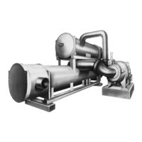
Carrier HFC-134a Start-Up, Operation And Maintenance Instructions Manual (32 pages)
Open-Drive Centrifugal Liquid Chillers 50/60 Hz
Brand:
Carrier
| Category:
Chiller
| Size: 4.06 MB
Table of Contents
Safety Considerations
1
Table of Contents
2
General
3
Introduction
3
Factory Test
3
Job Data
3
Field-Supplied Tools
3
Inspect Machine Room
3
Drive Arrangement
3
Piping
3
Wiring
3
Auxiliary Equipment Wiring
3
Motor Drive
4
Gas Engine Drive
4
Turbine Drive
4
Pumpout System
4
Leak Test and Dehydration
4
Charge Machine with Water
5
Charge Machine with Oil
5
Final Pre-Operation Alignment Check
5
Operate Drive
6
Set Purge Valves
6
Check Water Supply
6
Check Air Supply (Pneumatic Machines)
6
Start-Up
6
Pre-Operation Settings
6
Drive Operation
6
Initial Refrigerant Charge
6
Initial Compressor Operation
6
Adjust Refrigerant Charge
6
Hot Alignment Check and Doweling
7
Operational Testing
7
Instruct Customer Operator
7
Control Panel
7
Vfd
7
Steam Turbine
8
Gas Engine
8
Operating Procedures
8
Log Sheets
8
Operator Duties
8
Start Machine
8
Operation
10
Manual Operation
10
Cold Weather Operation
10
Stop Machine
10
Extended Shutdown
10
Pumpout System Operation
11
Lubrication
11
Control Description
11
Control Setting
11
Machine and Storage Tank Evacuation
11
Remove Air after Opening Chiller to
12
TRANSFER REFRIGERANT CHARGE (from Storage Tank to Machine)
12
Transfer Refrigerant Charge
12
Machine to Storage Tank Located below Machine
12
Machine to Storage Tank Located above or Level with
12
Pressurize Machine and Storage Tank
12
Distill Refrigerant Charge
12
Charge Refrigerant
13
Maintenance
13
Weekly Maintenance
13
Check Oil Level
13
Check Purge Frequency
13
Water in Purge Water Chamber
13
Operation
13
Yearly Maintenance
13
Check/Calibrate Water Temperature Sensors
13
Check Refrigerant Low-Pressure Cutout
13
Check Seal Oil Differential Pressure
14
Transducer
14
Check Thrust Bearing Oil Pressure
14
Check Discharge Gas High-Temperature
14
Check Thrust Bearing Oil High-Tempera
14
Ture Cutout
14
Check Shaft Movement Switch
14
Check Cooler and Condenser Minimum
14
Flow Protection
14
Check Auxiliary Interlocks
14
Check Starters and Vfds
15
Change Oil and Oil Filter
15
Inspect Cooler Tubes
15
Inspect Condenser Tubes
15
Inspect Purge Recovery Unit
15
General Maintenance
15
Refrigerant Level
15
Leak Testing
15
Check Leakage Rate
15
Breaking Vacuum
16
Refrigerant
16
Preparing Machine for Charging
16
Chiller Dehydration
16
Removing Refrigerant
17
Water Treatment
17
Gear and Drive
17
Pumpout System
17
Maintenance
17
General Data
17
Machine Nameplate
17
Refrigerant Properties
17
Relief Valve Assembly
17
System Components
17
Refrigeration Cycle
18
Oil Cycle
18
Purge Cycle
19
Troubleshooting
20
Compressor will Not Start
20
Compressor Surge
20
Chilled Water Temperature too High
20
Chilled Water Temperature too Low with Compressor Running
22
Refrigerant Temperature too Low
22
Leaving Chilled Water Temperature Fluctuates
22
Condenser Pressure too High
22
Oil Pressure too Low
22
Oil Pressure too High
22
Oil Reservoir Temperature too Low
22
Oil Reservoir Temperature too High
22
Compressor Discharge Gas Temperature
22
Too High
22
Operating Controls
23
Controls
27
Pre-Start up Check List
32
Advertisement
Carrier HFC-134a Installation Instructions Manual (67 pages)
50/60 Hz Hermetic Centrifugal Liquid Chillers HFC-134a
Brand:
Carrier
| Category:
Chiller
| Size: 1.12 MB
Table of Contents
Safety Considerations
1
Table of Contents
7
Safety Considerations
12
Introduction
12
General
12
Job Data
12
Equipment Required
13
Installation
14
Receiving the Machine
14
Inspect Shipment
14
Identify Machine
15
Provide Machine Protection
15
Rigging the Machine
16
Rig Machine Assembly
16
Install Machine Supports
17
Connect Piping
19
Install Water Piping to Heat Exchangers
19
Install Water Piping to Oil Cooler
21
Attach Water Supply to Pumpout Condenser
23
Install Vent Piping to Relief Devices
23
Make Electrical Connections
25
Connect Control Inputs
26
Connect Control Outputs
26
Connect Free-Standing Field Installed Starter
26
Carrier Comfort Network Interface
31
Install Field Insulation
34
Figure 1 - Model Number Identification
40
List of Figures
40
Figure 11 - Piping Flow Data (Condenser, NIH Waterboxes)
51
Figure 12 - Water Piping, Oil Cooler to Chilled Water Circuit (Typical)
51
Figure 13 - Pumpout Unit
52
Figure 14 - Typical 19FA Relief Valve Tree for Storage Vessel
53
Figure 15 - Compressor Terminal Arrangement 18-Lead, Rear Inlet
54
Figure 2 - Typical 19FA Installation (1400-2200 Tons [4922-7735 Kw])
41
Figure 3 - Machine Rigging Guide
42
Figure 4 - 19FA Dimensions
43
Figure 5 - Machine Footprint
44
Figure 6 - Machine Contact Surfaces with Anchor Bolts
45
Figure 7 - Typical Nozzle Piping
46
Figure 8 - Piping Flow Data (Cooler, Marine Waterboxes)
47
Figure 9 - Piping Flow Data (Cooler, NIH Waterboxes)
48
Figure 10 - Piping Flow Data (Condenser, Marine Waterboxes)
49
Installation Start-Up Request Checklist
66
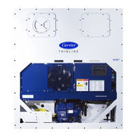
Carrier HFC-134a Installation Instructions Manual (52 pages)
High-Efficiency Variable Speed Screw Chiller with Foxfire Compression Technology and PIC III Controls 50/60 Hz HFC-134a
Brand:
Carrier
| Category:
Chiller
| Size: 12.59 MB
Table of Contents
Safety Considerations
1
Installation Instructions
1
General
2
Table of Contents
2
Introduction
2
General
2
Job Data
2
Installation
2
Receiving the Machine
2
Inspect Shipment
2
Identify Machine
2
Installation Requirements
2
Provide Machine Protection
2
Rigging the Machine
3
Rig Machine Assembly
3
Rig Machine Components
11
Separate Machine Components
13
Separate Cooler and Condenser
13
Remove the Controls/Drive Enclosure
14
From the Condenser
14
Condenser
15
Remove the Discharge Pipe Assembly from the Condenser
16
Separate the Compressor from the Condenser
17
Condenser
18
Separate the Vaporizer from the
19
VFD Installation
19
Install Machine Supports
22
Install Standard Isolation
22
Install Accessory Isolation
23
Install Spring Isolation
24
Connect Piping
24
Install Water Piping to Heat Exchangers
24
Top View
27
Front View
27
Install Vent Piping to Relief Valves
30
Make Electrical Connections
30
Grounding the Controls/Drive Enclosure
31
Installing Input Power Wiring
31
Wiring the Field Wiring Terminal Strips
37
Enclosure
37
Connect Control Inputs
37
Connect Control Outputs
37
Connect Starter
37
Completing the Installation
43
Checking the Installation
43
Oil Pump and Oil Heater
43
Connect Control Wiring
43
Carrier Comfort Network Interface
43
Lead-Lag Control Wiring
44
Install Field Insulation and Lagging
44
Installation Start-Up Request
51
Checklist
51
Advertisement
Advertisement
Related Products
Carrier HS070-160
Carrier HXC076-186
Carrier HJ
Carrier EVERGREEN HXC076-271
Carrier ComfortLink HXC076
Carrier ComfortLink HXC271
Carrier HUMCCWTR2019-A Series
Carrier HRVXXLVU1330
Carrier HP01-B
Carrier HT01CN241
Carrier Categories
Air Conditioner
Heat Pump
Furnace
Thermostat
Chiller
More Carrier Manuals
Login
Sign In
OR
Sign in with Facebook
Sign in with Google
Upload manual
Upload from disk
Upload from URL