Sign In
Upload
Manuals
Brands
Cagiva Manuals
Motorcycle
Navigator
User Manuals: Cagiva Navigator Motorcycle engine
Manuals and User Guides for Cagiva Navigator Motorcycle engine. We have
1
Cagiva Navigator Motorcycle engine manual available for free PDF download: Workshop Manual
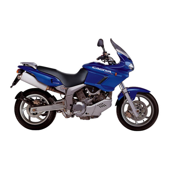
Cagiva Navigator Workshop Manual (408 pages)
Brand:
Cagiva
| Category:
Motorcycle
| Size: 23.4 MB
Table of Contents
Workshop Manual
1
General Repairing Rules
2
Identification Data
3
Table of Contents
4
General Information
5
Dimensions and Weights
7
General Information
7
Maintenance
10
Maintenance
11
Fuel Tank Removal
12
Maintenance and Tuning
12
Air Filter
14
Spark Plugs
15
Carbon Deposits
17
Heat Grade Code
17
The Condition of the Electrodes
17
The Gap between the Spark Plug Electrodes
17
Front Cylinder
18
Valve Tappet Clearance Adjustment
18
Rear Cylinder
19
Intake Valve Pads Selection Table
22
Exhaust Valve Pads Selection Table
23
Engine Oil and Oil Filter
24
Engine Oil Change
24
Fuel Tubing
24
Torque Pressure
24
Minimum Tickover
25
Oil Capacity
25
Oil Filter Substitution
25
Accelerator Cable Play
26
Synchronisation of the Carburettors
26
Clutch
27
Cooling System
27
Engine Coolant Change
28
Radiator Tubes
29
Transmission Chain
29
Chain Adjustment
30
Cleaning and Lubrication
30
Brake Fluid Level Check
31
Brake Pads
31
Brakes
31
Brake Pedal Height
32
Bleeding the Air from the Braking System
33
Condition of the Tread
34
Steering
34
Tyre Pressures
34
Tyres
34
Compression Specification
35
Compression Test
35
Compression Test Procedure
35
Low Oil Pressure
36
Oil Pressure Specification
36
Oil Pressure Test
36
Oil Pressure Test Procedure
36
Specifications
37
Technical Data
37
Tyre Pressures
43
Injection - Air Intake System
46
Maintenance Precautions
47
Connectors/Couplings
47
Injection - Air Intake System
47
Ecm/Various Sensors
48
Fuses
48
Electrical Circuit Testing Procedure
49
Open Circuit Tests
49
Continuity Test
50
Short Circuit Tests
51
Voltage Test
51
Use of the Tester
52
Fi System Technical Characteristics
53
Injection Time (Injection Volume)
53
Injection Kill Control
54
Injection Time Adjustment (Volume)
54
Electric Fuel Pump
55
Fuel Feed System
55
Fuel Injector
56
Fuel Pressure Regulator
56
Fuel Pump Control System
57
Ecm (Fi Control Unit)
58
Injection Synchronisation
59
Intake Air Suction Sensor (Iap Sensor)
60
Sensors
60
Throttle Position Sensor (Tp Sensor)
60
Camshaft Position Sensor (Cmp Sensor)
61
Crankshaft Position Sensor (Ckp Sensor)
61
Engine Coolant Temperature Sensor (Ect Sensor)
62
Intake Air Temperature Sensor (Iat Sensor)
62
Atmospheric Pressure Sensor (Ap Sensor)
63
Crash Sensor (to Sensor)
63
Intake Air System Technical Characteristics
64
Position of the Fi System Components
65
Fi System Diagram
66
Fi Electrical System Diagram
67
Auto-Diagnostic Function
68
User Mode
68
Dealer Mode
69
Security Function
71
Client’s Claim Analyses
72
Fi Diagnostic System
72
Auto-Diagnostic Procedure
73
Auto-Diagnostic Starting Procedure
73
Malfunction Codes and Malfunctions
74
C11 Cmp Sensor Circuit Malfunction
76
“C12” Ckp Sensor Circuit Malfunction
77
“C13” Sensor Circuit Malfunction
78
Tp “C14” Sensor Circuit Malfunction
80
Ect “C15” Sensor Circuit Malfunction
82
“C21” Iat Sensor Circuit Malfunction
83
“C22” Ap Sensor Circuit Malfunction
84
“C23” to Sensor Circuit Malfunction
86
“C24” or “C25” Ignition System Malfunction
87
“C31” Gearchange Sensor Circuit Malfunction
87
“C32” or “C33” Fuel Injection Malfunction
88
“C41” Fp Relay Circuit Malfunction
89
Fuel Pressure Check
90
Fuel Flow Quantity Control
91
Fuel Pump Control
91
Fuel Pump Relay Check
91
Fuel Pump Removal
91
Fuel Reserve Probe
92
Incoming Fuel Filter
92
Intake Filter
92
Air Filter Removal
93
Butterfly Body
94
Butterfly Body Removal
95
Check
101
Cleaning the Carburettor
101
Carburettor Reassembly
102
Air Screw Adjustment
109
Fuel Injector Assembly
109
Fuel Injector Check
109
Fuel Injector Removal
109
Choke Adjustment
110
Calibration Accessory
111
Carburettor Synchronisation
111
Butterfly Valve Synchronisation
112
Throttle Lever Play
114
Throttle Position Sensor Adjustment (Tps)
114
Choke Cable Adjustment
115
Major Adjustments
115
Throttle Cable Adjustment
115
Ckp Sensor Check
116
Iap Sensor Check
116
Iap Sensor Removal/Reassembly
116
Tp Sensor Check
116
Ap Sensor Removal/Reassembly
117
Ect Sensor Check
117
Iat Sensor Check
117
Iat Sensor Removal/Reassembly
117
Engine
120
Engine Central Part
121
Engine Components that Can be Removed Without Removing the Engine
121
Engine Left Side
121
Engine Right Side
121
Removing the Engine
122
Exhaust Silencer Removal
124
Installation of the Engine into the Frame
131
Disassembling the Engine
138
No. 1 (Front) Cylinder
139
No. 2 (Rear) Cylinder
142
Assembling the Engine
158
Driven Plates
172
Driving Plates
172
Front No. 2 Valve Motion Idler Gear/Sprocket
184
No. 1 (Front) Timing Chain Tension Adjuster
186
Rear No. 2 Valve Motion Idler Gear/Sprocket
188
No. 2 (Rear) Timing Chain Tension Adjuster
189
No. 2 (Rear) Camshafts
193
Camshaft/Cylinder Head
199
Description of the Valve Gear System
201
Front Camshafts
203
Precautions for Installation
203
Rear Camshafts
203
Valve Timing Diagram
204
Valve Timing Chart
205
No. 1 (Front) Camshafts
206
Removing the Camshafts
206
Cam Wear
208
Checking and Servicing the Camshafts and the Cylinder Head
208
Camshaft Journal Wear
209
Camshaft Gears and Automatic Decompressor
210
Camshaft Runout
210
Timing Chain Guide and Chain Stretcher
210
Timing Chain Tension Adjuster
210
Cylinder Head
211
Cylinder Head Distortion
212
Valve Head Radial Runout
212
Valve Seal Surface Wear
212
Valve Stem Runout
212
Valve Guide Servicing
213
Valve Stem Deflection
213
Valve Stem Wear
213
Valve Seat Servicing
214
Valve Seat Width
214
Valve Spring
216
No. 2 Valve Motion Idler Gear/Sprocket Thrust Clearance
217
Cylinder Head Assembly
218
Camshaft Position Sensor
219
Exhaust Pipe
219
Intake Pipe
219
Installing the Camshafts
220
No. 1 (Front) Camshaft
220
No. 2 (Rear) Camshaft
221
Cylinder/Piston
223
Cremoving the Cylinder and the Piston
224
No. 1 (Front) Cylinder and Piston
224
No. 2 (Rear) Cylinder and Piston
225
Checking the Cylinder and the Piston
226
Cylinder Barrel
226
Cylinder Block Distortion
226
Piston Diameter
226
Piston Ring/Piston Groove Clearance
227
Piston/Cylinder Clearance
227
Piston Pin and Piston Pin Bore
228
Piston Ring Free End Gap and Piston Ring End Gap
228
Installing the Piston and the Cylinder
229
No. 1 (Front) Piston and Cylinder
230
No. 2 (Rear) Piston and Cylinder
231
Removing the Clutch
233
Removing the Clutch Throw-Out
234
Checking the Clutch and the Throw-Out
235
Clutch Driving Plates
235
Clutch Bearing
236
Clutch Driven Plates
236
Clutch Spring Free Length
236
Clutch Throw-Out
236
Installing the Clutch
237
Installing the Clutch Throw-Out
240
Water Pump/Clutch Cover
241
Removing the Water Pump and the Clutch Cover
242
Checking the Mechanical Seal and the Sealing Washer
243
Checking the Oil Seal
243
Removing the Oil Seal and the Mechanical Seal
243
Installing the Oil Seal and the Mechanical Seal
244
Installing the Water Pump and the Clutch Cover
245
Primary Driving Gear/No. 1 Valve Motion Idler Gear/Sprocket Shaft
247
Removing the Primary Driving Gear and the No. 1 Valve Motion Idler Gear/Sprocket Shaft
248
Assembling the Primary Driving Gear
250
Checking and Servicing the Primary Driving Gear
250
Disassembling the Primary Driving Gear
250
Fitting the Primary Driving Gear and the No. 1 Valve Motion Idler Gear/Sprocket Shaft
251
Starting System/Generator/Crankshaft Position Sensor
252
Removing the Starting Torque Limiter, the Generator and the Crankshaft Position Sensor
253
Checking and Servicing the Starting Torque Limiter, the Generator and the Crankshaft Position Sensor
255
Checking the Starter Motor Shaft Bearing
255
Checking the Starter Coupling
256
Servicing the Generator Stator and the Crankshaft Position Sensor
256
Servicing the Starter Coupling
256
Installing the Starting Torque Limiter, the Generator and the Crankshaft Position Sensor
258
Checking and Servicing the Starter Motor
260
Installing the Starter Motor
260
Removing the Starter Motor
260
Gear Preselector
261
Removing the Gear Preselector Assembly
262
Checking and Servicing the Gear Preselector Assembly
264
Fitting the Gear Shaft/Arm
264
Removing the Gear Shaft/Arm
264
Checking the Gear Shaft Hole
265
Replacing the Oil Seal
265
Installing the Gear Preselector Assembly
266
Crankcase/Gearbox/Crankshaft/Connecting Rod
269
Checking and Servicing the Transmission
271
Fork-Groove Play
271
Removing the Transmission, the Crankshaft and the Connecting Rod
271
Driving Shaft
273
Checking and Servicing the Connecting Rod Bearings/Crankpins
278
Checking the Connecting Rod and the Crankshaft
278
Selecting the Connecting Rod-Crankpin Bearings
279
Bearing Thickness
280
Connecting Rod I.D. Specification
280
Connecting Rod O.D. Specification
280
Checking and Servicing the Crankshaft Bearings
281
Bearing Selection Table
282
Replacing the Crankshaft Bearings
282
Selecting the Crankshaft Bearings
282
Adjusting the Crankshaft Thrust Clearance
285
Installing the Transmission, the Crankshaft and the Connecting Rod
286
Engine Lubrication System
287
Oil Pump
288
Oil Sump Filter/Oil Pressure Regulator
290
Checking the Oil Pressure Regulator
291
Cleaning the Oil Sump Filter
291
Installing the Oil Sump Filter
292
Oil Pressure Switch/Oil Cooler
293
Checking and Cleaning the Oil Cooler
294
Checking the Oil Cooler Pipes
294
Oil Filter
295
Oil Pressure
295
Piston Cooling Oil Jet/Oil Nozzle
295
Engine Lubrication Chart
296
Oil Sump
296
Engine Lubrication System
297
Suspensions and Wheels
300
Front Wheel
301
Front Wheel Removal
301
Suspensions and Wheels
301
Front Wheel Bearing Substitution
302
Front Wheel Overhaul
302
Bent Wheel Spindle
303
Wheel Assembly
303
Front Fork Removal
304
Front Suspension
304
Fork Assembly Overhaul
305
Support Tube Sliding Assembly Removal
306
Support Tube Sliding Assembly – Reassembly
307
Fork Assembly – Reassembly
310
Steering Reassembly
314
Rear Wheel
315
Rear Wheel Removal
315
Chain, Crown Wheel and Pinion Wheel Overhaul
316
Crown Wheel Substitution
316
Rear Wheel Overhaul
316
Pinion Wheel Substitution
317
Substitution of the Chain
317
General Check of the Shock Absorber
318
Rear Shock Absorber Removal
318
Rear Suspension
318
Pre-Load Spring Adjustment
319
Removal/Check of the Rear Wheel Compensator Assembly
319
Shock Absorber Hydraulic Brake Setting
319
Rear Fork Removal
321
Frame
323
Reassembly - Compensator Assembly
321
Frame Substitution
323
Brakes
326
Brake Pad Wear Check
327
Disc Brake
327
Front Brake
328
Rear Brake
328
Brake Fluid Substitution
329
Front Brake Pincer Assembly Removal
331
Rear Brake Pincer Removal
332
Front Brake Pump Assembly Removal
333
Brake Pump Reassembly
334
Rear Brake Pump Removal
335
Electrical Equipment
338
Electrical Equipment
340
Colour Legends
341
Electrical Wiring System Diagram
341
Connecting Terminals
342
Connectors
342
Precautionary Maintenance Advice Connectors
342
Semiconductor Parts
342
Charging the Battery
343
Charging System
344
Function of the Rectifier
344
Diagnostics
346
The Battery Discharges Rapidly
346
Battery Current Leakage Test
347
Charge Output Test
347
Generator Winding Resistance Test
348
Rectifier Test
348
Testing the Generator Performance in the Absence of a Charge
348
Starter System and Side Stand/Ignition Security System
349
Starter System Description
349
Side Stand/Ignition Security System Description
350
The Starter Motor Does Not Turn
351
Brushes
352
Starter Motor Check
352
Starter Motor Removal and Disassembly
352
Commutator
353
Oil Seal Check
353
Rotor Winding Check
353
Starter Motor Reassembly
353
Starter Relay Check
354
Diode
355
Testing the Parts of the Side Stand/Ignition Security System
355
Gearchange Position Switch
356
Side Stand Switch
356
Injection Relay and Fuel Pump Relay
357
Crankshaft Position Sensor
358
Engine Coolant Temperature Sensor
358
Ignition System
358
Throttle Position Sensor
358
Worn or Non-Firing Spark Plugs
360
Peak Voltage of the Primary Winding of the Ignition Coil
361
Test
361
Ignition Coil Resistance
362
Circuit Tester Dial Indication
363
Crankshaft Position Sensor Resistance
364
Instruments
365
Engine Coolant Temperature Sensor and Indicator Check
367
Fourth Phase
367
Second Phase
367
Third Phase
367
Oil Pressure Warning Light Test
369
Speedometer Check
369
Speedometer Sensor Check
369
Halogen Lamp Substitution
370
Headlight
370
Lights
370
Front Direction Indicator Bulb Substitution
371
Instrument Panel Bulb Substitution
371
Rear Light and Rear Direction Indicator Bulb Substitution
371
Headlight Beam Adjustment
372
Direction Indicator Relay
373
Fuel Pump Relay
373
Starter Relay
373
Ignition Switch
374
Light Commutator
374
Light Switch
374
Switches
374
Engine Cooling
377
Cooling System
378
Engine Cooling
378
Construction
379
Engine Coolant
380
Engine Coolant - Radiator and Tubes
381
Radiator Cap Check
382
Cooling System Tubes Check
383
Radiator Check and Cleaning
383
Radiator Mounting Bolt
383
Cooling Fan
384
Fan Mounting Bolts
384
Radiator Mounting Bolts
384
Cooling Fan Thermal Switch
385
Engine Coolant Temperature Sensor
387
Temperature Sensor Specification
387
Thermostat
388
Water Pump
389
Specific Tooling
391
Specific Tooling
392
Torque Pressures
395
Exhaust System
399
Index
401
Index
402
Advertisement
Advertisement
Related Products
Cagiva 1994 MITO ev
Cagiva 1997 Canyon 500
Cagiva 1999 MITO ev
Cagiva 2003 Planet 125
Cagiva 2005 Canyon
Cagiva 2007 raptor 125-E 3
Cagiva 900 ie
Cagiva Elefant 650 USA
Cagiva mito 525 E3
Cagiva Categories
Motorcycle
Scooter
More Cagiva Manuals
Login
Sign In
OR
Sign in with Facebook
Sign in with Google
Upload manual
Upload from disk
Upload from URL