Sign In
Upload
Manuals
Brands
Bukh Manuals
Engine
DV20
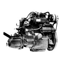
User Manuals: Bukh DV20 Marine Diesel Engine
Manuals and User Guides for Bukh DV20 Marine Diesel Engine. We have
2
Bukh DV20 Marine Diesel Engine manuals available for free PDF download: Workshop Manual
Bukh DV20 Workshop Manual (325 pages)
Diesel
Brand:
Bukh
| Category:
Engine
| Size: 13.14 MB
Table of Contents
Contents
4
List of Tools for DV Engines
5
Installation Tools
7
Service Tools
7
Installation Dummy for DV10 and DV20 with BW6 Gear
8
Installation Dummy for DV10 and DV20 with BW7 Gear
9
Repair Tools
10
General Description and Technical Data
17
Cylinder Head
19
Crankcase
19
Crankshaft
20
Flywheel
20
Connecting Rod
20
Piston and Cylinder Liner
21
Camshaft
21
Lubricating Oil System
21
Cooling Water System
22
Fuel System
22
Two-Stage Combustion
22
Vibration Damping
22
Sectional Drawing of DV20SME
23
Technical Data for DV10
24
Torque, Rating, Consumption Curve for DV10
25
Technical Data for DV20
26
Torque, Rating, Consumption Curve for DV20
27
Torque in KGM (Ft.lbf)
28
Cylinder Head DV10
31
Cylinder Head DV20
32
Change of Rocker Arm or Rocker Shaft
33
Exchange of Bushing in Rocker Arm
34
Dismounting of Cylinder Head
35
Mounting of Cylinder Head
35
Valve Adjustments
36
Dismounting of Fuel Valves
37
Mounting of Fuel Valves
37
Inlet Valve - Machining Dimensions and Tolerances
38
Exhaust Valve - Mounting and Tolerances
39
Minimum Repair Measures for Inlet Valve and Exhaust Valve
40
Repair or Change of Exhaust and Inlet Valves
41
Grinding Takes Place as Follows
42
Change of Valve Guides
43
Pressing-In Measures for Valve Guides - DV 10 and DV 20
44
Changing of Valve Seats
45
Mounting of Valve Seat Rings
45
Measures for Bores for Valve Seats
45
Machining and Mounting Dimensions for Inlet and Exhaust Valve Seat
46
Cylinder Head Gasket
47
Mounting of Valve Springs
48
Adjustment of Decompression Lever
49
Vacuum Valve for DV 10 and DV 20
50
Surfacing of Cylinder Head
51
Packing Grooves
51
Precombustion Chamber
51
Compression Gauging
52
Operation Instruction
53
Dismounting of Flywheel
57
Mounting of Flywheel
57
Adjustment of V-Belt
58
Replacement of Gear Rim
59
Front End Cover
61
Dismounting of Counterweights
63
Mounting of Counterweights
64
New Marking
65
Tightening of Shafts for Counterweights
65
Arrangement of Counterweight
66
Replacement of Oil Seal Ring in Guard
67
Replacement of Front End Cover
68
Replacement of Axle Journals for Counterweights
68
Replacement of Front Main Bearing Lining
68
Raised Hand Start
69
Raised Hand Start on Front Edge
71
Checking of Chain for Raised Hand Start
71
Dismounting of Raised Hand Start on Front Edge
72
Dismounting of Raised Hand Start on Rear Edge
74
Rear End Cover
77
Dismounting of Rear End Cover
79
Removal of Rear Counterweights
80
Exchange of Bearings for Counterweights
80
Fitting of Counterweights
80
Tightening of Shafts for Rotating Weights
81
Arrangement of Rotating Weights
82
Tightening of Pipe Plugs in Rear End Cover
83
Governor System
84
Dismounting of Centrifugal Governor
85
Fitting of Centrifugal Governor
86
Dismounting of Manual Governor
87
Mounting of Manual Governor
88
Characteristic for Governor Spring
89
Adjustment of Governor System
90
Dismounting and Adjustment of Stop Button
91
The Fuel System
95
Bleeding of the Fuel System
96
Fuel Lift Pump
97
Dismounting and Mounting of the Fuel Lift Pump
97
Repair of Fuel Lift Pump Type AC-DELCO
98
Remedy of Leaks
98
Technical Data of the Fuel Lift Pump
100
Counter Pressure
100
Disassembly of Fuel Lift Pump
100
Cleaning of Suction Filter
100
Exchange Diaphragm as Follows
101
Fuel Lift Pump S.E.V. Marchal Type 70 BA
102
Fuel Filter
103
Fuel Filter Element: BOSCH No. 04500 15014
103
Exchange of Fuel Filter Element
103
Dismounting of the Fuel Pump
107
Dismantling of the Fuel Pump
107
Assembling of the Pump
109
Capacity of the Fuel Pump
110
Fuel Pump Type BRYCE
111
Disassembly of Fuel Pumps
111
Disassembly of the Roller Section
111
Disassembly of the Pressure Valve Section
112
Checking of the Control Sleeve
113
Reassembly of Fuel Pumps
113
Testing of BRYCE Fuel Pumps
113
Adjustment of Injection Timing (Spill Point)
117
Data for Injection Timing
117
Adjustment of Injection Timing
117
Fuel Valve
120
Dismounting and Dismantling of the Fuel Valve
121
Adjustment of Opening Pressure
123
Nozzle Tester
124
Operating Instructions for Bosch Nozzle Tester
125
Cleaning of Nozzles
125
Preliminary Testing
125
Testing with Nozzle Tester
126
Testing of Tightness
127
Snarl Test and Injection Angle
127
Maintenance
128
Piston, Connecting Rod, and Cylinder Liners
129
Dismounting of Pistons and Connecting Rods
131
Change of Pistons
132
Test Measurement of Piston DV10-DV20
133
Change of Piston Rings
134
Exchange of Piston Pin Bearing
135
Arrangement of Connecting Rod
136
Mounting of Pistons and Connecting Rods
137
Connecting Rod Bearings
137
Cylinder Liner
138
Measuring of Cylinder Wear
138
Dismounting of Cylinder Liner
138
Mounting of Cylinder Liner
138
Arrangement of Cylinder Linear
139
Test Equipment of Cylinder Liner
140
Fitting of Oil Dip Stick
143
Fitting of Oil Dip Stick for DV10 and DV20
144
Fitting of Inlet Connecting Piece
145
Tightening of Lubricating Oil Grooves
145
Crank Shaft, Intermediate Bearing and Rear Main Bearing Bush
147
Repair Dimensions of Crank Shaft
149
Front Main Bearing Journal
149
Rear Main Bearing Journal
149
Intermediate Bearing Journal
149
Connecting Rod Journals
150
Exchange of Crank
150
Dismounting of Crank Shaft
151
Change of Intermediate Bearing
152
Camshaft, Complete
153
Dismounting of the Camshaft
155
Change of Front Bearing Bush for Camshaft
156
Check of Camshaft
157
Valve Times
157
Injection Timer
158
Dismounting
158
Mounting
158
Check of Injection Timer
159
Arrangement of Automatic Injection Timer
160
Lubricating System
161
Excess-Pressure Valve
163
Lubricating Filter
163
Arrangement Drawing of Lubricating Oil Reduction Valve
164
Lubricating Pump - Old Type
165
Lubricating Oil Pump in Old Execution
166
Lubricating Oil Pump in New Execution
166
Lubricating Oil Pump - New Type
167
Lubricating Oil Quality
167
Direct Cooling (Seawater Cooling Water Pump)
171
Technical Data
172
Technical Data - Pump for DV20
172
Dismantling of Cooling Water Pump
173
Thermostat
174
Fitting of Double Transmitter
176
Zinc Rod
177
Indirect Cooling (Freshwater Cooling)
178
Heat Exchanger System
178
DV20 Engines
178
DV10 Engines
178
Cooling Water System for DV10 and DV20
179
Thermostat Housing
179
Header Tank
179
Keel Cooling
180
Common Components
180
Freshwater Circulating Pump
180
Dismantling of Circulating Pump
180
Expansion Cover
181
Type of Cover
181
Protection against Front
181
Arrangement of Circulating Pump
182
Arrangement of Heat Exchanger DV20
183
Arrangement of Keel Cooling DV10
184
Arrangement of Keel Cooling DV20
185
The Electrical System
187
Dynastarter
189
Supervisory Relay
190
Dimensions of Starter Cables and Technical Data for the Electrical System
191
Stop Magnet
194
Safety Regulations
195
Battery
195
Electrical System
197
Alternator
198
Maintenance Instructions for Motorola Alternator
203
Alternator Type a 14/30
204
Fault Localization
204
Checking and Testing of Alternator and Voltage Relay
205
Voltage Relay
206
Checking of Voltage Relay
206
Checking of Alternator
207
Examination of Insulating Diode Bridge
207
Exciting Circuit
207
Checking of Rectifier Diodes
209
Alternator Type 14/35 a
210
Fault Localization of Alternator
210
Voltage Relay - Type T14V
211
Checking of Rotor Windings
211
Checking of Magnetizing (Trio) Diodes
212
Check the Diode Connection
212
Checking of Trio Diodes
212
Removal of Diode Set
213
Reassembly of Alternator
213
Fitting of Voltage Regulator
214
Checking at Starting-Up
214
Change of Starter Motor into Two-Wire Execution
215
Change of Alternator into Two-Wire Execution
216
Wiring Diagram for Dynastarter with Instrument Panel
222
Wiring Diagram for Dynastarter with Operating Panel
223
Wiring Diagram for Dynastarter with Thermostat
224
Wiring Diagram for Dynastarter with Thermostat and Operating Panel
225
Wiring Diagram for Dynastarter
226
Wiring Diagram for Alternator
227
Diagram for Standard Electrical System
228
Diagram for Fully Developed Electrical System
229
Standard Operating Panel with Warning Lamps, Key Switch and Acoustic Alarm
233
Marine Reduction Gear ZF - BW6
235
ZF Gear - BW7
247
Gear Ratio
249
Oil Change
249
Special Tools
251
Adjusting Measures and Torques for BW7
252
General Information for Work with the Gear
254
Removal of Gear from Engine
254
Dismantling of BW7 Gear
255
Dismantling of Shifting Fork
258
Dismantling of Output Shaft
258
Dismantling of Input Shaft
260
Dismantling of Lower Gearbox Half
260
Dismantling of Upper Gearbox Half
260
Refitment of BW7 Gear
261
Measuring of Tightening of Tapered Roller Bearing on Input and Output Shafts with Measuring Gauge
267
Measuring of Tapered Roller Bearing Tightening on Input and Output Shafts Without Measuring Gauge
269
Pre-Mounting of Shifting Fork
270
Fitting of Bolts in Gearbox
272
Transmission
272
Fitting of Input and Output Shafts with Shifting Fork in Gearbox
273
Fitting of Shaft Seal Rings
276
Supplement to Fitting of Shaft Seal Rings
277
Sail Drive Type Z-7
281
Oil Change and Gear Ratio
283
Zinc Anode
283
Outside Maintenance
283
Removal of Sail Drive from Engine and Boat
283
Alarm Function of Double Membrane
285
Assembling Procedure for Sail Drive
287
Intermediate Housing and Intermediate Shaft
292
Irregularities in Operation
297
Causes and Remedies for the Engine and the Electrical System
297
The Engine Does Not Start or Is Difficult to Start
301
Engine Starts, but Stops Shortly after
303
Engine Does Not Reach Maximum Capacity
303
Knocking Operation of Engine
303
Engine Speed too High
303
Engine Knocks
305
Engine Had Black Exhaust Smoke
305
Engine Has Bluish Exhaust Smoke
305
Excessive Lubricating Oil Consumption
305
Engine Run Hot
307
Causes to Irregularities in the Electric Starter
309
Maintenance Schedule
319
Storage
321
Advertisement
Bukh DV20 Workshop Manual (306 pages)
Brand:
Bukh
| Category:
Engine
| Size: 63.58 MB
Table of Contents
Table of Contents
246
Gear Ratio
247
Oil Change
247
Special Tools
249
Adjusting Measures and Torques for BW7
250
General Information for Work with the Gear
252
Removal of Gear from Engine
252
Dismantling of BW7 Gear
253
Removal of Input and Output Shafts
255
Dismantling of Shifting Fork
256
Dismantling of Output Shaft
256
Dismantling of Input Shaft
258
Dismantling of Lower Gearbox Part
258
Dismantling of Upper Gearbox Part
258
Refitment of BW7 Gear
259
Fitting of Input Shaft
264
Measuring of Tightening and Tapered Roller Bearing on Input and Output Shafts with Measuring Gauge
265
Premounting of Shifting Fork
268
Fitting of Bolts in Gearbox
270
Fitting of Input and Output Shafts with Shifting Fork in Gearbox
271
Fitting of Shaft Seal Rings
274
Supplement to Fitting of Shaft Seal Rings
275
Oil Change and Gear Ratio
281
Zinc Anode
281
Outside Maintenance
281
Removal of Sail Drive from Engine and Boat
281
Alarm Function of Double Membrane
283
General (for Assembly and Dismantling of Sail Drive)
284
Assembling Procedure for Sail Drive
285
Advertisement
Related Products
Bukh DV24 RME
Bukh DV 24 ME
Bukh DV 24 SME
Bukh DV29 RME
Bukh DV 10 SME
Bukh DV 10 M
Bukh DV48 RME
Bukh DV36 RME
Bukh DV48HME HGB
Bukh DV32 RME
Bukh Categories
Engine
Heater
More Bukh Manuals
Login
Sign In
OR
Sign in with Facebook
Sign in with Google
Upload manual
Upload from disk
Upload from URL