Sign In
Upload
Manuals
Brands
Brother Manuals
Fax Machine
FAX-2825
Brother FAX-2825 Fax Machine Manuals
Manuals and User Guides for Brother FAX-2825 Fax Machine. We have
1
Brother FAX-2825 Fax Machine manual available for free PDF download: Service Manual
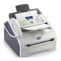
Brother FAX-2825 Service Manual (321 pages)
Facsimile Equipment
Brand:
Brother
| Category:
Fax Machine
| Size: 13.34 MB
Table of Contents
Service Manual
1
How this Manual Is Organized
3
Table of Contents
5
Choosing a Location
12
Chapter 1 Parts Names & Functions
13
Equipment Outline
15
Control Panel
16
Components
19
Chapter 2 Specifications
20
General Specifications
22
General
22
Paper Specifications
23
Printable Area
25
Toner Cartridge Weight Information
29
Specifications List
30
Model Name
36
Chapter 3 Theory of Operation
44
Overview
46
Mechanical Components
47
Scanner Mechanism
48
Document Feeding and Ejecting Mechanism
48
Scanner
48
Printing Mechanism
49
Paper Supply
49
Push-Up Function of Paper Tray
51
Paper Registration
53
Drum Unit
54
Paper Eject
54
Toner Cartridge
55
Print Process
58
Sensors and Actuators
61
Control Electronics
62
Components
62
Chapter 4 Transfer of Data Left in the Machine to be Sent for Repair
65
Transferring Received Fax Data
65
Chapter 5 Disassembly/Reassembly and Lubrication
67
Disassembly/Reassembly
70
Safety Precautions
70
Tightening Torque
71
Preparation
72
How to Access the Object Component
72
Disassembly Flowchart
73
Paper Eject Tray
74
Drum/Toner ASSY
74
Paper Tray
75
Back Cover
76
Rear Chute Cover
77
Document Base ASSY
78
Side Cover L
79
Handset Holder
80
Speaker ASSY
81
Side Cover R/Link Stopper
82
Panel Unit
83
Hook PCB ASSY
89
Top Cover
90
Ncu Pcb Assy
101
Paper Stopper L/S
103
Front Cover
104
Pickup Roller Holder ASSY
105
Fixing Unit
109
High-Voltage PS PCB ASSY
114
Main PCB
115
PS PCB Unit/Fan 40
117
PS PCB Unit/Fan 40
119
Laser Unit
121
Sub Chute ASSY
122
Link Lever
123
Tail Edge Actuator
124
Regist Front Actuator/Regist Front Spring
124
Regist Sensor PCB ASSY
125
Regist Rear Actuator/Regist Rear Spring
125
Fan Motor 60 Unit
126
Toner LED PCB ASSY/LED Holder
127
New Toner Actuator/New Toner Actuator Spring
128
New Toner Sensor Harness ASSY
128
Cover Sensor
129
Toner Sensor PCB ASSY
129
Main Motor ASSY
130
Develop Joint
131
P/R Solenoid ASSY
132
F/R Solenoid ASSY
132
Main Frame L
134
Main Frame R
135
Harness Routing
136
Lubrication
143
Chapter 6 Adjustments and Updating of Settings, Required after Parts Replacement
145
Adjust the Handset Volume (Function Code 16)
146
Adjust the Scan Start/End Positions (Function Code 54)
146
Check the Control Panel PCB for Normal Operation (Function Code 13)
146
Customize the EEPROM on the Main PCB (Function Code 74)
146
If You Replace the Main Pcb
146
Initialize the EEPROM on the Main PCB (Function Code 01)
146
Load Update Programs/Data
146
Make a Sensor Operation Check (Function Code 32)
146
If You Replace the Main Pcb
147
1 ] Load Update Programs/Data
147
2 ] Initialize the EEPROM on the Main PCB (Function Code 01)
147
3 ] Customize the EEPROM on the Main PCB (Function Code 74)
147
4 ] Check the Control Panel PCB for Normal Operation (Function Code 13)
147
5 ] Adjust the Handset Volume (Function Code 16)
147
6 ] Make a Sensor Operation Check (Function Code 32)
147
7 ] Adjust the Scan Start/End Positions (Function Code 54)
147
8 ] Acquire of White Level Data and Set the CIS Scanner Area (Function Code 55)
147
9 ] Setting the Serial Number
148
10 ] Inputting the Adjusted Value of the Laser Scanner
149
11 ] Switch Back to Standby
149
If You Replace the Cis
150
1 ] Acquire of White Level Data and Set the CIS Scanner Area Setting (Function Code 55)
150
If You Replace the Laser Unit
150
1 ] Inputting the Adjusted Value of the Laser Scanner
150
Chapter 7 Cleaning
152
Chapter 8 Maintenance Mode
153
Entry into the Maintenance Mode
155
List of Maintenance Mode Functions
156
List of Maintenance-Mode Functions
156
User-Access to the Maintenance Mode
157
Detailed Description of Maintenance Mode Functions
159
Detailed Description of Maintenance-Mode Functions
159
EEPROM Parameter Initialization (Function Code 01/91)
159
Printout of Scanning Compensation Data (Function Code 05)
160
ADF Performance Test (Function Mode 08)
162
Test Pattern (Function Mode 09)
163
Firmware Switch Setting and Printout
164
Printout of Firmware Switch Data (Function Mode 11)
166
Operation Check of LCD (Function Mode 12)
167
Operational Check of Control Panel PCB (Function Mode 13)
168
Adjustment of Handset Volume (Function Code 16)
169
Sensor Operational Check (Function Mode 32)
170
Received Data Transfer Function (Function Mode 53)
171
Fine Adjustment of Scan Start/End Positions (Function Mode 54)
173
Acquisition of White Level Data and CIS Scanner Area Setting
175
Continuous Print Test (Function Mode 67)
175
EEPROM Customizing (Function Mode 74)
176
Display of the Equipment's Log Information (Function Mode 80)
177
Cancellation of the Memory Security Mode
179
Machine Error Code Indication (Function Mode 82)
179
Output of Transmission Log to the Telephone Line (Function Mode 87)
179
Chapter 9 Error Indication and Troubleshooting
180
Error Indication
182
Equipment Errors
182
1 ] Error Messages Appearing on the LCD
182
Communications Errors
193
Troubleshooting
197
Introduction
197
Precautions
197
Checking Prior to Troubleshooting
197
Troubleshooting Based on Problem Type
198
1 ] Paper Feeding Problems
198
2 ] Software Setting Problems
200
3 ] Malfunction
203
4 ] Image Defects
209
5 ] Incorrect Printout
230
6 ] Network Problem
232
Troubleshooting of the Control Panel
236
Troubleshooting of Fax Functions
238
Serial Number Label
243
Operating Procedure
255
Advertisement
Advertisement
Related Products
Brother FAX-2800
Brother FAX 2820
Brother FAX-2845
Brother FAX-2890
Brother FAX 2800 - B/W Laser - Fax
Brother FAX-2440C
Brother FAX-236
Brother InstaFAX FAX2100M
Brother FAX-202
Brother FAX-270MC
Brother Categories
Sewing Machine
All in One Printer
Printer
Label Maker
Fax Machine
More Brother Manuals
Login
Sign In
OR
Sign in with Facebook
Sign in with Google
Upload manual
Upload from disk
Upload from URL