Sign In
Upload
Manuals
Brands
Brother Manuals
All in One Printer
DCP-L3551CDW
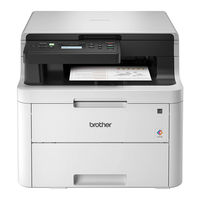
User Manuals: Brother DCP-L3551CDW Laser Printer
Manuals and User Guides for Brother DCP-L3551CDW Laser Printer. We have
4
Brother DCP-L3551CDW Laser Printer manuals available for free PDF download: Service Manual, Reference Manual, Quick Setup Manual
Brother DCP-L3551CDW Service Manual (430 pages)
Brand:
Brother
| Category:
Printer
| Size: 29.45 MB
Table of Contents
Table of Contents
3
Safety Information
11
Chapter 1 Supplemental Specifications
18
General
18
Network Connectivity
24
Service Information
24
Supplies
25
Media Specifications
30
Fax (Only for the Models with Fax Function)
34
Copy
35
Scanner
36
Chapter 2 Error Indication and Troubleshooting
37
Introduction
37
Precautions
37
Checks before Commencing Troubleshooting
39
Overview
41
Cross-Section Drawing
41
Printer Part
41
Scanner Part
43
Paper Feeding
44
Printer Part
44
Scanner Part
46
Operation of each Part and Location of Parts
47
Block Diagram
51
Main Components
52
Error Indications
53
Error Codes
53
Error Message
62
Non Touch Panel Models
62
Touch Panel Models
78
Communication Errors
94
Troubleshooting
98
Error Cause and Remedy
98
Troubleshooting for Paper Feeding Problems
142
No Paper Feeding from T1
142
No Paper Feeding from MP Tray
143
No Paper Feeding from Manual Feed Slot
144
Multiple Sheets of Paper Are Fed
144
Paper Becomes Wrinkled
145
Paper Is Fed at an Angle
145
Paper Curls
145
Unable to Perform 2-Sided Printing
146
Paper Jam
147
Troubleshooting for Image Defects
152
Image Defect Examples
152
Troubleshooting Image Defect
153
Troubleshooting for Software Problems
172
Unable to Receive Data
172
Troubleshooting for Network Problems
173
Cannot Make a Print through Network Connection
173
Cannot Connect to Access Point
173
Troubleshooting for Control Panel Problems
174
Nothing Is Displayed on the LCD
174
Nothing Is Displayed on the LED
174
Unable to Perform Panel Operation
175
Troubleshooting for Toner Cartridge and Drum Unit Problems
176
New Toner Not Detected
176
Toner Cartridge Not Detected
176
Toner Replacement Message Displayed on LCD Is Not Cleared
176
Drum Error
177
Drum Replacement Message Displayed on LCD Is Not Cleared
177
Troubleshooting for Fuser Unit Problems
178
Fuser Unit Failure
178
Troubleshooting for LED ASSY Problems
178
LED ASSY Failure
178
Troubleshooting for PCB Problems
179
Main PCB Failure
179
Full Memory
179
Troubleshooting for Document Feeding Problems
180
No Document Is Fed
180
Multiple Documents Are Fed
180
Document Jam
181
Document Becomes Wrinkled
182
Document Size Is Not Detected Correctly
182
Troubleshooting for Image Defects
183
Defect Examples
183
Troubleshooting According to Image Defect
183
Troubleshooting for Fax Problems
188
Fax Cannot be Sent
188
Fax Cannot be Received
189
Communication Error Occurs
189
Receive Buffer Full During Receiving into Memory
189
Troubleshooting for Other Problems
190
Cannot Make Print
190
Problem of USB Direct Interface
190
Cannot Update Firmware
191
Tray Removed" Message Does Not Disappear
191
Chapter 3 Disassembly/Reassembly
192
Safety Precautions
192
Packing
193
Screw Catalogue
194
Screw Torque List
195
Lubrication
197
Overview of Gears
199
Harness Routing
200
Disassembly Flow
217
Disassembly Procedure
218
Preparation
218
Paper Tray / T1 Separation Pad ASSY
219
Back Cover
220
Rear Flapper Sub ASSY
222
Fuser Cover ASSY / Fuser Unit
223
Cord Hook
228
Side Cover L
229
Side Cover R
230
Back Cover Lower
231
Document Scanner Unit
232
ADF Unit (for Models with ADF)
235
ADF Unit
235
Document Separation Roller ASSY
238
ADF Separation Holder ASSY
240
Second Side CIS Unit / Second Side CIS Flat Cable (Only for Models with Duplex Scanning)
241
Document Detection Sensor PCB / Document Scanning Position Sensor PCB
246
Document Cover ASSY (for Models Without ADF)
247
Panel Unit
249
Key PCB / Panel PCB / Touch Panel ASSY / LCD
250
Panel PCB / LCD ASSY
252
Panel Flat Cable / First Side CIS Unit / First Side CIS Flat Cable
254
Modem Flat Cable / Modem PCB
261
Joint Cover ASSY
262
LED Unit
265
Speaker Unit
267
Nfc Pcb
268
LED Control Flat Cable / LED Control PCB
270
LED ASSY (Y/M/C/K) / LED ASSY Flat Cable (Y/M/C/K)
273
MP Paper Guide ASSY / MP Cover ASSY / USB Host PCB (Only for MP Models)
276
MP Roller Holder ASSY (Only for MP Models)
280
MP Unit (Only for MP Models)
282
Manual Feed Cover ASSY / USB Host PCB (Only for Manual Feed Models)
283
High-Voltage Power Supply PCB / Develop Release Sensor PCB
285
Fan
288
Wlan Pcb
289
Main PCB
290
Cartridge Sensor Relay Flat Cable
292
Develop Release Clutch / Process Drive Unit / High-Voltage Power Supply Flat Cable / Process Motor Flat Cable / Paper Feed Motor Flat Cable
293
T1 Pick-Up Clutch / Registration Clutch / Paper Feed Drive Unit
302
Eject Sensor PCB
304
Roller Holder ASSY
305
Paper Feed Unit
306
Paper Eject ASSY
308
Duplex Tray
309
Low-Voltage Power Supply PCB
310
Registration Mark Sensor L PCB / Registration Mark Sensor R PCB
314
Chapter 4 Adjustments and Updating of Settings, Required after Parts Replacement
316
If You Replace the Main Pcb
316
Configure for Country/Region and Model (Function Code 74)
317
Installing the Firmware (Sub Firmware and Main Firmware)
317
Checking Firmware Version
317
Installing Firmware
318
Initializing the EEPROM of the Main PCB (Function Code 01)
320
Adjusting Touch Panel (Function Code 61)
320
Continuous Adjustments of Density and Registration Sensor (Function Code 73)
320
Acquisition of White Level Data (Function Code 55)
320
Setting the Serial Number (Function Code 80)
320
If You Replace the Registration Mark Sensor Assy or Led Assy
323
Continuous Adjustments of Density and Registration Sensor (Function Code 73)
323
If You Replace the Low-Voltage Power Supply Pcb
324
Resetting Irregular Power Supply Counter of the Low-Voltage Power Supply PCB (Reset Counters for Consumable Parts (Function Code 88))
324
If You Replace the Lcd, Panel Unit or Panel Pcb
325
Adjusting Touch Panel (Function Code 61) (Touch Panel Models Only)
325
Checking LCD Operation (Function Code 12)
325
If You Replace the Adf Unit, First Side Cis Unit, Second Side Cis Unit or Document Scanner Unit
326
Acquisition of White Level Data (Function Code 55)
326
Scanning and Printing Check
326
If You Replace the Fuser Unit
327
Resetting Printed Pages Counter of the Fuser Unit (Reset Counters for Consumable Parts (Function Code 88))
327
If You Replace a Pf Kit
328
Resetting Printed Pages Counter of a PF Kit (Reset Counters for Consumable Parts (Function Code 88))
328
Chapter 5 Service Functions
329
Maintenance Mode
329
How to Enter Maintenance Mode
329
Method of Entering Maintenance Mode for Service Personnel
329
Method of Entering End-User Accessible Maintenance Mode
330
List of Maintenance Mode Functions
331
Details of Maintenance Mode Functions
332
Initialize EEPROM Parameters (Function Code 01, 91)
332
Transition to Shipping State (Function Code 03)
333
ADF Performance Test (Function Code 08)
334
Monochrome Print Quality Test Pattern (Function Code 09)
335
Set Worker Switches (WSW) and Print Worker Switch Setting Data (Function Code 10, 11)
336
Check LCD Operation (Function Code 12)
340
Check Control Panel Key Operation (Function Code 13)
342
Save the Netconfig Information (Function Code 18)
343
Display Software Version (Function Code 25)
344
Check Sensor Operation (Function Code 32)
345
Display LAN Connection Status (Function Code 33)
348
Set PC-Print Functions (Function Code 43)
349
Change USB No. Return Value / Switching Dither Pattern
352
Switching of Black Toner Discharge Compensation (Function Code 45)
352
Adjust Printable Range for each Speed Level (Function Code 46)
361
Transfer Received Fax Data / Log Information (Fax Models Only) (Function Code 53)
363
Fine-Tune Scanning Position (Function Code 54)
365
Acquire White Level Data and Set CIS Scan Area (Function Code 55)
366
Check Consumables Function (Function Code 57)
367
Adjust Touch Panel (Function Code 61)
374
Adjustment of Color Registration (Adjustment of Inter-Color Position Alignment) (Function Code 66)
375
Continuous Print Test (Function Code 67)
380
LED ASSY Test Pattern Print (Function Code 68)
384
Print Frame Pattern (1-Sided Printing) (Function Code 69)
385
Print Frame Pattern (2-Sided Printing) (Function Code 70)
386
Color Test Pattern (Function Code 71)
387
Sensitivity Adjustment of Density Sensor (Function Code 72)
390
Continuous Adjustments of Density / Registration Sensor (Function Code 73)
391
Configure for Country/Region and Model (Function Code 74)
392
Print Maintenance Information (Function Code 77)
397
Check Fan Operation (Function Code 78)
399
Delete Fax Data (Function Code 79)
400
Display Machine Log Information (Function Code 80)
401
Display Machine Error Code (Function Code 82)
406
Developing Bias Voltage Correction (Function Code 83)
407
Send Communication Log Information to Telephone Line (Function Code 87)
408
Reset Counters for Consumable Parts (Function Code 88)
409
Quit Maintenance Mode (Function Code 99)
410
Other Service Functions
411
Change ON/OFF Setting of Color Registration
411
Print Communication Error List
412
Chapter 6 Wiring Diagram
413
Wiring Diagram
413
Chapter 7 Periodical Maintenance
414
Precautions
414
Periodical Replacement Parts
415
Preparation
415
Fuser Unit
416
PF Kit 1
423
PF Kit MP
425
Advertisement
Brother DCP-L3551CDW Reference Manual (20 pages)
Brand:
Brother
| Category:
Printer
| Size: 0.8 MB
Table of Contents
The Online User's Guide Helps You Get the most out of Your Machine
4
Questions or Problems? Take a Look at Our Faqs, Solutions, and Videos Online
5
General Information
6
Control Panel Overview
6
How to Navigate the Touchscreen LCD
9
Touchscreen LCD Overview
10
Load Paper in the Multi- Purpose Tray (MP Tray)
12
Load Paper in the Manual Feed Slot
13
Troubleshooting
14
Identify the Problem
14
Error and Maintenance Messages
15
Document and Paper Jams
16
Solutions for Wireless Connection
16
brother DCP-L3551CDW Quick Setup Manual (2 pages)
Brand:
brother
| Category:
All in One Printer
| Size: 2.67 MB
Table of Contents
Unpack the Machine and Check the Components
1
Load Paper in the Paper Tray
1
Connect the Power Cord and Turn on the Machine
1
Select Your Language (if Needed)
1
Configure the Machine for Faxing (for MFC Models)
1
Connect the Telephone Line Cord (for MFC Models)
1
Select a Device to Connect to Your Machine
2
Connect Your Computer
2
Alternative Wireless Setup
2
Print or Scan Using Your Mobile Device
2
Advertisement
Brother DCP-L3551CDW Quick Setup Manual (2 pages)
Brand:
Brother
| Category:
Printer
| Size: 2.48 MB
Table of Contents
Unpack the Machine and Check the Components
1
Load Paper in the Paper Tray
1
Connect the Power Cord and Turn the Machine on
1
Select Your Language (if Needed)
1
Select a Device to Connect to Your Machine
2
Connect Your Computer
2
Alternative Wireless Setup
2
Print or Scan Using Your Mobile Device
2
Advertisement
Related Products
Brother DCP-L3510CDW
Brother DCP-L3550CDW
Brother DCP-L3517CDW
Brother DCP-L2540DN
Brother DCP-L2560DW
Brother DCP-L6600DW
Brother DCP-L5650DN
Brother DCP-L2535DW
Brother DCP-L2511D
Brother DCP-L2512D
Brother Categories
Sewing Machine
All in One Printer
Printer
Label Maker
Fax Machine
More Brother Manuals
Login
Sign In
OR
Sign in with Facebook
Sign in with Google
Upload manual
Upload from disk
Upload from URL