Sign In
Upload
Manuals
Brands
Brooks Manuals
Chiller
Polycold MaxCool 4000H
Brooks Polycold MaxCool 4000H Manuals
Manuals and User Guides for Brooks Polycold MaxCool 4000H. We have
1
Brooks Polycold MaxCool 4000H manual available for free PDF download: Installation And Operation Manual
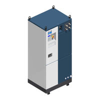
Brooks Polycold MaxCool 4000H Installation And Operation Manual (250 pages)
Cryochiller
Brand:
Brooks
| Category:
Chiller
| Size: 6.14 MB
Table of Contents
Table of Contents
3
Introduction
11
Using this Manual
11
System Illustration
12
System Summary
13
Definitions
13
About the Polycold Maxcool Cryochiller
13
Polycold Cryochiller Versions
14
Theory of Operation
14
Water Vapor Capturing in High Vacuum Systems
15
Minimizing Oil Backstreaming from Diffusion Pumps
16
Heat Removal
17
Polycold Cryochiller System Components
18
Polycold Cryochiller Component List
18
Polycold Cryochiller Views
20
Regulatory Compliance
23
Declaration of Conformity (DOC)
23
Declaration of Incorporation (DOI)
24
Disclosure Table, EIP
25
Limited Warranty
26
Safety
27
Explanation of Hazard Alerts
27
Safety Text
27
Safety Icons
27
Signal Words and Color
28
Alert Example
28
Use of Notes
28
General Guidelines
29
Safety Labels and Safety Label Identification
30
Label Identification and Location
30
Safety and Operational Interlocks
35
Cryochiller Lockout/Tagout
38
Mechanical Hazards
38
Electrical Hazards
40
Thermal Hazards
41
Chemical Hazards
42
High Pressure Gas Hazard
43
Fire and Explosion Hazard
43
Environmental Information
44
Refrigerant Gas Recycling and Disposal
44
Hazardous Materials
44
Material Safety Data Sheets - MSDS
44
Specifications and Site Preparation
45
Physical Specifications
45
Dimensions
46
Site Preparation
47
Access
47
Electrical
48
Electrical Characteristics - Maxcool 4000H and Maxcool 2500L
48
Electrical Protection Requirements - Maxcool 4000H and 2500L
49
Electrical Specification Notes
49
Cooling Water
50
Cooling Water Purity
51
Water Purity Properties
51
Performance Specifications
53
Cryocoils and Refrigerant Lines
54
Balance Pressure
55
Refrigerants in the Maxcool Unit
56
Installation
57
Installation Checklist
58
Installation Overview
59
Component Description
59
Installing a Refrigeration Unit to Meet ASHRAE Requirements
59
Inspect and Unpack the Polycold Cryochiller
60
Move to Location
63
Remove the Compressor Hold-Down Nuts
65
Connect the Cooling Water
66
Connect Electrical Power
69
Input Power Transformers
72
Install the Cryosurface
73
Install the Feed-Through and Cryocoil
73
Install a Cryobaffle
75
Install the Refrigerant Lines
75
Guidelines for Refrigerant Lines
76
Route and Install the Refrigerant Lines
77
Install Parker Ultraseal Compatible Couplings (Standard Fitting)
80
Install Cajon VCR Couplings (Optional Fitting)
81
Route Condensate Drain Tube
82
Check the Refrigerant Line and Cryosurface for Leaks
83
About Leak Check
83
Leak Check Procedure
84
Correct a Leak in a Parker Ultraseal Compatible or Cajon VCR Coupling
87
Evacuate the Refrigerant Line and Cryosurface
88
Connect the Refrigerant Line Thermocouples (Type T)
92
Preliminary Check of the Polycold Cryochiller
95
Insulate Exposed Refrigerant Tubes and Couplings
97
Startup and Test
102
Evaluate the Polycold Cryochiller / Place into Service
104
Install Seismic Restraints
107
Interfacing
109
General Interface Information
109
General Interface Rules
110
RS-232 Interface
110
Gauge Relay (J4)
111
Human Machine Interface - HMI
112
Navigation Keys
112
Cool/Standby/Heat Keys
112
Remote Key
112
Ok Led
112
Fault Leds
113
Reset Button
113
HMI Display
113
HMI Home Screen Display
114
HMI Top Menu
115
System Status
116
Configuration
117
Configuration Page 2
118
Control Parameters
119
Set Comm Parameters
120
Basic Service
121
Ethernet
122
Profibus
123
Devicenet
124
24V DI/DO Remote Interface
125
24 V DI/DO Single Circuit Non-Isolated
128
24 V DI/DO Dual Circuit Non-Isolated
129
24 V DI/DO Single Circuit Isolated
130
24 V DI/DO Dual Circuit Isolated
131
24V DI/DO Remote Installation
132
Operation
133
Introduction
133
System Components
134
Local Controls and Indicators
135
HMI Keypad
135
LED Status Table
137
Single Circuit Modes of Operation
137
Standby
137
Cool
138
Cool Mode Selection
138
Defrost
138
Defrost Mode Selection
138
Dual Circuit Modes of Operation
139
One Circuit Standby and One Circuit Cool
139
One Circuit Defrost and One Circuit Cool
139
One Circuit Defrost Versus One Circuit Standby
139
Compressor Safety Chain
140
Polycold Cryochiller Startup
141
System Boot/Power-Up
141
Compressor Startup
141
Alternate Compressor Startup
141
Operating the Polycold Cryochiller with a Cryocoil
142
Start and Cool the System
142
Defrost the Cryocoil
142
Operating the Polycold Cryochiller with a Cryobaffle
143
Standby and Cool Modes
143
Defrost the Cryobaffle
144
Host Commands
145
Command Group Listing
145
Command Format
146
Response Format
146
Command Terms
147
32 Bit Numbered Bitfield
147
Checksum Calculation
148
Excel Macro for Checksum Calculation
149
Example of Interface Usage
150
Example of a Get Host Command
150
Example of a Set Host Command
150
Set Command Information
151
Security Levels
151
Example of Security Level
152
Command Listing Format
152
Description of the Command
152
Commonly Used Host Commands
152
System Configuration Commands
153
Sw_Ver
153
Software Version & Build Number
153
Vendor_Id
154
Get the Devicenet Vendor ID
154
IP_ADDR IP Address
154
Default_Gateway
154
Network_Mask
155
Devicenet_Params
155
Devicenet Parameters
155
Profibus_Params
156
Profibus Parameters
156
HMI_TIMEOUT HMI Timeout
156
Legacy_Remote,Comp_Signal_Logic
157
Compressor Input Signal Logic
157
Legacy_Remote,Rmt_Signal_Logic
158
Legacy Remote Output Signal Logic
158
Legacy_Remote,Op_Mode_Logic
159
Legacy Remote Operating Mode Logic
159
System Operational State Commands
160
System_Control_Mode_Def
160
Default System Control Mode
160
System_Control_Mode
160
Fault_Status
161
Current Fault Status
161
Alarm_Status
162
Current Alarm Status
162
Active_Alarms
163
Current Active Alarms
163
Capacity_Target_Temp
166
Cooling Capacity Target Temperature
166
Power_Mgmt_Standby_Delay
166
Excess Capacity Temperature Difference
166
E_Mgmt_Enable
167
Energy Management Enable
167
System Sensor Readings
167
Sensor_Snapshot
167
Sensor Data Snapshot
167
System_Valve_State
169
Valve Open/Closed State for System Valves
169
Cldst_Lqd_Temp
169
Unit Coldest Liquid Temperature
169
Cold_Junct_Temp
169
Cold Junction Temperature
169
Buffer_Line_Temp
170
Buffer Line Temperature
170
Warm_Ctl_Temp
170
Rapid Balance Pressure Check Control Temperature
170
System Actions Commands
171
Reset_Alarms
171
SECURITY_LEVEL Security Level
171
Compressor Configuration Commands
172
COMP_SERIAL_NUM Compressor Serial Number
172
Comp_Motor_Hours
172
Refrigerant Motor Operating Hours
172
Compressor Operational State Commands
173
Comp_Motor_State
173
Refrigerant Compressor On/Off State
173
Compressor Sensor Readings
173
Unit_Balance_Press
173
Compressor Static Charge Pressure
173
Comp_Dischrg_Temp
174
Compressor Discharge Temp
174
Comp_Line_Temp
174
Compressor Liquid Line Temperature
174
Comp_Suct_Press
174
Compressor Suction Pressure
174
Comp_Dschrg_Press
175
Compressor Discharge Pressure
175
Circuit Configuration Commands
175
Coldest Liquid Temperature Set Point
175
Setpoint_Relay
176
Setpoint Relay Control
176
Ext_Vac_Contact
177
External Vacuum Device Contact Closure Monitor
177
Defr_Setpt
178
Defrost Complete Set Point
178
Ext_Tc_Enable
178
Enable External Thermocouple
178
Ext_Tc_Alarm
179
External Thermocouple Alarm
179
Circuit Operational State Commands
180
Operating_Mode_Def_Cool
180
Operating_Mode_Def_Defrost
180
Operating_Mode
181
Circuit Sensor Readings Commands
181
Circuit_Valve_State
181
Circ_Inlt_Temp
182
Circ_Otlt_Temp
182
Circ_Feed_Temp
183
Circ_Rtn_Temp
183
Circ_Proc_Ctl_Temp
184
About System Configuration
185
Power Management - Cylinder Unloading
186
Power Management in Standby Mode
186
Power Management in Cool Mode
186
Mode Selection
187
Standby
187
Cool Mode Selection
187
Defrost Mode Selection
187
Alternate Thermocouple Control
187
External Vacuum Control
188
Set Point Relays
188
Remote Control Methods
188
Preventive Maintenance
189
Preventive Maintenance Schedules
190
Troubleshooting
191
Troubleshooting Techniques
191
Define the Problem
191
Contacting Authorized Service
191
Troubleshooting Tables
192
Fault Reporting
192
HMI and Observed Errors
193
Power Troubleshooting
193
Communication Troubleshooting
193
Compressor Motor Troubleshooting
194
Fan Fault Troubleshooting
195
Pressure Related Troubleshooting
196
Temperature Related Troubleshooting
197
Performance Related Troubleshooting
199
Remote Monitor Troubleshooting
200
Bit Mask Value Listing
200
Tools and Parts
207
Tools and Fixtures
207
Parts
208
Parts Shipped with Unit
208
Maintenance Items
208
Optional Parts
209
Appendices
211
Contents
211
Appendix A: Contact Brooks Information
211
Customer Support Information
212
Appendix A: Contact Brooks Information
212
Appendix B: Lifting Rings (Optional)
213
Appendix C: CB2 Excepted Wiring
215
Appendix D: Remote EMO
216
EMO Status
216
EMO Remote Control
216
Remote EMO Connector Wiring
217
Appendix E: Water Vapor Cryotrapping
218
Cryosurface Pumping Efficiency
218
Appendix F: Feedthroughs
220
About Feedthroughs
220
Appendix G: Zero Line Loss Procedure
223
Procedure
223
Appendix H: Rapid Balance Pressure Check
229
Static Pressure Versus Rapid Balance Pressure
229
Rapid Balance Pressure Check Procedure
229
Appendix I: Disconnect, Packing, and Shipping Instructions
230
Packing Procedure
231
Appendix J: Material Safety Data Sheets - MSDS
231
MSDS - Refrigerant Gas
232
MSDS - POE Solest Oil LT-32
239
Glossary
245
Index
250
Advertisement
Advertisement
Related Products
Brooks Polycold MaxCool Series
Brooks Polycold MaxCool 2500L
Brooks 4860
Brooks 4850
Brooks 4800 Series
Brooks FluidX Aperio 4
Brooks PreciseFlex 400
Brooks Categories
Measuring Instruments
Controller
Laboratory Equipment
Security System
Robotics
More Brooks Manuals
Login
Sign In
OR
Sign in with Facebook
Sign in with Google
Upload manual
Upload from disk
Upload from URL