Sign In
Upload
Manuals
Brands
Branson Manuals
Tractor
3515r
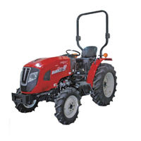
Branson 3515r Manuals
Manuals and User Guides for Branson 3515r. We have
1
Branson 3515r manual available for free PDF download: Owner's Manual
Branson 3515r Owner's Manual (454 pages)
Brand:
Branson
| Category:
Tractor
| Size: 53.63 MB
Table of Contents
Chapter 1 General Information
7
Table of Contents
7
General Information for Service
8
For Safe Operation
8
Work Place
8
Working Clothes and Other Safety Gears
9
Tool
9
Standard Parts, Lubricant, Grease and Oil
10
Finishing Up And Checking
10
Torque Part
10
Electric System
10
Safety During Service
11
Waste Disposal
12
Location of Decals
13
General Information for Maintenance
17
Tightening Torque
17
Hex. Bolt
17
Stud Bolt
17
Oil, Grease, Fuel and Coolant Specifications
18
Electric Device Service
18
Using Standard Part And Adhesive
19
Inspection and Corresponding Action
21
Daily Inspection
21
Checking Work Place
21
Checking Condition Around Tractor
21
Checking When Seating on Driver's Seat
21
Checking When Turning Ignition Switch
21
Checking When Starting Engine
21
General Information for Service
22
Machine History And Information
22
Serial Number
22
Transmission Serial Number
22
Engine Number
22
Hourmeter
22
Components of Tractor
23
Front And Rear Exterior View
23
Interior View
24
Exterior Dimensions
26
Tractor Specifications
26
Major Specifications
27
Driving Speed
29
Periodic Maintenance Schedule Table
30
Periodic Inspection
30
Inspection Description
32
Fueling Into Fuel Tank
32
Checking Engine Oil
33
Checking Coolant Amount
33
Checking Lamps
34
Checking Seat Belt
34
Cleaning Radiator Dust Grill
34
Checking Instrument Cluster Signals
34
Changing Engine Oil
35
Replacing Engine Oil Filter
36
Replacing Hst Filter [Hst Model]
36
Replacing Transmission/Hydraulic Filter
37
Changing Transmission Fluid/Hydraulic Oil
37
Adjusting Clutch Pedal [Mec. Model]
38
Adjusting Brake Pedal
39
Adjusting Fan Belt Tension
39
Checking Fuel Line
40
Cleaning Air Cleaner Element
40
Battery
41
Checking Radiator And Intake Hoses
41
Applying Grease
42
Adding Anti-Freeze
43
Fuse And Relay
44
Tire Inflation Pressure
45
Checking Toe-In
45
Adjusting Front Wheel Toe-In
45
Tightening Wheel Bolt
46
Table of Contents
47
Chapter 2 Engine
49
Exterior and Names of Parts
49
Specification
49
Engine Dimensions
50
Name of each Part
52
Emissions Regulations
53
EPA Emissions
53
The Emissions Certificate
53
Warranty Condition of
54
Main Function and Periodic Check
55
Periodic Checklist
55
Check the Main Function
56
Visual Check
56
Lubricating Oil
56
Fuel
57
Coolant
58
V-Belt
59
Every 50Hrs Check
59
Check Every 250Hrs
59
Check Every 500Hrs
59
Check Every 1,000Hrs
59
Check Every 2,000Hrs
59
Defect Diagnosis and Management
60
DPF Data Logger
65
Installation
65
Dpf System
65
Introduction
65
Signal Lamp
65
Scanner (Fault Diagnosis Device)
65
Logging Data
65
Features (Input / Output)
66
Data Logger Specification
66
Hardware Block Diagram
66
Electric Specification
67
DPS Sensor
67
EGTS Sensor (Exhaust Gas Temperature Sensor)
68
DPF Check LED Lamp
70
CAN Communication
73
PC USB2 Communications
76
Rtc(Real Time Check) Power
76
Running Temperature Range
77
Case: Water-Proof Case
77
Warranty
77
We Guarantee DPF Data Logger
77
Sectional View for Major Components
78
Cylinder Block
78
Gear Case
80
Flywheel Housing and Oil Pan
81
Cylinder Head and Head Cover
82
Intake Manifold
84
Exhaust Manifold
87
Camshaft and Drive Gear
91
Crankshaft and Piston
92
Lubrication System
93
Cooling System
96
Fuel Injection Pump
97
Fuel Injection System and Valve
98
Fuel System
99
Start Motor
101
Alternator and Electric System
102
DPF Application System
103
Dpf's Sensor Option
105
Disassembly and Service
107
Engine Removal
107
Disassembly of Engine
111
General Precautions
111
Lubricating Oil
111
V-Belt, V-Pulley
112
Alternator
112
After-Treatment Device (Atd) [3015R(H)/3515R(H)/4015R(H)]
112
Exhaust Manifold
112
Fuel Injection Pipes
113
Fuel Drain Line
113
Fuel Injection Valve (Injector)
113
Glow Plug
113
Intake Manifold
114
Water Pump
114
Oil Filter
114
Oil Cooler
114
Head Cover
115
Rocker-Arm Shaft
115
Push Rod
115
Cylinder Head
116
Fuel Filter
116
Oil Pan
116
Frame and Oil Suction Pipe
117
Starter
117
Flywheel
117
Mounting Flange
117
Oil Seal Housing
118
Crank Pulley
118
Gear Case
118
Fuel Injection Pump
118
Idle Shaft and Idle Gear
119
Cam Shaft Assembly
119
Oil Pump
119
Gear Case Flange
119
Piston and Connecting Rod
120
Crank Shaft
120
Main Parts Inspection & Maintenance
120
Cylinder Head
122
Cylinder Block
123
Valve Device
123
Piston & Piston Ring
125
Crank Shaft
127
Cam Shaft
128
Gears
129
The Engine Assembly
130
Caution before Assembling the Engine
130
Cylinder Block
130
Crankshaft
130
Piston and Connecting Rod
131
Gear Case Flange
132
Oil Pump
132
Camshaft
133
Injection Pump
133
Idle Gear
134
Gear Case
135
Frame and Oil Suction Pipe
135
Oil Pan
135
Oil Seal Housing
135
Mounting Flange
136
Flywheel
136
Crank Pulley
136
Cylinder Head
137
Push Rod
137
Rocker Arm Assembly
138
Cylinder Head Cover
139
Glow Plug
139
Injection Valve (Injector)
140
Water Pump
140
Intake Manifold
140
Fuel Drain Pipe
140
Fuel Supply Pipe
141
Oil Filter
141
Exhaust Manifold
141
Fuel Filter
141
Starter
142
Alternator
142
V-Belt
142
After-Treatment Device (ATD) [3015R(H)/3515R(H)/4015R(H)]
142
Lubricating System
142
Engine Operation
143
Engine Important Parts Maintenance
144
Electrical System
150
Main Bolt Tightening Torque
156
Maintenance Standard Table
156
Standard Bolt & Nut Tightening Torque
157
Service Data
158
Chapter 3 Clutch [Mec. Model]
163
Overview
164
Sectional View Of Clutch Assembly
164
Clutch Pedal Components
165
Clutch Pedal Play Adjustment
166
Clutch Housing
167
Sectional View for Major Components
167
Clutch Release
169
Clutch Disassembly
170
Park the Tractor on Level Ground and Apply the Hand
170
Clutch Housing Removal
170
Disassembly
170
Table of Contents
173
Chapter 4 Transmission
174
Overview
174
Specification
174
Power Transfer
175
Transmission Assembly Diagram
175
Power Flow Chart
177
Structure and Operating
179
Main Shift
179
F-R Shuttle Shift
182
Range Shift
184
Pto Shift
187
4Wd
189
Rear Axle
190
Power Transfer
190
Operation and Adjustment
191
Differential System
191
Brake
192
Overview
192
Operating Principle Of Brake
194
Brake Pedal Free Play Adjustment
195
Parking Brake Operation
196
Sectional View for Major Components
200
Shaft, F/R Drv [Mec. Model]
200
Main Shift [Mec. Model]
201
Shuttle Ass'y [Mec. Model]
202
Range Shift Gear
203
Main P.t.o Shaft
205
Pto Drive Shaft
207
Fork, Main Shift [Mec. Model]
208
Lever Ass'y, Range Shift
209
Front Drive Shaft
210
4Wd Lever
211
Fork & Lever, Pto
212
Ring Gear & Diff.gear Ass'y
213
Differential
214
Driving Part, Rear Axle
215
Brake
216
Brake Pedal
217
Disassembly and Service
219
Mec. Model
219
Clutch Housing Removal
219
Transmission Case Assembly Disassembly
221
Transmission Case Assembly Components Disassembly
223
Hst Model
230
Clutch Housing Removal
230
Transmission Case Assembly Disassembly
233
Transmission Case Assembly Components Disassembly
234
4WD Shaft Disassembly [MEC. Model/Hst Model]
240
Rear Axle Case Disassembly
241
Rear Axle Drive Section Disassembly
244
Brake Assembly Disassembly
246
Pto Shift Gear Disassembly
248
Differential System Disassembly
249
Chapter 5 Front Axle
253
Overview
254
Specifications
254
Tightening Torque For Major Components
254
Power Transfer
255
Knuckle Section
256
Inspection and Adjustment
257
Toe-In
257
Troubleshooting
258
Center Pin Support
259
Sectional View for Major Components
259
Tie Rod
260
Ring Gear And Differential Gear
261
4Wd Gear Case
262
Spacer
263
Front Drive Shaft
264
Disassembly and Service
265
Front Gear Case
269
Front Axle Case Component Disassembly
269
Front Differential
275
Front Differential Assembly Disassembly
277
Table of Contents
279
Circuit Diagram for Hydraulic System
281
Diagram for Hydraulic System
283
Chapter 6 Hydraulic System
285
Control Valve
285
Hydraulic Pump
285
Major Component Specifications
285
Pst Valve
285
Front Outlet Valve
286
Hst [Hst Model]
286
Pto Valve
286
Rear Scv Valve
286
Hst Filter [Hst Model]
287
Hydraulic Filter
287
Oil Cooler [Hst Model]
287
Pst Cylinder
287
Structure and Operation
288
Steering Valve
288
Overview
288
Internal Structure and Operating Principle
289
Examples Of Steering Wheel Operation
291
Pst Cylinder
294
Hydraulic Pump
295
Pto Valve
296
Rear Scv Valve
298
Front Outlet Valve Assembly
300
Control Valve
302
Operation And Oil Flow
304
Control Lever Operation
308
Hydraulic Cylinder Case Assembly
310
Hydraulic Cylinder Case
310
Safety Valve
311
Stop Valve (Also As Slow Return Valve)
312
Hydraulic Filter And Strainer
313
Hydraulic Filter
313
Hst Filter [Hst Model]
314
Hst(Hydrostatic Transmission)
315
Hst Passage Composition
315
Exterior Dimension
316
Circuit Diagram
317
Hst Pump
318
Hst Motor
318
Charge Relief Valve
319
Neutral Valve
320
Main Relief Valve
323
Hst Pedal And Link
324
Oil Cooler [Hst Model]
327
Position Control
327
Draft Control
328
Troubleshooting
329
Sectional View for Major Components
330
Steering Column
330
Cylinder
331
Pipe
332
Hyd Pump
333
Case, Hyd Cylinder
334
Relief Valve
335
Piston Ass'y
337
Safty Valve
338
Stop Valve
339
Hyd Control Position Type
340
Draft Control
342
Hyd Piping
343
Hyd Filter
344
Hyd Pump [Hst Model]
346
Oil Cooler [Hst Model]
347
Disassembly and Service
348
Hydraulic Cylinder Case Assembly Disassembly and Assembly
348
Control Valve Disassembly
354
Rear Scv Valve Disassembly
360
Pto Valve Disassembly
362
Front Outlet Valve Disassembly
364
Steering Valve Disassembly
365
Hydraulic Pump Disassembly
367
Hst [Hst Model]
369
Relief Valve Block Disassembly
374
Inspection, Adjustment and Test
375
Pst Valve
376
Relief Valve Pressure Test
376
Pto Valve
376
Sequence Valve Pressure Test
376
Front Outlet Valve
377
Relief Valve Pressure Test
377
Hst Neutral Setting [Hst Model]
377
Hst Main Relief Valve Pressure Test
378
Table of Contents
379
Chapter 7 Electric System
381
Major Electric System Specifications
381
Major Electric Component Layout Diagram
383
Electric Wiring Diagram
385
Color Definition
387
Symbol
387
Symbols and Wiring Color Definition in Electric Circuit
387
Battery And Fusible Link
388
Circuit Configuration by Major Function
388
Ignition Switch On
389
Preheat
391
Pto Operation
392
Instrument Cluster And Sensors
394
Combination Switch And Head Lamp
396
Turn Signal Lamp Switch, Hazard Warning Flasher and Flasher Unit
397
[3015R(H)/3515R(H)/4015R(H)]
398
Battery
399
Service Tips
399
Service Tips and Components of Electric System
399
Electric Wiring
400
Fuse
400
Components
401
Ignition Switch
401
Fuse Box
402
Fusible Link
402
Relay 5P
403
Preheat Relay
404
Preheat Controller
405
Flasher Unit
407
Cruise Controller [Hst Model]
408
Safe Start Switch [Mec. Model]
409
Pto Engagement Switch
410
Safety Start Neutral Switch [HST Model]
411
Stop Lamp Switch
411
Starter
412
Alternator
413
Engine Oil Pressure Switch
413
Coolant Temperature Sensor (Preheating)
414
Coolant Temperature Sensor (Meter)
415
Fuel Cut-Off Solenoid
415
Fuel Sensor
416
Glow Plug
416
Combination Switch
417
Horn
417
DPF Logger [3015R(H)/3515R(H)/4015R(H)]
418
Differential Pressure Sensor [3015R(H)/3515R(H)/4015R(H)]
420
Exhaust Gas Temperature Sensor [3015R(H)/3515R(H)/4015R(H)]
420
Instrument Cluster
421
Head Lamp
426
Lamp Bulb Replacement
426
Front Turn Signal Lamp
427
Rear Combination Lamp
429
Main Wiring Diagram
433
Wiring Diagram
433
Bonnet Wiring Diagram (Wiring G)
437
Battery
439
Sectional View for Major Components
439
Switch
441
Fender
443
Hst Pedal [Hst Model]
445
Troubleshooting
446
General Information
449
Engine
451
Transmission
452
Index
453
Advertisement
Advertisement
Related Products
Branson 3015r
Branson 3015h
Branson 3515h
Branson 3120R
Branson 3520R
Branson 3800
Branson 3510
Branson 00 Series
Branson 2000 series
Branson 20R series
Branson Categories
Tractor
Power Supply
Ultrasonic Jewelry Cleaner
Controller
Laboratory Equipment
More Branson Manuals
Login
Sign In
OR
Sign in with Facebook
Sign in with Google
Upload manual
Upload from disk
Upload from URL