Sign In
Upload
Manuals
Brands
Bosch Manuals
Engine
DOK-MOTOR-MCL Series
Bosch DOK-MOTOR-MCL Series Linear Motors Manuals
Manuals and User Guides for Bosch DOK-MOTOR-MCL Series Linear Motors. We have
1
Bosch DOK-MOTOR-MCL Series Linear Motors manual available for free PDF download: Project Planning Manual
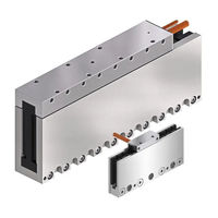
Bosch DOK-MOTOR-MCL Series Project Planning Manual (196 pages)
Ironless Linear Motors
Brand:
Bosch
| Category:
Engine
| Size: 8.99 MB
Table of Contents
Table of Contents
3
1 Rexroth MCL - Product Presentation
9
Fields of Application Ironless Linear Motors
9
Construction Ironless Linear Motors
10
Comparison Ironless with Ferreous Linear Motors
10
Power Spectrum of MCL Motors
11
About this Documentation
12
Document Structure
12
Additional Documentation
12
Standards
13
Additional Components
13
Your Feedback
13
2 Important Instructions on Use
15
Appropriate Use
15
Introduction
15
Areas of Use and Application
15
Inappropriate Use
16
3 Safety Instructions for Electric Drives and Controls
17
Definitions of Terms
17
General Information
18
Using the Safety Instructions and Passing Them on to Others
18
Requirements for Safe Use
18
Hazards by Improper Use
19
Instructions with Regard to Specific Dangers
20
Protection against Contact with Electrical Parts and Housings
20
Protective Extra-Low Voltage as Protection against Electric Shock
21
Protection against Dangerous Movements
22
Protection against Magnetic and Electromagnetic Fields During Operation and Mounting
23
Protection against Contact with Hot Parts
24
Protection During Handling and Mounting
24
Battery Safety
24
Protection against Pressurized Systems
25
Explanation of Signal Words and the Safety Alert Symbol
25
4 Technical Data
27
Explanations about Technical Data
27
Introduction
27
Operating Behavior
27
Description of Specified Sizes
29
General Technical Data
31
Technical Data - Frame Size MCL015
32
Data Sheet MCP015
32
Data Sheet MCS015
32
Motor Characteristic Curve Frame Size 015
33
Technical Data - Frame Size MCL020
34
Data Sheet MCP020
34
Data Sheet MCS020
34
Motor Characteristic Curves Frame Size 020
35
Technical Data - Frame Size MCL030
37
Data Sheet MCP030
37
Data Sheet MCS030
37
Motor Characteristic Curve Frame Size 030
38
Technical Data - Frame Size MCL040
40
Data Sheet MCP040
40
Data Sheet MCS040
41
Motor Characteristic Curves Frame Size 040
42
Technical Data - Frame Size MCL070
44
Data Sheet MCP070
44
Data Sheet MCS070
45
Motor Characteristic Curve Frame Size 070
46
5 Dimension Sheets
49
Installation Tolerances
49
General Information
49
Frame Size MCL015
50
Frame Size MCL020
51
Parallelism and Symmetry of Machine Parts
52
Dimension Sheets MCL015
54
Dimension Sheets MCL020
56
Dimension Sheets MCL030
58
Dimension Sheets MCL040
60
Dimension Sheets MCL070
62
6 Type Codes
65
Type Code Structure and Description
65
General Information
65
Type Code Primary Part MCP
65
Type Code Secondary Part MCS
67
Type Code Frame Size 015
68
Type Code Frame Size 020
70
Type Code Frame Size 030
72
Type Code Frame Size 040
74
Type Code Frame Size 070
76
7 Accessories and Options
79
Hall Unit
79
General Information
79
Hall Unit Functional Princple
79
Hall Unit Assembly/Disassembly
82
Ordering Designation Separate Hall Unit
83
Hall Unit Adapter Box SHL03.1
83
General Functional Principle
83
Order Designation Hall Unit Adapter Box
83
8 Connection Technique
85
Power Connection
85
Connection Cable on Primary Part
85
Assembly Connection Cable on Primary Part
87
Connection Power
88
Installation of Power Connection
90
Sensors
92
Connection Temperature Sensor
92
Connection Hall Unit
92
Assembly Hall Unit Connection Cable
94
Connect Digital Hall Unit
95
Connect Analog Hall Unit
96
Length Measuring System
96
9 Application and Construction Instructions
99
Mode of Functioning
99
Motor Design
99
Design Primary Part
99
Design Secondary Part
100
Frame Size and Frame Length
101
Setup Elevation and Ambient Conditions
102
Ambient Conditions
103
Degree of Protection
104
Acceptances and Approvals
104
CE-Sign
104
Rohs Conformity
104
Magnet Fields
105
Noise Emission
106
Thermal Behavior
106
Motor Temperature Monitoring
109
Feed Force at Reduced Covering between Primary and Secondary Part
110
Requirements on the Machine Design
112
General
112
Mass Reduction
112
Mechanical Rigidity
112
Protection of the Motor Installation Space
114
Thermal Motor Connection
114
Arrangement of Motor Components
114
Single Arrangement
114
Several Motors Per Axis
115
Arrangement of Secondary Parts
120
Vertical Axis
121
Length Measuring System
121
General
121
Selection Criteria for Length Measuring System
121
Linear Guiding Systems
123
Manufacturers of Linear Guiding Systems
123
Braking Systems and Holding Devices
124
End Position Shock Absorber
124
Axis Cover Systems
124
Drive and Control of Indradyn L Motors
125
General
125
Drive Controllers
125
Control Systems
125
Deactivation Upon EMERGENCY Stopand in the Event of a Malfunction
126
General
126
Deactivation by the Drive
126
Deactivation by a Master Control
127
Deactivation Via Mechanical Braking Device
127
Response to a Mains
127
Short-Circuit of DC Bus
129
Position and Velocity Resolution
129
Drive Internal Position Resolution and Position Accuracy
129
Velocity Resolution
130
10 Motor-Controller-Combinations
131
General Information
131
Motor-Controller-Combinations with Nyce 4000
131
Motor-Controller-Combinations with Indradrive Cs
132
11 Motor Dimensioning
133
General Procedure
133
Basic Formulae
134
General Movement Equations
134
Feed Forces
135
Average Velocity
138
Trapezoidal Velocity Profile
139
Triangle-Shaped Velocity Profile
143
Sinusoidal Velocity Profile
144
Duty Cycle and Feed Force
147
General Information
147
Determining the Duty Cycle
147
Determining the Drive Power
148
General Information
148
Rated Output
148
Maximum Output
149
Power Loss
150
Energy Regeneration
150
Efficiency
151
Thermal Connection of MCL Motors on the Machine
151
Operation at or Near Motor Standstill
154
12 Handling, Transport and Storage
155
Identification of the Motor Components
155
Primary Part
155
Secondary Part
156
Delivery Status and Packaging
157
Primary Parts
157
Secondary Parts
157
Checking the Motor Components
157
Factory Checks of the Motor Components
157
Transport and Storage
158
Notes about Transport
158
Notes about Storage
159
13 Installation
161
Basic Precondition
161
Arrangement of Motor Components
161
Installation of Motor Components
162
Air-Gap, Parallelism and Symmetry of the Motor Components
162
Fastening Secondary Part
163
Fastening the Primary Part
165
Electrical Connection
166
14 Commissioning, Operation and Maintenance
167
General Information for Startup of Ironless Indradyn L Motors
167
General Requirements
167
General Information
167
Checking All Electrical and Mechanical Components
167
Tools
168
General Start-Up Procedure
168
Parameterization
170
General Information
170
Entering Motor Parameters
170
Entering Length Measuring System Parameter
170
Entering Drive Limitations and Application-Related Parameters
171
Determining the Polarity of the Linear Scale
172
Commutation Adjustment
173
General Information
173
Sinusoidal Procedure
175
Hall Sensor Procedure
175
Measuring Procedure: Measuring the Reference between Primary and Secondary Part
176
Setting and Optimizing the Control Loop
178
General Procedure
178
Parameterization and Optimization of Gantry Axes
181
Estimating the Moved Mass Using a Velocity Ramp
182
Maintenance and Check of Motor Components
184
General Information
184
Check of Motor and Auxiliary Components
184
Electrical Check of Motor Components
184
Operation with Third-Party Controllers
185
Environmental Protection and Disposal
185
Environmental Protection
185
Disposal
185
15 Service and Support
187
Index
189
Advertisement
Advertisement
Related Products
bosch DHG6015NUC
Bosch DOMESTIC HOT WATER HEAT PUMP
Bosch Single Door
Bosch Dome Easy II IPV
Bosch DOW 1171
Bosch Door/window contact II
Bosch Door/Window Contact II +M
Bosch DWHD440MFP
Bosch Divar16
Bosch DHI642EQ
Bosch Categories
Dishwasher
Washer
Oven
Power Tool
Dryer
More Bosch Manuals
Login
Sign In
OR
Sign in with Facebook
Sign in with Google
Upload manual
Upload from disk
Upload from URL