Sign In
Upload
Manuals
Brands
Beckhoff Manuals
Touch terminals
TwinSAFE EL6910
Beckhoff TwinSAFE EL6910 Manuals
Manuals and User Guides for Beckhoff TwinSAFE EL6910. We have
2
Beckhoff TwinSAFE EL6910 manuals available for free PDF download: Operation Manual
Beckhoff TwinSAFE EL6910 Operation Manual (144 pages)
Logic Terminal
Brand:
Beckhoff
| Category:
Touch terminals
| Size: 7.59 MB
Table of Contents
Table of Contents
3
1 Foreword
5
Notes on the Documentation
5
Safety Instructions
6
Delivery State
6
Operator's Obligation to Exercise Diligence
6
Description of Safety Symbols
7
Documentation Issue Status
8
Version History of the Twinsafe Product
9
References
10
2 Twinsafe System Description
11
Extension of the Beckhoff I/O System with Safety Functions
11
Safety Concept
11
3 Product Description
12
EL6910 - Twinsafe Logic Terminal
12
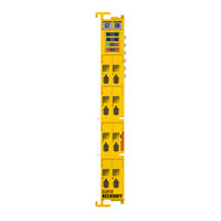
Fig. 1 EL6910 - Twinsafe Logic Terminal
12
Intended Use
13
Technical Data
15
Safety Parameters
16
Dimensions
17
Fig. 2 Dimensions of the EL6910
17
4 Operation
18
Environmental Conditions
18
Installation
18
Safety Instructions
18
Transport / Storage
18
Mechanical Installation
18
Fig. 3 Installation Position and Minimum Distances
19
Fig. 4 Sample Configuration for Temperature Measurement
20
Fig. 5 Installation on the Mounting Rail
21
Fig. 6 Removal from Mounting Rail
22
Fig. 7 Thermally Unfavorable Arrangement of the Twinsafe Terminals
24
Electrical Installation
25
Fig. 8 Thermally Favorable Arrangement of the Twinsafe Terminals
25
Fig. 9 PE Power Contact
26
Fig. 10 EL6900/EL6910 Pin Assignment
27
Twinsafe Reaction Times
28
Fig. 11 Typical Reaction Time
28
Fig. 12 Worst-Case Reaction Time
29
Operation in Potentially Explosive Atmospheres (ATEX)
30
Special Conditions
30
Identification
30
Date Code and Serial Number
31
Further ATEX Documentation
31
Configuration of the Terminal in Twincat
32
Configuration Requirements
32
Adding an Ethercat Coupler
32
Adding an Ethercat Terminal
32
Adding an EL6910
32
Fig. 13 Adding an EL6910
33
Address Settings on Twinsafe Terminals with 1023 Possible Addresses
34
Fig. 14 Address Settings on Twinsafe Terminals with 1023 Possible Addresses
34
Creating a Safety Project in Twincat 3
35
Fig. 15 Creating a Safety Project - Add New Item
35
Fig. 16 Creating a Safety Project - Project Name and Directory
35
Fig. 17 Twincat Safety Project Wizard
36
Fig. 18 Selecting the Target System Node
36
Fig. 19 Linking of Target System and Twinsafe Terminal
37
Fig. 20 Starting the Automatic Import from the I/O Configuration
37
Fig. 21 Selection from the I/O Tree
38
Fig. 22 Creating Alias Devices by the User
38
Fig. 23 Alias Device in the Safety Project Structure
39
Fig. 24 Links to EL6910/EJ6910 Process Image
39
Fig. 25 Connection-Specific Parameters
39
Fig. 26 Selecting an Alias Device
40
Fig. 27 Safety Parameter for the Device
41
Fig. 28 AX5000 Safety Drive Functions
41
Fig. 29 AX5000 Safety Drive Options - General AX5805 Settings
42
Fig. 30 AX5000 Safety Drive Options - Process Image
42
Fig. 31 AX5000 Safety Drive Options - Function Diagram
43
Fig. 32 Creating an External Connection (Custom Fsoe Connection)
44
Fig. 33 Parameterization of the Process Image Size
44
Fig. 34 Renaming the Individual Signals Within the Telegram
45
Fig. 35 Selecting the Variables
45
Fig. 36 Direct Linking with the Process Image of an Ethercat Terminal
46
Fig. 37 Connection-Specific Parameters
46
Fig. 38 Function Blocks Available for EL6910/EJ6910
48
Fig. 39 Function Block on the SAL Worksheet
48
Fig. 40 Dragging a Connection between Two Function Blocks
49
Fig. 41 Connection between Two Function Blocks
50
Fig. 42 Creating a Network
50
Fig. 43 Change Link
51
Fig. 44 Dialog for Selecting a Suitable FB Port
51
Downloading the Safety Application
63
Online Mode
67
New Features in TC3.1 Build 4022
70
Info Data
89
Info Data for the Connection
89
Info Data for Function Blocks
91
Info Data for the Twinsafe Group
92
Info Data for the Device
93
Version History
93
User Administration
94
Backup/Restore
97
Export/Import of the Safety Project
100
Diag History Tab
102
Fig. 137 Importing a Safety Project
102
Fig. 138 Diag History
102
Configuration of the Profisafe Slave
103
Fig. 139 Diag History - Advanced Settings
103
Fig. 140 Creating a Custom Profisafe Connection
104
Fig. 141 Process Image
104
Configuration of the Slave Connection in the Profisafe Master Software
105
Fig. 142 Safe Address Setting
105
Fig. 143 Connection Setting
105
Configuration of the PROFINET Device
106
Fig. 144 Configuration of the Slave Connection in the Profisafe Master Software
106
Fig. 145 Configuration of the PROFINET Device
106
Sample Program for Parameterizationin the Following Sample Program the Parameter Data
107
Fig. 146 Protocol AMS Netid of the PROFINET Device
107
Are Received, Stored in the PLC as Persistent Data, Resent to the EL6910 Whenever the Device Starts Up, and Stored in Coe Object 0X8005
107
Configuration of the Profisafe Master
109
Fig. 147 Creating a Custom Profisafe Connection
109
Fig. 148 Setting the Process Image Size
109
Fig. 149 Setting the Safe Address
110
Fig. 150 Selecting the Profisafe Master
110
Valid Profisafe Configurations
111
Fig. 151 Parameters for the Profisafe Master Connection
111
Invalid Profisafe Configurations
112
Fig. 152 Valid Profisafe Configuration - Sample 1
112
Fig. 153 Valid Profisafe Configuration - Sample 2
112
Twinsafe SC Configuration
113
Fig. 154 Invalid Profisafe Configuration - Sample 1
113
Fig. 155 Invalid Profisafe Configuration - Sample 2
113
Fig. 156 Adding the Twinsafe SC Process Data under the Component, E.g. EL5021-0090
114
Fig. 157 Twinsafe SC Component Process Data, Example EL5021-0090
114
Fig. 158 Adding a Twinsafe SC Connection
114
Fig. 159 Creating a Link to Twinsafe SC Terminal
115
Fig. 160 Selecting a Free CRC
115
Fig. 161 Selecting the Process Data Size and the Process Data
116
Fig. 162 Selection of the Process Data
116
Fig. 163 Coe Objects 0X8010:01 and 0X8010:02
116
Customizing / Disabling Twinsafe Groups
117
Fig. 164 Entering the Safety Address and the CRC
117
Fig. 165 Properties of the Twinsafe Group
118
Fig. 166 Replacement Values for the Twinsafe Group
118
Fig. 167 Login
119
Fig. 168 Customizing Twinsafe Groups
119
Fig. 169 Customized Twinsafe Group
119
Saving the Analog Group Inputs Persistently
120
Fig. 170 Specifying Deviations for Analog Input Values
120
Fig. 171 Activate Saving of All Analog Group Inputs
120
Project Design Limits of EL6910/EJ6910
121
Sync-Manager Configuration
121
Fig. 172 Overlapping Sync Manager
122
Fig. 173 Ethercat Advanced Settings
122
Fig. 174 Sync Manager Settings
123
Fig. 175 Setting the Start Address for SM3
123
Diagnostics
124
Diagnostic Leds
124
Fig. 176 EL6910 Diagnostic Leds
124
Status Leds
125
Fig. 177 EL6910 Status Leds
125
Diagnostic Objects
126
Cycle Time of the Safety Project
127
Diagnosis History
127
Fig. 178 Diagnostic Object: FSLOGIC Status (F100Hex) in the Process Image of the Twinsafe Compo- Nent
127
Fig. 179 ESI/XML Message Text
129
Fig. 180 Startup List
129
Maintenance
130
Service Life
131
Decommissioning
131
Fig. 181 Unique Serial Number of a Twinsafe Terminal
131
Firmware Update of Twinsafe Products
132
5 Appendix
135
Support and Service
135
Certificates
136
EN 81-20, en 81-22 and en 81-50
138
List of Illustrations
140
Advertisement
Beckhoff TwinSAFE EL6910 Operation Manual (105 pages)
TwinSAFE Logic Terminal
Brand:
Beckhoff
| Category:
Touch terminals
| Size: 5.22 MB
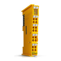
Table of Contents
Table of Contents
3
1 Foreword
5
Notes on the Documentation
5
Safety Instructions
6
Delivery State
6
Operator's Obligation to Exercise Diligence
6
Description of Safety Symbols
7
Documentation Issue Status
8
2 Twinsafe System Description
9
Extension of the Beckhoff I/O System with Safety Functions
9
Safety Concept
9
3 Product Description
10
EL6910 - Twinsafe Logic Terminal
10
Fig. 1 EL6910 - Twinsafe Logic Terminal
10
Intended Use
11
Technical Data
12
Safety Parameters
13
Dimensions
14
Fig. 2 Dimensions of the EL6910
14
4 Operation
15
Environmental Conditions
15
Installation
15
Safety Instructions
15
Transport / Storage
15
Mechanical Installation
15
Fig. 3 Installation Position and Minimum Distances
16
Fig. 4 Sample Configuration for Temperature Measurement
17
Fig. 5 Installation on the Mounting Rail
18
Electrical Installation
19
Fig. 6 Removal of Mounting Rails
19
Fig. 7 PE Power Contact
20
Fig. 8 Connection of a Cable to a Terminal Point
21
Fig. 9 EL6900/EL6910 Pin Assignment
22
Twinsafe Reaction Times
23
Fig. 10 Typical Reaction Time
23
Fig. 11 Worst-Case Reaction Time
24
Operation in Potentially Explosive Atmospheres (ATEX)
25
Special Conditions
25
Identification
25
Date Code and Serial Number
25
Further ATEX Documentation
26
Configuration of the Terminal in Twincat
26
Configuration Requirements
26
Adding an Ethercat Coupler
26
Adding an Ethercat Terminal
26
Adding an EL6910
26
Fig. 12 Adding an EL6910
27
Address Settings on Twinsafe Terminals with 1023 Possible Addresses
28
Fig. 13 Address Settings on Twinsafe Terminals with 1023 Possible Addresses
28
Creating a Safety Project in Twincat 3
29
Fig. 14 Creating a Safety Project - Add New Item
29
Fig. 15 Creating a Safety Project - Project Name and Directory
29
Fig. 16 Twincat Safety Project Wizard
30
Fig. 17 Selecting the Target System Node
30
Fig. 18 Linking of Target System and Twinsafe Terminal
31
Fig. 19 Starting the Automatic Import from the I/O Configuration
31
Fig. 20 Selection from the I/O Tree
32
Fig. 21 Creating Alias Devices by the User
32
Fig. 22 Alias Device in the Safety Project Structure
33
Fig. 23 Links to the EL6910/EJ6910 Process Image
33
Fig. 24 Connection-Specific Parameters
33
Fig. 25 Selecting an Alias Device
34
Fig. 26 Safety Parameters of the Device
35
Fig. 27 AX5000 Safety Drive Functions
35
Fig. 28 AX5000 Safety Drive Options - General AX5805 Settings
36
Fig. 29 AX5000 Safety Drive Options - Process Image
36
Fig. 30 AX5000 Safety Drive Options - Function Diagram
37
Fig. 31 Creating an External Connection (Custom Fsoe Connection)
38
Fig. 32 Parameterization of the Process Image Size
38
Fig. 33 Renaming the Individual Signals Within the Telegram
39
Fig. 34 Selecting the Variable
39
Fig. 35 Direct Linking with the Process Image of an Ethercat Terminal
40
Fig. 36 Connection-Specific Parameters
40
Fig. 37 Function Blocks Available for EL6910/EJ6910
42
Fig. 38 Function Block on the Sal Worksheet
42
Fig. 39 Dragging a Connection between Two Function Blocks
43
Fig. 40 Connection between Two Function Blocks
44
Fig. 41 Creating a Network
44
Fig. 42 Change Link
45
Fig. 43 Dialog for Selecting a Suitable FB Port
45
Fig. 44 Link Display
45
Downloading the Safety Application
56
Online Mode
59
Info Data
64
Info Data for the Connection
64
Info Data for Function Blocks
65
Info Data for the Twinsafe Group
66
Info Data for the Device
67
Version History
68
User Administration
68
Backup/Restore
71
Export/Import of the Safety Project
74
Diag History
75
Configuration of the Profisafe Slave
77
Configuration of the Slave Connection in the Profisafe Master Software
79
Configuration of the PROFINET Device
79
Sample Program for Parameterization
80
Configuration of the Profisafe Master
82
Valid Profisafe Configurations
84
Invalid Profisafe Configurations
85
Twinsafe SC Configuration
86
Customizing / Disabling Twinsafe Groups
90
Saving the Analog Group Inputs Persistently
93
Project Design Limits of EL6910/EJ6910
93
Diagnostics
94
Diagnostic Leds
94
Led Indicators
95
Status Leds
96
Diagnostic Objects
97
Cycle Time of the Safety Project
98
Maintenance
98
Service Life
99
Decommissioning
99
5 Appendix
100
Support and Service
100
Certificates
101
List of Illustrations
103
Advertisement
Related Products
Beckhoff EL6900
Beckhoff EL6900Z
Beckhoff EtherCAT EL6752
Beckhoff EL6601
Beckhoff EL6614
Beckhoff EL6751
Beckhoff EL6652-00 0 Series
Beckhoff EL6652-0000
Beckhoff EL6652-0010
Beckhoff EL6731
Beckhoff Categories
Touch terminals
Industrial PC
Control Unit
Touch Panel
Industrial Equipment
More Beckhoff Manuals
Login
Sign In
OR
Sign in with Facebook
Sign in with Google
Upload manual
Upload from disk
Upload from URL