Sign In
Upload
Manuals
Brands
Bard Manuals
Controller
MC5600
Bard MC5600 Lead/Lag Controller Manuals
Manuals and User Guides for Bard MC5600 Lead/Lag Controller. We have
2
Bard MC5600 Lead/Lag Controller manuals available for free PDF download: Installation And Operation Instructions With Replacement Parts List
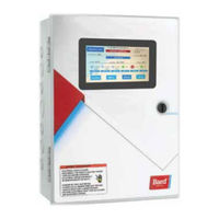
Bard MC5600 Installation And Operation Instructions With Replacement Parts List (68 pages)
Brand:
Bard
| Category:
Controller
| Size: 2.41 MB
Table of Contents
Table of Contents
4
General Information
6
Shipping Damage
6
General
6
Theory of Operation
6
Controller Certifications
6
Getting Other Information and Publications
6
Control System
7
Controller and Accessories
7
Optional Sensors
7
Installation
8
FIGURES and TABLES Figure 1 Typical MC5000 Component Location
8
MC5000 Series Controller
9
Mounting the MC5000 Series Controller
9
Figure 2 MC5000 Controller Dimensional Drawing
9
Figure 2
9
Installing Remote Temperature Sensor(S)
10
Figure 3 Controller Grounding Lugs
10
Figure 4 Optional Remote Temperature Sensor Installation
10
Engineered Features
11
Touch Screen
11
Figure 5 MC5000 Series Touch Screen Interface
11
Main Control Board (MC5300 and MC5600)
12
Secondary Control Board (MC5600 Only)
13
Main Alarm Board (MC5300-BC and MC5600-BC)
14
Secondary Alarm Board (MC5600-BC Only)
15
Setup
16
Guided Setup
16
MC5000 Equipment Setup Menu Descriptions
16
MC5000 Controller System Setup Menu Descriptions
16
Equipment Setup Menu
16
System Setup Menu
17
Date/Time Setup Menu
17
Comfort Mode
17
System Status
17
Cooling Set Points
17
Heating Set Points
17
Comfort Mode Cooling Set Points
17
Comfort Mode Heating Set Points
18
Dehumidification Level Set Points
18
Humidification Level Set Points
18
Cooling Interstage Differential Set Points
18
Cooling Stage off Differential Set Points
18
Heating Interstage Differential Set Points
18
Heating Stage off Differential Set Points
18
Dehumidification Interstage Differential Set Points
18
Dehumidification Stage off Differential Set Points
18
Humidification Interstage Differential Set Points
19
Humidification Stage off Differential Set Points
19
High Humidity Alarm Set Points
19
Low Humidity Alarm Set Points
19
Low Temperature Alarm Level Set Points
19
High Temperature Alarm Level 1 Set Points
19
High Temperature Alarm Level 2 Set Points
19
Heat Pump Lockout Range Set Points
19
Operation
20
Basic Controller Specifications/Features
20
Temperature Sensors
20
Temperature Sensor Logic
20
Basic Controller Input/Output Specifications
21
Alarm Board Specifications/Features
21
MC5000 Alarm Board I/O
21
Alarm Board Contacts
21
MC5000B W/Enhanced Version Alarm Board
22
Plus MC5000A Inputs/Outputs
22
Low Voltage Field Wiring
22
Controller Grounding
22
Controller Power-Up
22
Emergency off
22
Staging Delay Periods
22
Blower Operation
22
Pre-Purge
22
Pre-Purge Setup
22
Lead/Lag Rotation
23
Cooling Sequence of Operation
23
Heating Sequence of Operation
23
Electric Heat
23
Heat Pumps
23
Humidity Control Option
26
Dehumidification Sequence
26
Figure 6 Mechanical Dehumidification
26
Mechanical Sequence
26
Humidification Operation
27
Synchronized Sequence
27
Staging
27
Figure 7 Synchronized Dehumidification
27
Staging Sequence
27
Adjustable Interstage Differential
28
Adjustable off Differential
28
Cooling Staging
28
Cooling with Economizer
28
Figure 8 Heating Staging
28
Figure 9 Cooling with Six Single Stage Units (W/Economizers)
28
Heating Staging
28
Figure 10 Cooling with Six Single Stage Units (W/Economizers) Using Twinning/Pairs Option
29
Figure 11 Cooling with Six Single Stage Units (W/Economizers) Using Twinning/Triples Option
29
The Advantages of Twinning: Pairs
29
The Advantages of Twinning: Triples
29
Humidification/Dehumidification Demand Staging
30
Alternating/Non-Alternating Set up
30
Alternating
30
Alternating/Non-Alternating Logic
30
Non-Alternating
30
Figure 12 Alternating Sequence Cooling
31
Figure 13 Non-Alternating Sequence Cooling
31
Figure 14
32
Twinning: Simultaneous Unit Operation
32
Figure 15
33
Triples: Simultaneous Unit Operation
33
Alarm Functionality
34
Test Mode
36
Manual Test
36
Self Test
36
Network/Remote Connectivity
36
Remote Connectivity
36
Setup
36
Touch Screen Display IP Configuration
36
Figure 17
37
Webpage IP Configuration
37
Figure 18
38
Navigational Side Pane
38
Webpages
38
Modbus
39
Connections Diagrams
44
Figure
44
And no Ventilation W/Balanced Climate
44
No Ventilation or Balanced Climate
45
Figure 21
47
No Ventilation W/Balanced Climate
48
Figure 22
48
W**H Series Unit W/Economizer
50
Figure 24
50
Figure 26
52
Figure 27
53
2-Stage W*SA* Series Unit W/Economizer
53
Figure 28
54
Figure 29
55
Figure 30
56
Troubleshooting
57
Humidity Sensor (8408-059)
57
Figure 31
57
Verifying Sensor LED Is Illuminated
57
Sufficient Airflow Across Remote Sensor
57
Checking Remote Temperature Sensor 8301-095
58
Troubleshooting Alarms
59
MC5000 Replacement Parts List
61
Advertisement
Bard MC5600 Installation And Operation Instructions With Replacement Parts List (55 pages)
Brand:
Bard
| Category:
Controller
| Size: 1.68 MB
Table of Contents
Table of Contents
2
General Information
4
Shipping Damage
4
General
4
Theory of Operation
4
Controller Certifications
4
Getting Other Information and Publications
4
Cooling System
5
MC5000 Series Controller and Accessories
5
Installation
6
Figure 1
6
MC5000 Series Controller
7
Figure 2 MC5000 Controller Dimensional Drawing
7
Mounting the MC5000 Series Controller
7
Figure 3 Controller Grounding Lugs
8
Figure 4 Optional Remote Temperature Sensor Installation
8
Installing Remote Temperature Sensor(S)
8
FIGURES and TABLES Figure 1 Typical MC5000 Component Location
6
Engineered Features
9
Touch Screen
9
Figure 5 MC5000 Series Touch Screen Interface
9
Main Control Board (MC5300 and MC5600)
10
Secondary Control Board (MC5600 Only)
11
Main Alarm Board (MC5300-BC and MC5600-BC)
12
Secondary Alarm Board (MC5600-BC Only)
13
Setup
14
Guided Setup
14
MC5000 Equipment Setup Menu Descriptions
14
MC5000 Controller System Setup Menu Descriptions
14
Equipment Setup Menu
14
System Setup Menu
15
Date/Time Setup Menu
15
Comfort Mode
15
System Status
15
Cooling Set Points
15
Heating Set Points
15
Comfort Mode Cooling Set Points
15
Comfort Mode Heating Set Points
16
Dehumidification Level Set Points
16
Humidification Level Set Points
16
Cooling Interstage Differential Set Points
16
Cooling off Differential Set Points
16
Heating Interstage Differential Set Points
16
Heating Stage off Differential Set Points
16
Dehumidification Interstage Differential Set Points
16
Dehumidification Stage off Differential Set Points
16
Humidification Interstage Differential Set Points
17
Humidification Stage off Differential Set Points
17
High Humidity Alarm Set Points
17
Low Humidity Alarm Set Points
17
Low Temperature Alarm Level Set Points
17
High Temperature Level 1 Alarm Set Points
17
High Temperature Level 2 Alarm Set Points
17
Heat Pump Lockout Range Set Points
17
Operation
18
Basic Controller Specifications/Features
18
Temperature Sensors
18
Temperature Sensor Logic
18
Basic Controller Input/Output Specifications
19
Alarm Board Specifications/Features
19
MC5000 Alarm Board I/O
19
Alarm Board Contacts
19
MC5000B W/Enhanced Version Alarm Board
20
Plus MC5000A Inputs/Outputs
20
Low Voltage Field Wiring
20
Controller Grounding
20
Controller Power-Up
20
Emergency off
20
Staging Delay Periods
20
Blower Operation
20
Pre-Purge
20
Pre-Purge Setup
20
Lead/Lag Rotation
21
Humidity Control Option
24
Dehumidification Sequence
24
Figure 6 Mechanical Dehumidification
24
Mechanical Sequence
24
Humidification Operation
25
Synchronized Sequence
25
Staging
25
Figure 7 Synchronized Dehumidification
25
Staging Sequence
25
Adjustable Interstage Differential
26
Adjustable off Differential
26
Cooling Staging
26
Cooling with Economizer
26
Figure 10 Cooling with Six Single Stage Units (W/Economizers) Using Twinning/Pairs Option
26
Figure 8 Heating Staging
26
Heating Staging
26
Figure 9 Cooling with Six Single Stage Units (W/Economizers)
27
The Advantages of Twinning: Pairs
27
The Advantages of Twinning: Triples
27
Cooling with Six Single Stage Units (W/Economizers) Using Twinning/Triples Option
27
Figure 10
27
Alternating/Non-Alternating Set up
28
Alternating
28
Alternating/Non-Alternating Logic
28
Figure 12
28
Non-Alternating
28
Cooling Without Economizer
28
Humidification/Dehumidification Demand Staging
28
Alternating Sequence Cooling
29
Figure 13
29
Non-Alternating Sequence Cooling
29
Twinning: Simultaneous Unit Operation
30
Figure 15
30
Triples: Simultaneous Unit Operation
31
Cooling Sequence of Operation
31
Heating Sequence of Operation
31
Electric Heat
31
Figure
31
Heat Pumps
31
Alarm Functionality
32
Test Mode
34
Manual Test
34
System Test
34
Network/Remote Connectivity
34
Remote Connectivity
34
Setup
34
Touch Screen Display IP Configuration
34
Webpage IP Configuration
35
Navigational Side Pane
36
Webpages
36
Modbus
37
Connections Diagrams
42
Troubleshooting
52
Checking Remote Temperature Sensor 8301-095
52
Troubleshooting Alarms
53
MC5000 Replacement Parts List
55
Advertisement
Related Products
Bard MC5000 Series
Bard MC5300
Bard MC500 Series
Bard MC4002-B
Bard MC4002-BC
Bard MC4000-B
Bard MC4000-BC
Bard MC4001 Series
Bard MC4000-AC
Bard MC4000-A
Bard Categories
Air Conditioner
Heat Pump
Medical Equipment
Furnace
Controller
More Bard Manuals
Login
Sign In
OR
Sign in with Facebook
Sign in with Google
Upload manual
Upload from disk
Upload from URL