Sign In
Upload
Manuals
Brands
Bailey Manuals
Music Mixer
infi 90 Modular Power System II
Bailey infi 90 Modular Power System II Manuals
Manuals and User Guides for Bailey infi 90 Modular Power System II. We have
7
Bailey infi 90 Modular Power System II manuals available for free PDF download: Instruction, Hardware Manual
Bailey infi 90 Modular Power System II Instruction (124 pages)
Brand:
Bailey
| Category:
Power Supply
| Size: 2.51 MB
Table of Contents
Safety Summary
5
Table of Contents
8
Section 1 - Introduction
13
Overview
13
Modular Power System II Front View (Typical)
13
Intended User
14
Power System Description
14
System Power Module
14
Field Power Modules
14
Power Monitor Module
15
Power Module Chassis
16
Power Entry Circuit Breaker or Switch
16
Fan Chassis and System Fans
16
Block Diagram of Input Power for N, N+1 and N+X Redundant Systems
17
Block Diagram of Input Power for 2N Redundant Systems
17
Features
18
Instruction Content
18
How to Use this Instruction
19
Reference Documents
19
Glossary of Terms and Abbreviations
19
Nomenclature
20
Specifications
20
Introduction
21
Introduction
24
Section 2 - Description and Operation
21
Reference Documents
32
Glossary of Terms and Abbreviations
33
Specifications
37
Modular Power System II Architecture
39
Power Entry
40
Power Distribution
40
System Cooling
41
Power Module/Bus Bar Requirements
41
Power Monitor Module
42
IPCHS01 Backplane Bus Bars and Connectors
42
AC/DC Inputs
43
Status Signal Block Diagram
43
Power Monitor Module Status
44
Power Module Monitoring
44
System Bus and I/O Voltage Monitoring
44
Fan and Temperature Monitoring
45
Auxiliary and Status Inputs
45
Power Modules
46
IPSYS01 Status Signals
47
IPFLD Field Power Module Status Signals
47
Section 3 - Installation
48
Introduction
48
Special Handling
48
Unpacking and Inspection
49
Power System Installation
49
Installing System Power Cables
50
Connecting System Power Cables
50
Chassis Mounting
51
IPFCH01 Power Fan Chassis Mounting
51
IPCHS01 Power Module Chassis Mounting
52
Clip Nut Spacing
52
Installing the Fan Assembly
53
Power Entry Circuit Breaker or Switch and Fan Assembly Installation (Side View)
53
Fan Cable Part Numbers
53
Power Entry Circuit Breaker or Switch Installation (Rear View)
54
Example Mounting Sequence (IPMON01, IPSYS01, IPFLD01, IPBLK01, IPFLD125)
55
Power Entry Circuit Breaker or Switch
56
System Power Wiring (Completion)
58
Ac Safety Ground Wiring
60
Installing the Power Monitor Module
60
Ac/DC Feeder Lines
61
Dipswitch SW1
62
Dipswitch SW2
63
IPMON01 Circuit Board Layout
63
Dipswitch SW3
64
IPMON01 Dipswitch SW1 Settings
64
IPMON01 Dipswitch SW2 Settings
64
IPMON01 Dipswitch SW3 Settings
65
Dipswitch SW4
66
Dipswitch SW5
66
IPMON01 Dipswitch SW4 Settings
66
IPMON01 Input Voltage Jumper Settings
67
IPMON01 Auxiliary Input Trip Points Jumper Settings
67
SECTION 3 - INSTALLATION (Continued)
67
IPMON01 Dipswitch SW5 Settings
67
IPMON01 Temperature Trip Point Jumper Settings
68
IPMON01 Status Inputs Jumper Settings
68
IPMON01 Auxiliary Input Trip Points Jumper Settings
68
IPMON01 Temperature Trip Points Jumper Settings
68
Installing the Power Modules
69
IPMON01 Status Inputs Jumper Settings
69
Installing Blank Faceplates
71
IPSYS01 Circuit Board Layout
71
Section 4 - Operating Procedures
72
Introduction
72
Leds
72
Power Monitor Module
72
IPMON01 Faceplate Leds
73
Power System and Field Modules
74
IPSYS01, IPFLD01, IPFLD24, IPFLD48 and IPFLD125 LED States
74
Test Points
75
Power Fail Interrupt Reset Pushbutton
75
IPSYS01 and IPFLD Faceplate Leds
75
Section 5 - Troubleshooting
76
Introduction
76
Troubleshooting Procedures
76
IPSYS01 and IPFLD Field Modules LED Troubleshooting Procedures
76
IPMON01 Status Leds Troubleshooting Procedures
77
IPMON01 Alarm Leds Troubleshooting Procedures
78
Section 6 - Maintenance
81
Introduction
81
Preventive Maintenance Schedule
81
Equipment Required
82
Preventive Maintenance Procedures
82
Cabinet Filter Cleaning and Replacement
82
Checking Connections
83
Checking Power Module Outputs
84
Printed Circuit Board Cleaning
84
General Cleaning and Washing
85
Edge Connector Cleaning
85
Section 7 - Repair and Replacement Procedures
87
Introduction
87
Spare Parts
87
Spare Part Numbers or Nomenclatures
87
Power Monitor Module
88
Module Replacement
88
Fuse Replacement
89
Module Replacement
89
Power Modules
90
Fuse Replacement
91
Power System Fan
91
Fan Assembly Replacement
94
Fuse Replacement
94
Power Entry Circuit Breaker or Switch Replacement
95
Power Module Chassis Replacement
96
Fan Chassis Replacement
100
Section 8 - Support Services
102
Introduction
102
Replacement Parts and Ordering Information
102
Training
102
Technical Documentation
102
Ipmon01 Dipswitch and Jumper Settings
103
IPMON01 Dipswitch SW1 Settings
103
IPMON01 Dipswitch SW2 Settings
103
IPMON01 Dipswitch SW3 Settings
104
IPMON01 Dipswitch SW4 Settings
104
IPMON01 Dipswitch SW5 Settings
105
IPMON01 Input Voltage Jumper Settings
105
IPMON01 Auxiliary Input Trip Points Jumper Settings
105
IPMON01 Temperature Trip Points Jumper Settings
105
Appendix A - Quick Reference Guide
106
Ipmon01 Led States
106
IPMON01 Status Inputs Jumper Settings
106
IPSYS01 and IPFLD LED STATES
107
Appendix B - Sizing the Power System
108
Introduction
108
Calculating System Current Requirements
109
Calculating I/O Current Requirements
109
DC Current Consumption for INFI 90 OPEN Modules
110
VDC Current Consumption of Termination Units or Modules
111
System and I/O Current Capacities
112
Sizing the Modular Power System II
112
System Current Capacity
112
Maximum Power Entry Circuit Breaker or Switch Current Draw
115
Example Sizing Calculation
116
Example Cabinet Current Draw Calculation
117
Introduction
118
Appendix C - Wiring Diagrams
119
2N Redundancy System Wiring Diagram
119
N, N+1 and N+X Redundancy System Wiring Diagram
120
Advertisement
Bailey infi 90 Modular Power System II Instruction (92 pages)
INFI-NET to Computer Interfaces
Brand:
Bailey
| Category:
Desktop
| Size: 1.75 MB
Table of Contents
Table of Contents
7
Section 1 - Introduction
12
Overview
12
Intended User
12
Computer Interface Description
12
INICI01 INFI-NET to Computer Interface
12
INICI03 INFI-NET to Computer Interface
12
Module Description
13
INNIS01 Network Interface Slave Module
13
INICI01 and INICI03 INFI-NET to Computer Interfaces
13
INICT01 INFI-NET to Computer Transfer Module
14
INICT03 INFI-NET to Computer Transfer Module
14
Features
15
Instruction Content
16
How to Use this Manual
16
Glossary of Terms and Abbreviations
17
Reference Documents
17
Nomenclature
17
Specifications
18
Nomenclature
18
Section 2 - Description and Operation
20
Introduction
20
Module Integrity
20
Innis01 Network Interface Slave Module
21
Exception Reports
21
Messages
21
Broadcast
21
Time Synchronization
21
Multicast
21
NIS Poll
21
Message Format
21
Message Transmission
22
NIS Data Integrity
22
Retry Logic
22
Node Status Table
22
Polling
22
Inict01 Infi-Net to Computer Transfer Module
23
Inict03 Infi-Net to Computer Transfer Module
23
Infi-Net to Computer Interface Commands
24
Data Acquisition
24
Configuration
25
Process Control
25
System Status
25
Section 3 - Installation
26
Introduction
26
Special Handling
26
Unpacking and Inspection
27
Innis01 Network Interface Slave Module Configuration
27
Dipswitch Settings
27
INNIS01 Module Dipswitch and Jumper Locations
27
Dipswitch SW1 - Node Address
28
Dipswitch SW2 - Loop Address
28
Dipswitch SW3 - Loop Mode
28
INNIS01 Module Dipswitch SW2 Settings
28
NNIS01 Module Dipswitch SW1 Settings
28
Dipswitch SW4 - I/O Module Address and Counters
29
INNIS01 Module Dipswitch SW3 Settings
29
INNIS01 Module Address Settings
30
INNIS01 Module Event Counters
30
Jumper Settings
31
INNIS01 Module Error Counters
31
Power System Status
32
SECTION 3 - INSTALLATION (Continued)
32
Innis01 Module Installation
32
INNIS01 Module Jumper Settings
32
Inict01 Infi-Net to Computer Transfer Module Configuration
33
Dipswitch Settings
34
Dipswitch U72 - Options
34
INICT01 Module CPU Circuit Board Dipswitch Locations
34
INICT01 Module Dipswitch U72 Settings
34
Dipswitch U73 - Serial Port Communication Rate
35
INICT01 Module Dipswitch U73 Settings
35
Dipswitch U75 - Diagnostics
36
Inict01 Module Installation
36
INICT01 Module Dipswitch U75 Settings
36
Inict03 Infi-Net to Computer Transfer Module Configuration
38
Dipswitch Settings
38
INICT03 Module Dipswitch and Jumper Locations
38
Dipswitch SW1 - Serial Port Communication Rate
39
Dipswitch SW2 - Diagnostics
39
Dipswitch SW3 - SCSI Port
39
INICT03 Module Dipswitch SW1 Settings
39
Dipswitch SW4 - Options
40
INICT03 Module Dipswitch SW2 Settings
40
INICT03 Module Dipswitch SW3 Settings
40
Jumper Settings
41
INICT03 Module Dipswitch SW4 Settings
41
HW SETUP Socket Jumper
42
Immpi01 Multi-Function Processor Interface Module Configuration
42
Jumper Settings
43
IMMPI01 Module Jumper Locations
43
IMMPI01 Module Jumper J1 Settings
43
Inict03 and Immpi01 Module Installation
44
IMMPI01 Module Jumper J2 Settings
44
Section 4 - Operating Procedures
46
Introduction
46
Innis01 Network Interface Slave Module Start-Up Procedures
46
Event Counters
46
Error Counters
46
INICT01 INFI-NET to COMPUTER TRANSFER MODULE Leds and CONTROLS
46
Status LED
47
CPU Leds
47
Memory Leds
47
INNIS01 Module Faceplate Leds
47
INNIS01 Module Error Codes
48
INNIS01 Module Edge Connector P1 Pin Assignments
50
INNIS01 Module Edge Connector P2 Pin Assignments
50
INNIS01 Module Edge Connector P3 Pin Assignments
50
INICT01 Module Edge Connector P1 Pin Assignment
51
INICT01 Module Edge Connector P2 Pin Assignments
51
INICT01 Module Edge Connector P3 Pin Assignments
51
INICT01 and INICT03 Module Error Codes
52
INICT03 Module Edge Connector P1 Pin Assignment
52
INICT03 Module Edge Connector P2 Pin Assignments
52
INICT03 Module Edge Connector P3 Pin Assignments
52
IMMPI01 Module Edge Connector P1 Pin Assignment
53
IMMPI01 Module Edge Connector P3 Pin Assignments
53
Stop Switch
54
Reset Switch
54
INICT01 Module Faceplate Leds and Controls
54
INICT01 Module Status LED States
54
Inict03 Infi-Net to Computer Transfer Module Leds and Controls
55
Status LED
55
INICT03 Module Faceplate LEDS and Controls
55
INICT03 Module Status LED States
55
CPU Leds
56
Stop/Reset Pushbutton
56
Inici01 and Inici03 Modes of Operation
56
Execute Mode
56
Error Mode
56
Security Functions
56
Hardware Checks
57
Software Checks
57
Utilities
57
TALK90 Option
57
Example INICT03 Module Utilities Menu
58
Example INICT01 Module Utilities Menu
58
Example TALK90 Command Menu
59
Configure/View Callup Password Option
60
Computer Command/Reply Sequences Option
60
Set Local Time and Date Option
60
Monitor Mode Option
61
Real Value Conversion Option
61
RESTART and DEMAND MODULE STATUS Commands and Replies
61
Example Time Utilities Menu
62
Port Address Option
63
Dump on Halt Option
63
Time Sync Accuracy Option
63
Preventive Maintenance Schedule
64
Spare Parts List
70
A-1. NTCL01 Connector and Jumper Locations (Revision F or Greater
71
A-2. NTCL01 Coaxial Cable Connections to INNIS01 Modules
72
A-3. NTCL01 Twinaxial Cable Connections to INNIS01 Modules
72
NTCL01 Jumper Settings for Revision D and E
73
NTCL01 Jumper Settings for Revision F or Greater
73
B-1. NICL01 Connector and Jumper Locations (Revision D or Greater
74
B-2. NICL01 Coaxial Cable Connections to INNIS01 Modules
75
B-3. NICL01 Twinaxial Cable Connections to INNIS01 Modules
75
NICL01 Jumper Settings for Revision C
76
NICL01 Jumper Settngs for Revision D or Greater
76
NIMF01/02 Dipshunt Configuration for Direct Connection to a Host Computer
77
NIMF01/02 Dipshunt Configuration for Direct Connection to a Modem
78
NIMF01/02 Dipshunt Configuration for Direct Connection to Mainframe Computer
79
NIMF01/02 Dipshunt Configuration for Diagnostic Terminal
80
D-5. NIMF01/02 DB-25 Connector Pin Assignments and RS-232-C Signals
81
DTE Jumper Configuration for NTMP01 Termination Unit
82
DCE Jumper Configuration for NTMP01 Termination Unit
83
E-3. NTMP01 Nonhandshake Jumper Configuration
83
E-4. NTMP01 Loopback Jumper Configuration
84
NTMP01 Jumpers J3 through J10 Configuration
84
NTMP01 Jumpers J14 through J17 Configuration
85
DTE Jumper Configuration for NIMP01 Termination Module
86
DCE Jumper Configuration for NIMP01 Termination Module
87
NIMP01 Jumpers J5 through J10 Configuration
88
NIMP01 Jumpers J14 through J17 Configuration
88
Bailey infi 90 Modular Power System II Hardware Manual (103 pages)
Operator Interface Console
Brand:
Bailey
| Category:
Music Mixer
| Size: 1.97 MB
Table of Contents
Table of Contents
8
Section 1 - Introduction
13
Overview
13
Intended User
13
Oic Description
13
IIOIC4221 Console Model
14
IIOIC421 Tabletop Model
14
IIOIC423 Environmental Model
15
CPU (Central Processing Unit)
16
IIOIC421 Tabletop Console
16
IIOIC4221 and IIOIC4222 Console
16
IIOIC423 Environmental Cabinet
16
IIOIC42 Models
16
IIOIC424 Panel Mounted
17
Instruction Content
17
How to Use this Instruction
17
Glossary of Terms and Abbreviations
18
Reference Documents
18
Nomenclature
19
Oic Console Specifications
19
Hardware Nomenclature
19
Introduction
20
Introduction
21
OIC Console Specifications
21
Section 2 - Description and Operation
22
Introduction
22
OIC Communication Levels
22
Oic Console Functional Operation
23
IIOIC42 Block Diagram
23
Section 3 - Installation
24
Introduction
24
Special Handling
24
Unpacking and Inspection
25
Installation Procedure
26
Ac Power Wiring Guidelines
26
Oic Installation
27
OIC Wiring Color Codes
28
IIOIC421 Tabletop Installation and Setup
29
IOIC421 Tabletop Wiring Connections and Cabling
29
IIOIC421 Tabletop (19-Inch) Dimensions
30
IIOIC421 Tabletop Connections (Keyboard Interface Assembly)
30
IIOIC421 Tabletop Cable Connections
31
IIOIC422 Console Setup and Installation
32
IIOIC422 Console Dimensions
33
IIOIC422 Console Keyboard Table
34
IIOIC422 Console 15 Degree Wedge Dimensions
34
IIOIC422 Console Wiring Connections and Cabling
35
IIOIC422 Console 45 Degree Wedge Dimensions
35
IIOIC422 Console Power Entry Panel Connections
36
IIOIC422 Console Cable Connections
37
IIOIC423 Environmental Setup and Installation
39
IIOIC423 Environmental Cabinet Dimensions
39
IIOIC423 Environmental Wiring Connections and Cabling
40
IIOIC423 Environmental Cabinet Anchoring Dimensions
40
IIOIC423 Cable Connections
41
IIOIC423 Environmental Cabinet Power Entry Panel Connections
41
IIOIC423 Environmental Cabinet Cable Connections
42
IIOIC424 Panel Mount Installation and Setup
43
IIOIC424 Panel Mount Dimensions
43
Engineering Keyboard
44
IIOIC424 Panel Mount Wiring Connections and Cabling
44
Operator Interface Devices
44
Operator Keyboard
44
IIOIC424 Panel Mount Power Entry Panel Connections
44
IIOIC424 Panel Mount Cable Connections
45
IIOIC424 Panel Mount Connections
45
IIADP01 Annunciator Display Panel
47
IIATB05 Trackball and IIAMS04 Mouse
47
Engineering Keyboard
47
IIADP02 Annunciator Display Panel
48
IIADP01 Board Connections
48
IIADP01 Annunciator Display Panel SW1 Settings
48
NADS03 Annunciator Display Panel
49
IIADP02 Annunciator Display Panel
49
Touch Screen
50
Touch Screen Nomenclature
50
NADS03 Annunciator Display Panel SW1 Settings
50
Controller Board Installation
51
Touch Screen Installation
51
Touch Screen Parts
51
Calibrating the Touch Screen
52
Touch Screen Jumper and Switch Settings
52
Touch Screen Controller Card Connections
52
Peripherals
53
Software Installation and Start-Up
54
Reference Documents
54
Troubleshooting Guide
55
Section 4 - Troubleshooting
55
Diagnostic Power up Tests
56
DC Power Test
57
Section 5 - Maintenance
58
Preventive Maintenance Schedule and Check List
59
Equipment and Tools Required
59
Standard Preventive Maintenance Procedures
60
Cleaning the Operator Keyboard
61
Cleaning Edge Connector
62
Checking and Inspecting Power Entry Panel
63
Section 6 - Component Description and Replacement
64
IIMKM02A Multibus Keyboard Module
65
Section 6 - Component Description and Replacement
66
Iimkm02A Multibus Keyboard Module Replacement
66
IIOIC422 Multibus Card Cage (Front View)
67
IIOIC422 Multibus Card Cage (Rear View)
68
Fan Assembly for the Card Cage
68
DC Distribution Board Socket Connections
69
DC Distribution Board Pin Outs
69
Connections to DC Distribution Board
69
Power Supply Removal for IIOIC421 Tabletop Console
70
Power Supply Removal for IIOIC422 Consoles
71
IIOIC422 Console
71
Power Supply Removal for IIOIC423 Environmental Console
72
IIOIC423 Environmental Cabinet
72
Power Supply Removal for IIOIC424 Panel Mount Console
73
IIOIC422 Console
74
Power Entry Panel (PEP) Removal for IIOIC422 Consoles
75
IIOIC423 Environmental Cabinet
75
Power Entry Panel (PEP) Removal for IIOIC423 Environmental Cabinet
76
IIOIC424 Panel Mount
76
Power Entry Panel Removal for IIOIC424 Panel Mount
77
Operator Interface Devices
77
IIOIC422 Console Model
78
IIOIC421 Tabletop Model
78
Annunciator Display Panel
78
IIOIC423 Environmental Model
79
IIOIC424 Panel Mounted Model
79
NADS03 Removal from IIOIC423 Environmental Cabinet
80
Keyboard Interface Assembly
80
Keyboard Interface Assembly (IIOIC422 Model)
81
IIOIC421 Tabletop Model
82
IIOIC422 Console
82
IIOIC423 Environmental Model
83
IIOIC424 Panel Mounted Model
83
Operator Keyboard
83
Keyboard Interface Assembly Removal for IIOIC422 Consoles
83
Color Monitor Connections
84
IIOIC422 Console Model
86
Iioic424 Panel Mounted Model
87
MONITOR Assembly
87
Cpu Removal
88
CPU Removal for IIOIC421 Tabletop Console
89
IIOIC423 Environmental Cabinet
90
CPU Removal for IIOIC422 Consoles
90
CPU Removal for IIOIC423 Environmental Console
91
IIOIC424 Panel Mount
91
CPU Assembly
92
CPU Removal for IIOIC424 Panel Mount Console
92
Peripherals
93
CPU Connector Identification
93
Section 7 - Support Services
94
Replacement Parts and Ordering Instructions
94
Training
94
Technical Documentation
94
Spare Parts
94
Recommended Spare Parts
95
Appendix A - Quick Reference Information
96
IIMKM02A Multibus Keyboard Module
96
Keyboard Interface Connector Board
97
A-4. Color Monitor
98
A-6. IIADP01, IIADP02 and NADS03
99
Advertisement
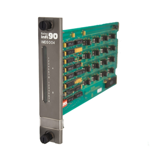
Bailey
Infi 90
Instruction
Bailey infi 90 Modular Power System II Instruction (100 pages)
AC Modular Power System
Brand:
Bailey
| Category:
Power Supply
| Size: 1.91 MB
Table of Contents
Table of Contents
9
Section 1 - Introduction
13
Overview
13
Hardware Description
13
Power Entry Panel
13
Fan Assembly
13
Power Modules
14
Power Mounting Units
14
Module Mounting Units
14
User Qualifications
14
Instruction Content
14
How to Use this Manual
15
Reference Documents
16
Nomenclature
16
Glossary of Terms and Abbreviations
16
Specifications
17
Section 2 - Description and Operation
20
Introduction
20
Modular Power System Architecture
20
Power Distribution
21
Power Entry Panel
21
IEPEP01 and IEPEP02 Panels
21
IEPEP03 Panel
21
AC Transfer Module
22
Bus Monitor Module
22
Fan Assembly
23
Module Mounting Unit
23
Power Mounting Units
23
Power Modules
23
Status Signals
24
Power System Status
24
Power Distribution to the IEPAS02 System Power Module
24
Bus Voltage Status
25
Power Module Status
25
IEPAS02 Module Converter and Status Circuitry
25
Customer Alarm Outputs
26
Status Signal Block Diagram
26
Section 3 - Installation
27
Introduction
27
Unpacking and Inspection
27
Special Handling
27
General Handling
28
Circuit Breakers CB1/CB2
29
Iepep03 Power Entry Panel Wiring
31
AC Transfer Module
31
AC Transfer Module, Switch S1
31
IEPEP03 Power Entry Panel, Rear View
32
Bus Monitor Module
33
Bus Monitor Module Switch Settings
34
Bus Monitor Module Jumper Settings
34
Fan Assembly
35
Power Modules
35
Recommended Power Module Layout for Module Mounting Unit
36
IEPAF02 and IEPAS02 Power Module Board Layout
37
IEPAS02 and IEPAF02 Power Module Jumper Settings
37
Iepep01 and Iepep02 Power Entry Panel Wiring
38
Iepmu01 and Iepmu02 Power Mounting Unit Installation
39
Rear of IEPEP01 and IEPEP02 Power Entry Panels
39
Required Tools
40
Installation in the INFI 90 Cabinet
40
Heat Shrink Tubing for 5 VDC Connection
41
Heat Shrink Tubing for 24 VDC Connection
42
IEPAF02 Power Modules
43
Section 4 - Operating Procedures
44
Introduction
44
SECTION 4 - OPERATING PROCEDURES (Continued)
44
Led Indicators
44
AC Transfer Module
44
Bus Monitor Module
44
Power Module
45
Status Leds, AC Transfer and Bus Monitor Modules
45
Removing Atm or Bmm Modules During Operation
46
Recommended Start-Up Procedures
46
Unloaded DC Bus Output Voltage Requirements
47
Section 5 - Troubleshooting
48
Introduction
48
Troubleshooting Flowcharts
48
IEPEP01 and IEPEP02 Systems
48
IEPEP03 Systems
48
Troubleshooting Flowchart, IEPEP01 and IEPEP02 Power Entry Panels
49
Troubleshooting Flowchart, IEPEP03 Power Entry Panel
52
Section 6 - Maintenance
55
Introduction
55
Preventive Maintenance Schedule
56
Equipment Required
57
Preventive Maintenance Procedures
57
Cabinet Filter Cleaning/Replacement
57
Checking Connections
58
Checking Power Module Outputs
59
Checking Bus Voltages on IEPEP01 and IEPEP02 Systems
59
Checking Bus Voltages on IEPEP03 Systems
59
Power Entry Panel Inspection and Check
60
Printed Circuit Board Cleaning
60
General Cleaning and Washing
61
Edge Connector Cleaning
61
Cleaning Female Edge Connectors
62
Section 7 - Repair/Replacement Procedures
63
Introduction
63
Spare Parts
63
Nomenclature
63
Spare Part Numbers and Description
63
Ac Transfer Module Replacement
64
Bus Monitor Module Replacement
65
Fan Assembly
65
Fuse Replacement
65
Fan Assembly Replacement
65
Power Module
66
Power Module Replacement
67
Power Module Fuse Replacement
67
Power Entry Panel Replacement
68
Section 8 - Support Services
69
Introduction
69
Replacement Parts and Ordering Information
69
Training
69
Technical Documentation
69
Appendix A - Quick Reference Guide
70
Introduction
70
Appendix B - Module Power Requirements
72
Introduction
72
Calculating Current Requirements
73
B-1. DC Current Consumption for INFI 90 Modules
73
Sizing the Modular Power System
76
Sizing Systems with IEPAS02 Modules Only
76
System Calculation Example Using IEPAS02 Modules Only
77
For Systems Using both IEPAS02 and IEPAF02 Modules
78
System Calculation Example Using IEPAS02 and IEPAF02 Modules
80
Maximum Power Entry Panel Current Draw
81
Appendix C - Wiring Diagrams
82
Introduction
82
IEPEP03 Power Entry Panel and Module Mounting Unit Wiring Diagram
83
IEPEP03 Power Entry Panel and Power Mounting Unit Wiring Diagram
84
C-3. IEPEP01/IEPEP02 Power Entry Panel and Module Mounting Unit Wiring Diagram
85
C-4. IEPEP01/IEPEP02 Power Entry Panel and Power Mounting Unit Wiring Diagram
86
Appendix D - Retrofitting the Modular Power System
87
Introduction
87
Network 90 Power System Removal
88
Required Tools
88
Power Entry Panel Removal
88
I/O Power Panel Removal
89
Module Power Panel Removal
89
Fan Assembly Removal
90
Installing the INFI 90 Power System
90
Wiring the INFI 90 Power System
91
Network 90 Cabinet
91
Wiring Diagram of IEPEP03 Power Entry Panel and Power Mounting Unit
93
Wiring Diagram of IEPEP01 and IEPEP02 Power Entry Panel and Power Mounting Unit, Network 90 Cabinet
94
Appendix E - Iepas01/Iepaf01 Power Module Replacement
95
Introduction
95
Replacing Power Modules
95
Power System Sizing
95
Load Sharing
95
IEPAS01/IEPAS02 Modules Power and Current Outputs
95
System Effects on Module Leds
96
Bailey infi 90 Modular Power System II Instruction (48 pages)
Quick Response Slave Module
Brand:
Bailey
| Category:
Control Unit
| Size: 1.18 MB
Table of Contents
Table of Contents
7
Section 1 - Introduction
10
Overview
10
Intended User
10
Module Description
10
Features
11
INFI 90 Communication Levels
11
Instruction Content
12
How to Use this Manual
12
Glossary of Terms and Abbreviations
13
Specifications
14
Reference Documents
16
Nomenclature
16
Section 2 - Description and Operation
17
Introduction
17
Quick Response Slave Module Block Diagram
17
Analog I/O
18
Analog Inputs
18
IMQRS02 Analog Input and Output Circuit
18
Analog Input Circuit Calibration
19
Analog Outputs
19
Digital I/O
19
Digital Inputs
20
Digital Outputs
20
IMQRS02 Digital Input and Output Circuits
20
Digital I/O Buffer
21
I/O Circuit Connections
21
Slave Expander Bus
21
Universal Slave Expander Bus Interface
21
Module Data
22
I/O Data
22
Status Data
22
Logic Power
23
Bus Fault Timer
23
Status Led Indicator
23
Section 3 - Installation
24
Introduction
24
Special Handling
24
Unpacking and Inspection
24
Setup/Physical Installation
25
Slave Address Selection Switch (S1)
25
Quick Response Slave Module
25
Address Select Switch (S1)
25
Analog Output Default Switch (S2)
26
Address Switch Settings (S1)
26
Analog Output Mode Switch (S3)
27
Analog Output Default Switch (S2)
27
Analog Output Default Switch (S2) Settings
27
Digital Input Jumper Settings
28
Analog Output Mode Switch (S3)
28
Analog Output Mode Switch (S3) Settings
28
Termination Unit/Module Configuration
29
Physical Installation
29
Wiring Connections and Cabling
30
Wiring
30
Cable Connections
30
IMQRS02 Cable Connections and Termination
30
Fusing
31
Pre-Operating Adjustments
31
Section 4 - Operating Procedures
32
Introduction
32
Module Status Indicator
32
IMQRS02 Front Panel
32
IMQRS02 Status LED Indicator
32
Start-Up Procedures
33
Section 5 - Troubleshooting
34
Introduction
34
Error Indications and Corrective Action
34
Status LED
34
Master Module Errors
34
Status LED Indications and Corrective Actions
34
Analog Input Reference Error
35
Missing Slave Module Error
35
Module Pin Connections
36
P1 Power Pin Connections
36
P2 Slave Expander Bus Connections
37
P3 I/O Pin Connections
37
Section 6 - Maintenance
38
Introduction
38
Maintenance Schedule
38
Section 7 - Repair/Replacement Procedures
39
Introduction
39
Module Repair/Replacement Procedures
39
Section 8 - Support Services
40
Introduction
40
Replacement Parts and Ordering Information
40
Training
40
Technical Documentation
40
Appendix A - Termination Unit (Ntcs02)Configuration
41
Introduction
41
NTCS02 Dipshunt for Analog Inputs
41
NTCS02 Dipshunt for Analog Outputs
42
NTCS02 Dipshunt for Digital Inputs
43
NTCS02 Dipshunt Configuration
44
Appendix B - Termination Module (Nics01) Configuration
46
Introduction
46
Bailey infi 90 Modular Power System II Instruction (54 pages)
Multi-Function Controller Termination Unit
Brand:
Bailey
| Category:
Controller
| Size: 1.43 MB
Table of Contents
Table of Contents
7
Section 1 - Introduction
10
Overview
10
Transfer Module
10
Example Redundant TMF Application
10
Example Plant Loop to Computer Interface Module Application
11
Intended User
12
Hardware Description
12
Features
12
Example Plant Loop to Plant Loop Application
12
Instruction Content
13
How to Use this Manual
13
Glossary of Terms and Abbreviations
13
Reference Documents
14
Nomenclature
14
Specifications
15
NTMF01 Termination Unit Specifications
15
Section 2 - Installation
16
Introduction
16
Special Handling
16
Unpacking and Inspection
17
Setup/Physical Installation
17
Dipshunt Configuration for DTE or DCE Devices
18
Dipshunt Configuration for a Mainframe Computer
18
Dipshunt Configuration for the INPPT01 Module
18
TMF Unit Connector Assignments and Dipshunt Locations
18
Sequential Events Recorder
19
Dipshunt Configuration for Direct Connection to Host Computer (IMMFC03 and ICT Modules)
19
Installing the Termination Unit
20
Installing the Fuse
20
Dipshunt Configuration for Direct Connection to Modem (MFC and ICT Modules)
20
Mounting the Termination Unit
21
Cable Installation
21
Termination Unit Cables
21
Dipshunt Configuration for Diagnostic Terminal (MFC and ICT Modules)
21
Dipshunt Configuration for Direct Connection to Mainframe Computer (ICT Module)
22
RS-232-C Communication Cable
23
Dipshunt Configuration for PPT Module Acting as DTE (Requires Modem or Other DCE)
23
Serial Extension Cable
24
Dipshunt Configuration for Direct Connection of Local PPT Module Acting as DTE
24
Dipshunt Configuration for Direct Connection of Remote PPT Module Acting as DCE
25
Dipshunt Configuration for Diagnostic Terminal (PPT Module)
26
Dipshunt Configuration for Rochester 3800 and ESA Control SER-740
26
Dipshunt Configuration for Rochester ISM
27
Mounting and Securing the Termination Unit on the Field Termination Panel
27
TMF Cable Applications, Connections and Length Requirements
28
Cable Connections with Redundant MFC Modules, Serial Link to a Station and Serial Ports
28
Power Wiring
29
Section 3 - Maintenance
31
Introduction
31
Maintenance Schedule
31
Section 4 - Repair/Replacement Procedures
32
Introduction
32
Fuse Replacement
32
Termination Unit Replacement
32
Recommended Spare Parts List
32
Section 5 - Support Services
35
Introduction
35
Replacement Parts and Ordering Information
35
Training
35
Technical Documentation
35
IMMFC03 Dipswitch U72 Option Settings
36
Appendix A - Immfc03 Multi-Function Controller
37
Introduction
37
IMMFC03 Dipswitch U72 Special Operation Settings
37
IMMFC03 Dipswitch U73 Baud Rate Settings
38
IMMFC04 Dipswitch SW3 Module Address Settings
39
Appendix B - Immfc04 Multi-Function Controller
40
Introduction
40
IMMFC04 Dipswitch SW4 Options Settings
40
IMMFC04 Dipswitch SW4 Special Operations Settings
40
Appendix C - Immfc05 Multi-Function Controller
42
Introduction
42
IMMFC05 Dipswitch SW4 Option Settings
42
IMMFC05 Dipswitch SW4 Special Operations Settings
42
INPPT01 Dipswitch U72 Option Settings
43
Appendix D - Inppt01 Plant Loop to Plant Loop Transfer Module
44
Introduction
44
INPPT01 Dipswitch U73 Baud Rate Settings
44
INPCT01 Module CPU Board Layout
46
Appendix E - Inpct01 Plant Loop to Computer Transfer Module
47
Introduction
47
Appendix F - Inict01 Infi-Net to Computer
49
Introduction
49
INICT01 Dipswitch U72 Option Settings
49
INPCT01 Module CPU Board Layout
49
INICT01 Dipswitch U73 Baud Rate Settings
50
INICT01 Dipswitch U75 Diagnostic Settings
51
Bailey infi 90 Modular Power System II Instruction (77 pages)
Brand:
Bailey
| Category:
Control Systems
| Size: 1.67 MB
Table of Contents
Table of Contents
9
Section 1 - Introduction
13
Overview
13
Intended User
13
Hardware Description
13
Faceplate
13
Circuit Board
15
Hardware Application
15
Features
15
Instruction Content
15
How to Use this Manual
16
Reference Documents
16
Nomenclature
16
Glossary of Terms and Abbreviations
17
Specifications
18
Advertisement
Related Products
Bailey IIOIC42
Bailey IIOIC421
Bailey IIOIC4221
Bailey IIOIC4222
Bailey IIOIC423
Bailey IIOIC424
Bailey Infi90
Bailey INFI-NET INICI01
Bailey INFI-NET INICI03
Bailey Phoenix II GT-75 642
Bailey Categories
Control Unit
Motorhomes
Lighting Equipment
Recording Equipment
Controller
More Bailey Manuals
Login
Sign In
OR
Sign in with Facebook
Sign in with Google
Upload manual
Upload from disk
Upload from URL