Sign In
Upload
Manuals
Brands
Autronica Manuals
Fire Alarms
BS-320
Autronica BS-320 Alarm Control Panel Manuals
Manuals and User Guides for Autronica BS-320 Alarm Control Panel. We have
3
Autronica BS-320 Alarm Control Panel manuals available for free PDF download: Operator's Handbook Manual, Installation Handbook
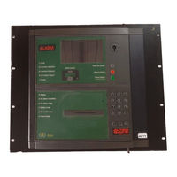
Autronica BS-320 Operator's Handbook Manual (133 pages)
Self Verify Interactive Fire Alarm System, Fire Alarm Control Panel & Operator Panel
Brand:
Autronica
| Category:
Fire Alarms
| Size: 1.19 MB
Table of Contents
Table of Contents
3
Autronica Fire and Security as Page
3
Autronica Fire and Security as Page
4
Autronica Fire and Security as Page
5
Autronica Fire and Security as Page
6
1 Introduction
7
About the Handbook
7
The Reader
7
Reference Documentation
7
Components
8
2 The Operator Panel - Overview
9
Introduction
9
Indication Devices
10
Upper Section
10
The Operator Section (Lower)
11
The Menu Display
12
Operating Buttons
13
Overview
13
Mute Panel
13
Silence Alarms
13
Front Push Buttons
14
Alphanumeric Keyboard
14
Utility Buttons
15
Internal Buzzer
15
3 Operation Mode
16
Introduction
16
Conditions in Operation Mode
17
Alarm Levels
17
Access Levels
17
How Events Are Presented in the Display
18
How to View Points in Alarm
19
How to View Detailed Zonal Information
20
Action Digits in Operation Mode
21
Resounding the Internal Buzzer
22
Resounding Fire Alarm Devices
22
Resetting the System
22
Alarm Disablement (Alarmdisable)
23
Suppressed Information
23
Disablement Sources
23
Overview
23
Point Disablements
24
Other Unit Disablements
24
Alarm Handling - a Typical Situation
25
Different Types of Detection Zones
26
Introduction
26
Immediate Action Detection Zones
26
Coincidence Action Detection Zones
27
Delayed Action Detection Zones
28
Delayed Coincidence Detection Zones
30
Solas Detection Zones
31
4 About «In the Event of
32
5 In the Event of a Fire Alarm
34
Indications in the Event of a Fire Alarm
34
Actions to be Taken in the Event of a Fire Alarm
35
6 In the Event of a Fire Alarm - with Alarm Delay
38
Indications - Fire Alarm with Alarm Delay
38
Actions to be Taken - Fire Alarm with Alarm Delay
39
7 In the Event of a Fire Warning
42
Indications in the Event of a Fire Warning
42
Actions to be Taken in the Event of a Fire Warning
43
8 In the Event of Faults
45
Indications in the Event of Faults
45
Actions to be Taken in the Event of Faults
46
9 Menu Mode
48
How to Enter Menu Mode
48
The Menu Mode Display
48
Buttons Used to Operate the Menu
49
Action Digits in Menu Mode
49
Introduction
49
Action Digits Table
49
How to Operate in Menu Mode
50
Example - How to Disable Detection Zones
50
Using the Keyboard to Enter Text into the Input Field
51
Using the Up/Down Arrows in the Selection Field
52
10 Show Status
54
Introduction
54
Show Status Menu
54
Show Status - Fire Alarms
55
Show Status - Fire Warnings
56
Show Status - Faults
57
Show Status - Disablements
58
Immediate Output Actioning
58
Show Status - Detection Zones in Test
60
Show Status - Oil & Gas Inhibited Points
61
Show Status - Activated Outputs
62
11 Disabling
64
General
64
Disable Menu
64
Indications on the Operator Panel
65
Disabling Activated / Deactivated Components
65
Disabling Detection Zones
65
Disabling Points
66
Disabling Fire Alarm Devices
66
Disabling Fire Alarm Routing Equipment
66
Disabling Outputs
66
Disabling Fault Warning Routing Equipment
67
Disabling Immediate Output Actioning
67
How to Execute Commands from the Disable Menu
68
12 Enabling
70
General
70
Enable Menu
70
Enabling Activated / Deactivated Components
71
Enabling Detection Zones
71
Enabling Points
71
Enabling Fire Alarm Devices
71
Enabling Fire Alarm Routing Equipment
72
Enabling Outputs
72
Enabling Fault Warning Routing Equipment
72
Enabling Immediate Output Actioning
72
How to Execute Commands from the Enable Menu
73
13 System Menu
75
Introduction
75
How to Set / Change Date and Time
76
How to View Current Program Version
77
How to Enter Access Level 3 / Set Password
78
Introduction
78
Enter Access Level 3
79
Leave Access Level 3
79
Set (or Change) Password
80
How to Feed Paper
81
How to Change Language
82
How to Initialize the Fire Alarm System
83
Day / Night Timers
84
Starting / Stopping Automatic Day / Night Operation from the Control Panel
84
Overriding Automatic Day / Night Operation from the Control Panel
85
14 Service Commands
86
Introduction
86
Service Menu
86
Testing
87
Testing Detection Zones
88
Testing Outputs
93
Output Control
101
Event Recording - Log Menu
103
Events
104
How to Use the Log Menu
105
Logging All Events
107
The Log Setup Menu
108
Loop Commands
113
Clear Topology
113
Disable Loop
115
Enable Loop
116
Oil & Gas Inhibit
117
Inhibit Point
117
Cancel Inhibit Point
119
15 Appendix
121
Terms and Abbreviations
121
Zonal Definitions
123
General
123
Detection Zone
123
Alarm Zone
124
Operation Zone
124
Configuration Example
125
Action Digits Table - Operation Mode
126
Menu Structure
128
16 Index
129
17 Figure List
130
18 Reader's Comments
131
Advertisement
Autronica BS-320 Installation Handbook (64 pages)
Autro Safe Self Verity Interactive Fire Alarm System, Controller
Brand:
Autronica
| Category:
Fire Alarms
| Size: 1.42 MB
Table of Contents
Table of Contents
3
1 Introduction
6
About the Handbook
6
The Reader
6
Reference Documentation
7
Environmental Requirements
8
Equipment List
8
Assembly Drawing
9
Mounting
10
Introduction
10
Location
10
Mounting Height / Space Requirement
10
Cabinet Dimensions
11
Surface Mounting
12
Removing the Front Panel
12
Mounting the Cabinet
14
C Able Inlets / Outlets
15
Cable Connections
15
Mounting the Batteries
16
Reassembling the Front Panel
16
Flush Mounting in a Wall
18
Removing the Front Panel
18
Removing the Mounting Plate
18
Flush Mounting before Construction of the Wall
19
Cut out Dimensions
20
Mounting the Cabinet
20
Reassembling the Mounting Plate
20
Cable Inlets / Outlets
21
Cable Connections
21
Mounting the Batteries
21
Reassembling the Front Panel
21
Mounting Several Panels in a 19'' Rack
21
2 Internal Cable Connections
22
Introduction
22
Before Connecting Cables
22
Location of Fuses
23
Fuses on Power Supply, BSS-103A/02
23
Fuses on Connection Module, BSF-310B
24
Shielding and Earthing
25
Introduction
25
Definitions
25
Power Supply and Battery Connections
25
Connecting 230 VAC to Power Supply BSS-103A/02
25
Connecting the Batteries to Connection Module and Power Supply
27
Connecting the Network Cables (AUTROLON)
29
External AUTROLON Cables
29
Internal AUTROLON Cable
29
Internal Cable Connections - Overview
30
Connections for Temperature Compensated Battery Charging Voltage
32
Introduction
32
Connecting the Cable to External Temperature Sensor
33
3 Installing I/O Modules
34
Introduction
34
Front View of I/O Module
35
Mounting / Removing I/O Modules
36
General
36
Mounting
36
Removing
37
Before Connecting Cables
37
Data Sheets - I/O Modules
37
Power Module, BSS-310
38
Communication Module, BSL-310
39
Loop Driver Module, BSD-310 / BSD-311
40
Output Module, Monitored, BSB-310
41
Output Module, BSJ-310
42
Input Module, Monitored, BSE-310
43
Input Module, BSE-320
44
Larger Distributed Systems
45
AUTROLON Rings with Cable Lengths >1Km
45
Limitations When Using AUTROLON Boosters
45
Overview - Cable Connections
46
Connections to the AUTROLON Booster BSL-325
47
5 Interfacing Autromaster_5000
48
General
48
Connections - Overview
49
Application with Several AUTROLON Rings
50
General
50
Application with Twisted Pair Cabling
52
Application with Fibre Optic Cabling
53
6 Guidelines for the Installation and Addressing of Loop Units
54
Introduction
54
Parameters Used During Configuration
54
Which Parameters Are Known
55
Guidelines - Known Cable Layout
55
Guidelines - Unknown Cable Layout
56
7 Service and Maintenance
57
Introduction
57
Monthly Maintenance
57
Annual Service and Maintenance
57
Autronica BS-320 Installation Handbook (64 pages)
Fire Alarm Control Panel. Controller
Brand:
Autronica
| Category:
Fire Alarms
| Size: 1.69 MB
Table of Contents
Table of Contents
3
1 Introduction
6
About the Handbook
6
The Reader
6
Reference Documentation
7
Environmental Requirements
8
Equipment List
8
Assembly Drawing
9
Mounting
10
Introduction
10
Location
10
Mounting Height / Space Requirement
10
Cabinet Dimensions
11
Surface Mounting
12
Removing the Front Panel
12
Mounting the Cabinet
14
C Able Inlets / Outlets
15
Cable Connections
15
Mounting the Batteries
16
Reassembling the Front Panel
16
Flush Mounting in a Wall
18
Removing the Front Panel
18
Removing the Mounting Plate
18
Flush Mounting before Construction of the Wall
19
Cut out Dimensions
20
Mounting the Cabinet
20
Reassembling the Mounting Plate
20
Cable Inlets / Outlets
21
Cable Connections
21
Mounting the Batteries
21
Reassembling the Front Panel
21
Mounting Several Panels in a 19'' Rack
21
2 Internal Cable Connections
22
Introduction
22
Before Connecting Cables
22
Location of Fuses
23
Fuses on Power Supply, BSS-103A/02
23
Fuses on Connection Module, BSF-310B
24
Shielding and Earthing
25
Introduction
25
Definitions
25
Power Supply and Battery Connections
25
Connecting 230 VAC to Power Supply BSS-103A/02
25
Connecting the Batteries to Connection Module and Power Supply
27
Connecting the Network Cables (AUTROLON)
29
External AUTROLON Cables
29
Internal AUTROLON Cable
29
Internal Cable Connections - Overview
30
Connections for Temperature Compensated Battery Charging Voltage
32
Introduction
32
Connecting the Cable to External Temperature Sensor
33
3 Installing I/O Modules
34
Introduction
34
Front View of I/O Module
35
Mounting / Removing I/O Modules
36
General
36
Mounting
36
Removing
37
Before Connecting Cables
37
Data Sheets - I/O Modules
37
Power Module, BSS-310
38
Communication Module, BSL-310
39
Loop Driver Module, BSD-310 / BSD-311
40
Output Module, Monitored, BSB-310
41
Output Module, BSJ-310
42
Input Module, Monitored, BSE-310
43
Input Module, BSE-320
44
Larger Distributed Systems
45
AUTROLON Rings with Cable Lengths >1Km
45
Limitations When Using AUTROLON Boosters
45
Overview - Cable Connections
46
Connections to the AUTROLON Booster BSL-325
47
5 Interfacing Autromaster_5000
48
General
48
Connections - Overview
49
Application with Several AUTROLON Rings
50
General
50
Application with Twisted Pair Cabling
52
Application with Fibre Optic Cabling
53
6 Guidelines for the Installation and Addressing of Loop Units
54
Introduction
54
Parameters Used During Configuration
54
Which Parameters Are Known
55
Guidelines - Known Cable Layout
55
Guidelines - Unknown Cable Layout
56
7 Service and Maintenance
57
Introduction
57
Monthly Maintenance
57
Annual Service and Maintenance
57
Advertisement
Advertisement
Related Products
Autronica BS-310
Autronica AutroSafe BS-330
Autronica AutroSafe BS-3
Autronica AutroSafe BS-30
Autronica BS-430
Autronica AutroSafe BS-60
Autronica AutroSafe BS-80
Autronica BS-200
Autronica AutroSafe Self Verify BSL-336
Autronica BSL-330
Autronica Categories
Security Sensors
Fire Alarms
Control Panel
Smoke Alarm
Measuring Instruments
More Autronica Manuals
Login
Sign In
OR
Sign in with Facebook
Sign in with Google
Upload manual
Upload from disk
Upload from URL