Sign In
Upload
Manuals
Brands
Automation Controls Group Manuals
Controller
301122
Automation Controls Group 301122 Manuals
Manuals and User Guides for Automation Controls Group 301122. We have
1
Automation Controls Group 301122 manual available for free PDF download: User Manual
Automation Controls Group 301122 User Manual (35 pages)
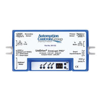
Zone Controller
Brand:
Automation Controls Group
| Category:
Controller
| Size: 3.88 MB
Table of Contents
Table of Contents
2
Introduction
6
Figure 1: the Zonelogix™ PRO System
6
Key Terms and Concepts
7
Getting Started and Installation
8
Figure 2: Zonelogix™ PRO Zone Controller Diagram
8
Zone Controller Installation
10
Figure 3: Zone Controller Mounting Tabs
10
Zone Installation
11
Figure 4: the Zonelogix™ PRO System
11
Figure 5: Unidrive Motor Stopping Distance
12
Configuration DIP Switches
13
Figure 6: Default DIP Switch and Smart I/O
13
24VDC Power Connection
14
Zone-To-Zone Cable Connection
14
Figure 7: Zone-To-Zone Communication Connections
14
Table 1: DC Power Input Connection
14
PNP Photoeye Sensor Connection
15
Table 2: PNP Sensor Connection Header
15
Smart I/O Connections
16
Basic Mode Functions
16
Table 3: Smart I/O Pin Definitions for the EOB Zone Controller
16
Table 4: Smart I/O Pin Definitions for the Standard Zone Controller
16
Advanced Mode Functions
17
Table 5: Smart I/O Pin Definitions for the Master Zone Controller in Basic Mode
17
Table 6: Operating Modes for Smart I/O Pins 1 & 2 on the Master Zone Controller in Basic Mode
17
Table 7: Speed Input Analog Control
17
LED Feedback Indicators
18
Figure 8: LED Definitions
18
System Schematic and Installation Summary
19
Figure 9: Schematic Diagram of Zonelogix™ PRO System
19
Basic Mode System Operation & Configuration
20
System Start up - Apply 24 VDC Power
20
Zone Discovery
20
Lost Package Detection
20
Sleep Timer
20
Figure 10: Standard Zone Controller Leds in Normal Operation
20
EOB Zone Configuration
21
Controlling Object Entry - Forward (Normal) Flow Direction
21
Master Zone Configuration
21
Controlling Object Exit
21
Changing Operational Modes
21
Controlling Branch Direction
21
Controlling Branch Speed
21
Basic Mode Parameters
21
Table 8: Parameters in Basic Mode
22
Zone Controller Updates
23
Advanced Mode System Configuration
24
Motor Performance
25
Figure 11: Motor Performance Curves
25
Breakout Module
27
Handshaking Functionality
27
Figure 12: Breakout Module (Product 300332)
27
Figure 13: Handshaking Signals Showing Forward and Reverse Flow Request / Permission Signals
28
Figure 14: Handshaking Signals Showing both Forward / Reverse Request / Permission Signals
28
Figure 15: Internal Diagram of the Breakout Module
28
Breakout Module Example: Connect Two Branches
29
Breakout Module Example: Connect Two Branches with Branch Monitor
29
Figure 16: Breakout Module Connecting Two Branches
29
Figure 17: Breakout Module Connecting Two Branches and Branch Monitor
29
Breakout Module Example: Transfer Application
30
Figure 18: Breakout Modules in a Transfer Application
30
Diagnostics & Troubleshooting
31
Feedback Leds
31
Fuse LED (Red)
31
Figure 19: Feedback Leds
31
Fault LED (Red)
32
Motor LED (Amber)
32
Table 9: Fault LED
32
Table 10: Motor Current LED
32
Firmware Version Display
33
Additional Assistance
33
Document Revision History
33
Figure 20: Firmware Version Display Example
33
Appendix A: Operating Modes
34
Singulate (ZPA)
34
A.2. Slug
34
Figure 21: Singulate (Singulate Mode)
34
Figure 22: Slug (Slug Mode)
34
A.3. Zip
35
A.4. Zone Hold
35
Figure 23: ZIP (Operating Mode)
35
Figure 24: Zone Hold (Singulate, ZIP, and Slug Modes)
35
Advertisement
Advertisement
Related Products
Automation Controls Group UniDrive ZoneLogix PRO
Automation Controls Group Categories
Control Unit
Controller
More Automation Controls Group Manuals
Login
Sign In
OR
Sign in with Facebook
Sign in with Google
Upload manual
Upload from disk
Upload from URL