Sign In
Upload
Manuals
Brands
Astronics Manuals
Pulse Generator
PXIe-1209
Astronics PXIe-1209 Manuals
Manuals and User Guides for Astronics PXIe-1209. We have
1
Astronics PXIe-1209 manual available for free PDF download: User Manual
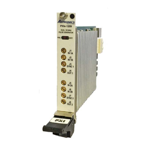
Astronics PXIe-1209 User Manual (60 pages)
Dual 100 MHz Pulse Generator
Brand:
Astronics
| Category:
Pulse Generator
| Size: 2.01 MB
Table of Contents
Table of Contents
5
Chapter 1
13
Overview and Features
13
Functional Description
14
Figure 1-1, Pxie-1209
14
Direct Digital Synthesizer (DDS)
15
Figure 1-2, Pxie-1209 Functional Block Diagram
15
Microcontroller
15
Pulse and Timing Control Logic
15
Pxie Interface
15
Front Panel Input Signals
16
Backplane Trigger Signals
16
Operational Modes
16
Pin Drivers
16
Vcxo
16
Figure 1-3, Pulse Terms and Relationships
17
Frequency (Pulse Repetition Rate)
17
Pulse Delay and Double Pulse Spacing
17
Pulse Width
17
Run Modes
17
Single Pulse or Double Pulse
17
External Gate
18
External Reference Clock
18
External Trigger
18
Pulse Output
18
Sync out
18
Hardware Configuration
18
Front Panel Signals a & B Input Impedance
19
Sync out Level
19
Figure 1-4, Pxie-1209 Hardware Configuration Switches
19
Mode
20
Input/Output Signals
20
Figure 1-5, Front Panel
20
Chapter 2
23
Specifications
23
Maximum Ratings Per Module
23
AC Characteristics Per Channel
23
Mechanical
25
Bus Compliance
25
Environmental
25
Mechanical
26
Chapter 3
27
Installation
27
Unpacking and Inspection
27
Installing the Module into a Pxie Chassis
27
Software Installation
27
Installing the VISA Driver
27
Installing the PXI Device Driver
28
Installing the Labview Instrument Driver
28
Installing the Labwindows/CVI Instrument Driver
29
Chapter 4
31
Operation
31
Programming
31
Writing Register Values
31
Pulse Programming
31
Pulse Delay
31
Sync out
32
Frequency (Internal Pulse Repetition Rate)
32
Single Pulse Vs. Double Pulse
32
Single, Continuous, and Burst Modes
33
Follow Trigger Mode
33
Pulse Gating
33
Calibration
33
Reference Disciplining
34
Interrupts
34
Chapter 5
35
Software Operation
35
Using the Soft Front Panel
35
Starting the Soft Front Panel
35
Figure 5-1, Starting Soft Front Panel
35
Figure 5-2, Ri1209E Main Panel
36
Figure 5-3, Instrument Menu
37
Figure 5-4, Configure Menu
37
Figure 5-5, Pulse Output Configuration Window
38
Figure 5-6, Sync Output Configuration Window
38
Figure 5-7, Gate & Trigger Configuration Window
39
Figure 5-8, M-Triggers Routing Window
39
Figure 5-9, Gate and Trigger Subwindow
41
Figure 5-10, External Reference Configuration Window
42
Using the Labwindows / CVI Driver
43
Figure 5-11, Front Panel Inputs Configuration Window
43
Using the Labview Driver
45
Chapter 6
49
Identification and Configuration Registers
49
I/O Registers
49
Control Status
50
Interrupt Control
51
Trigger/Gate Control
52
Version Info
52
DDS Frequency - Low
53
DDS Frequency - High
53
Frequency Divider - Low
53
Frequency Divider - High
53
Pulse Width - Low
54
Pulse Width - MID
54
Pulse Width - High
54
Pulse Delay - Low
55
Pulse Delay - MID
55
Pulse Delay - High
55
Double Pulse Spacing - Low
56
Double Pulse Spacing - MID
56
Double Pulse Spacing - High
56
Burst Count - Low
57
Burst Count - High
57
Output Amplitude - Low Level
57
Slew Rate
58
Input Threshold Level
58
Calibration Control
58
Reference Count - Low
59
Reference Count - High
59
Advertisement
Advertisement
Related Products
Astronics PXIe-3352
Astronics Categories
Control Unit
Measuring Instruments
Recording Equipment
Scanner
Computer Hardware
More Astronics Manuals
Login
Sign In
OR
Sign in with Facebook
Sign in with Google
Upload manual
Upload from disk
Upload from URL