Sign In
Upload
Manuals
Brands
Aspen Avionics Manuals
Avionics Display
EFD1000 E5
Aspen Avionics EFD1000 E5 Manuals
Manuals and User Guides for Aspen Avionics EFD1000 E5. We have
1
Aspen Avionics EFD1000 E5 manual available for free PDF download: Installation Manual
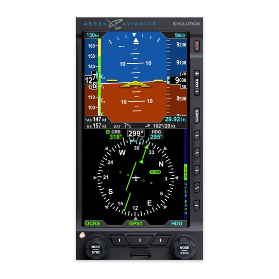
Aspen Avionics EFD1000 E5 Installation Manual (226 pages)
Dual Electronic Flight Instrument
Brand:
Aspen Avionics
| Category:
Avionics Display
| Size: 3.3 MB
Table of Contents
Table of Contents
5
List of Tables
12
List of Figures
13
List of Definitions, Acronyms, Abbreviations
16
Introduction
17
Part Numbers
17
Latest Approved Software Versions
17
Table 1-1: Part Numbers
17
Table 1-2: Latest Approved Software Version
17
Aml-Stc Document List
18
Installation Kit Contents
18
Table 1-3: AML-STC Additional Document List
18
Table 1-4: 903-00001-( ) EFD1000 EFD Install Kit
18
Table 1-5: 903-00007-001 EFD Recess Mount Kit (Optional)
18
Table 1-6: 903-00002-( ) RSM Install Kits
18
1.3 Optional LRU Install Kits
19
Table 1-7: 903-00003-001 ACU Install Kit
19
Table 1-8: 903-00003-002 ACU2 Install Kit
19
Table 1-9: 903-00011-( ) EA100 Install Kits
19
Accessories Required but Not Supplied - Efd1000 E5
20
Optional Accessories Not Supplied - Efd1000 E5
20
Optional Accessories Required but Not Supplied - Ea100
20
Table 1-10: EFD1000 E5 Accessories Required but Not Supplied
20
Table 1-11: E5 Optional Accessories Not Supplied
20
Table 1-12: EA100 Optional Accessories Required but Not Supplied
20
Special Tools Required
21
Vendor Information
21
Warranty Registration
21
Regulatory Compliance
21
Technical Standard Order
21
Pma Approval
21
Table 1-13: Special Tools
21
Software Certification
22
Environmental Compliance
22
Installation Approval
22
Field Replaceable Parts
22
Reserved
22
Equipment Specifications and Limitations
23
Efd1000 E5
23
General Specifications
23
Operational Specifications
23
I/O Specifications
23
Certification Specifications
23
Efd1000 E5 Outline Drawing
24
Design Eye Viewing Envelope
24
Figure 2-1: EFD1000 E5 Outline Drawing (Inches)
24
Remote Sensor Module (Rsm)
25
General Specifications
25
Operational Specifications
25
I/O Specifications
25
Certification Specifications
25
Outline Drawing
26
Configuration Module (CM)
26
General Specifications
26
Figure 2-2: RSM Outline Drawing (Inches)
26
Operational Specifications
27
I/O Specifications
27
Certification Specifications
27
Outline Drawing
27
Figure 2-3: Configuration Module Outline Drawing (Inches)
27
Analog Converter Unit (Acu)
28
General Specifications
28
Operational Specifications
28
I/O Specifications
28
Certification Specifications
28
Outline Drawing
29
Analog Converter Unit 2
29
General Specifications
29
Operational Specifications
29
I/O Specifications
29
Figure 2-4: ACU Outline Drawing (Inches)
29
Certification Specifications
30
Outline Drawing
30
Figure 2-5: ACU2 Outline Drawing (Inches)
30
System Description
31
Efd1000 E5 Dual Electronic Flight Instrument (Efi) System
31
Efd1000 E5 Flight Display (Efd)
31
Remote Sensor Module (Rsm)
32
Configuration Module (CM)
32
Analog Converter Unit (Acu)
32
Analog Converter Unit 2 (Acu2)
32
System Architecture
33
Figure 3-1: EFD1000 E5 System Architecture
33
Stc Specific Requirements and Limitations
35
Efd1000 E5 System Limitations
35
EA100 Installation Limitations (EA100 Is Optional)
35
Authorized Configurations
35
Figure 4-1: EFD1000 E5 Authorized IFR Configuration
36
General Standby Instrument Requirements for Ifr-Capable Airplanes
38
Pneumatic Attitude (Existing)
38
Electric Attitude (Existing)
38
Existing Attitude Positioning (if Keeping)
38
Figure 4-2: Flight Director/Backup Nav/Placard Placement
39
Airspeed and Altimeter
40
Back up Nav Indicator
40
Placards
40
4.5 Special Consideration for Airplanes Limited to VFR
41
Pre-Modification Planning
42
Pre-Modification Checklist
42
Table 5-1: Pre-Modification Checklist
42
Directional Gyro/ HSI
43
Aircraft Power Requirements
43
Equipment Power Requirements
43
Reserved
43
Cessna 190/195 Special Consideration
44
Reserved
44
Conventional Landing Gear "Tail Dragger" Aircraft
44
Optional Interfaces
45
Autopilot
45
5.4.1.1 EA100 Adapter
45
Gps Navigator Compatibility
46
Gpss
46
Gps/ Nav Switching
46
Table 5-2: GPS Compatibility
46
Heading Output
47
Air Data Outputs
47
5.4.6.1 EFD1000 E5 as Encoding Altitude Source
47
Table 5-3: Heading Sources
47
Table 5-4: Air Data Sources
47
Flush or Recess Mounting the Efd
48
Mechanical Installation
50
Unpacking and Inspecting Equipment
50
Equipment Location Documentation
50
Log Book Entry
50
Weight and Balance
50
Mounting Limitations
50
Table 6-1: Component Weights
50
Efd1000 E5 Mounting Limitations (Efd)
51
Rsm Mounting Limitations
51
Equipment Bonding
51
Cooling
52
Efd Installation
52
Efd Mounting Location
52
Surface Mounting the Efd as Per Figure 6-2
52
Figure 6-1: EFD Mounting Location
52
Figure 6-2: EFD and Bracket Installation
53
Recess Mounting the Efd as Per Figure 6-4
54
6.8.3.1 Recess Mount Modification Procedure
54
Table 6-2: Parts Required to Recess Mount each EFD
54
Figure 6-3: Single Display Recess Mount Cutout (Inches)
55
Figure 6-4: Single Display Recess Mount Bracket Installation
56
Table 6-3: Static Load Table
57
Figure 6-5: Ground Strap Attachment Points
57
Figure 6-6: Recess Mounting Bracket Dimensions (Inches)
58
Figure 6-7: EFD Mounting Bracket (Inches)
58
Efd Bonding Strap
59
Pitot and Static Connections
59
Figure 6-8: EFD Bonding Strap Connection
59
Figure 6-9: Pitot & Static Quick Connector
59
Quick Connector Installation
60
Leak Check Requirements
60
Figure 6-10: Pitot & Static Line Connections
60
Rsm Installation
61
Rsm Internal Mounting
61
Rsm Inverted or Bottom Mounting
61
Rsm External Top Mounting
61
Figure 6-11: RSM-External Mounting Locations (Top/Side View) - All Aircraft Types
63
Figure 6-12: RSM Internal Mounting Locations - Composite/Fabric Aircraft
64
Proposed Rsm Location Check
65
Figure 6-13: RSM-003 External Mounting Locations (Bottom View)
65
Pressurized Aircraft
67
RSM Mounting on Non-Metal or Damage-Tolerant Design Aircraft
68
Rsm Mounting Angles
68
6.9.7.1 Longitudinal Axis
68
6.9.7.2 Pitch Axis
68
Figure 6-14: RSM Top View Longitudinal Alignment
68
6.9.7.3 Roll Axis
69
Figure 6-15: RSM Fore or Aft Max Tilt
69
Figure 6-16: RSM Fore or Aft Max Tilt (Shim Installed)
69
Figure 6-17: RSM Side to Side Max Tilt
69
Figure 6-18: RSM Side to Side Max Tilt (Shim Installed)
69
Rsm External Mount - Aluminum Skin
70
6.9.8.1 RSM Doubler Fabrication
70
Figure 6-19: RSM Doubler P/N 503-00015-001
70
Figure 6-20: Masking of Doubler
71
Rsm Internal Mount
72
Rsm Installation
72
Table 6-4: RSM Mounting Hardware
72
Figure 6-21: Doubler Installation
72
RSM Shim Fabrication (if Necessary)
73
Figure 6-22: RSM Mounting
73
Figure 6-23: Example Shim Top View
73
Figure 6-24: Example Shim Side View
73
Acu/Acu2 Installation
74
Figure 6-25: Masking of Shim for Priming
74
Acu/Acu2 Mounting
75
Figure 6-26: ACU/ACU2 Mount to Flat Metal Shelf
75
Figure 6-27: ACU Dimensions (Inches)
76
Figure 6-28: ACU2 Dimensions (Inches)
77
Configuration Module Installation
78
Figure 6-29: Configuration Module Dimensions (Inches)
78
Figure 6-30: Configuration Module Tie Wrapped to Harness
78
Electrical Installation
80
Electrical Load Analysis
80
Efd1000 E5
80
ACU or ACU2 (Optional)
80
Miscellaneous Wiring
80
Table 7-1: Current Draw
80
Hirf/Lightning Requirements
81
Efd to Gps/Vloc/Acu Wiring
81
Figure 7-1: EFD Back Shell Grounds
81
Rsm Wiring
82
7.2.6.1 Assembly Using Aspen Prefabricated 35Ft and Optional 50Ft Cables
82
7.2.6.2 Assembly Using M27500-A24SD7T23 Cable
82
Efd End
83
Configuration Module Wiring
83
Figure 7-2: RSM Connector Assembly
83
Figure 7-3: EFD Back Shell Grounds/Rsm
83
Acu Wiring
84
Back U Pnav Indicator Wiring
84
Autopilot Wiring
84
Backup Instrument Wiring and Cable Bundle
84
Electrical Connections
86
Efd Electrical Specifications
86
Power Input
86
RS-232 GPS Input
86
Adc Output
86
Arinc 429 Gps Inputs
86
Table 8-1: RS-232 ADC Outputs
86
Arinc 429 Vloc Input
87
Arinc 429 Output
87
Table 8-2: EFD A429 GPS Input
87
Table 8-3: EFD A429 VLOC Input
87
ACU Electrical Specifications (910-00004 All Dash Numbers)
88
Power Input
88
Reserved
88
Vloc Receiver
88
8.2.3.1 NAV Composite Input
88
8.2.3.2 ILS Energize Discrete Input
88
8.2.3.3 Glide Slope Deviation Input
88
Table 8-4: EFD1000 E5 A429 GPS Output
88
8.2.3.4 Glide Slope Flag Input
89
Gps Receiver
89
8.2.4.1 OBS Sine, Cosine, Rotor
89
8.2.4.2 TO/ from FLAG Input
89
8.2.4.3 LEFT/ RIGHT Input
89
8.2.4.4 Lateral Flag Input
89
8.2.4.5 Vertical Deviation Input
89
8.2.4.6 Vertical Deviation Flag Input
89
8.2.4.7 OBS/ LEG (HOLD) Input
89
8.2.4.8 APPR Active Input
90
8.2.4.9 FCS-LOC Engage Input
90
Autopilot
90
8.2.5.1 Lateral Deviation Output
90
8.2.5.2 Lateral Flag Output
90
8.2.5.3 Vertical Deviation Output
90
8.2.5.4 Vertical Flag Output
90
8.2.5.5 ILS Energize Output
90
8.2.5.6 Volt Reference Output
91
8.2.5.7 KI-525A Heading and Course Datum Output
91
8.2.5.8 NSD-360 Heading and Course Datum Output
91
Table 8-5: KI525A Emulation Specifications
91
8.2.5.9 PN-101 Heading and Course Datum Output
92
Heading Valid Output
92
Table 8-6: NSD360A Emulation Specifications
92
Table 8-7: PN101 Emulation Specifications
92
Gps Selected Output
93
Arinc 429 Output
93
Acu2 Electrical Specifications (910-00004-10 X Only )
93
Heading Synchro out
93
Table 8-8: ACU A429 Output
93
+/- 15Vdc Power Output
94
Glideslope Flag (Narco)
94
Arinc 429 Output
94
Efd Pin out
94
Table 8-9: ACU2 ARINC 429 Output
94
Table 8-10: EFD Pin out
95
Figure 8-1: EFD Connector (as Viewed from Rear of Unit)
95
Rsm Pin out
96
Configuration Module Pin out
96
Table 8-11: RSM Pin out
96
Table 8-12: Configuration Module Pin out
96
Figure 8-2: RSM Mating Connector -Install Side
96
Figure 8-3: Configuration Module Connector (Install Side)
96
Acu/Acu2 Pin out
97
Table 8-13: ACU J1 Pin out
97
Figure 8-4: ACU J1 Connector (as Viewed from Front of Unit)
97
Table 8-14: ACU J2 Pin out
98
Figure 8-5: ACU J2 Connector (as Viewed from Front of Unit)
98
Table 8-15: ACU J3 Pin out
99
Figure 8-6: ACU J3 Connector (as Viewed from Front of Unit)
99
Figure 8-7: ACU2 J4 Connector (ACU2 Only)
101
Installation Wiring Diagrams
102
List of Wiring Diagrams - Efd1000 E5
102
Optional Interfaces - Acu and Acu2
103
Table 9-1: E5 Wiring Diagrams
103
Table 9-2: Optional ACU/ACU2 Interfaces
103
Figure 9-1: EFD1000 E5 Main Connections
104
Figure 9-2: ACU/ACU2 Input Power
105
Figure 9-3: Reserved
105
Figure 9-4: VFR Only no GPS Input Configurations
105
Figure 9-5: ARINC 429 GPS Without ACU
105
Figure 9-22: Reserved
105
Figure 9-6: GNAV Without ACU ("Tracker" or no Autopilot)
106
Figure 9-7: GNAV with ACU (Autopilot)
107
Figure 9-8: Reserved
107
Figure 9-9: Reserved
107
Figure 9-23: Reserved
107
Figure 9-10: ARINC 429 GPS with ACU (Analog Nav And/Or Autopilot)
108
Figure 9-11: RS-232 GPS with ACU (Analog Nav And/Or Autopilot)
109
Figure 9-12: KLN89B & KLN94 RS-232 and Analog to ACU Interface
110
Figure 9-13: KLN-90/A/B RS-232 and Analog to ACU Interface
111
Figure 9-14: GX-50/60 & GX-55/65 RS-232 and Analog to ACU Interface
112
Figure 9-15: Analog NAV Interface
113
Figure 9-15A: Narco and Cessna ARC Navigation Radios
114
Figure 9-16: KI525A Emulation (Bendix/King Autopilot to ACU)
115
Figure 9-17: S-TEC Autopilot to ACU Interface
116
Figure 9-18: Century Autopilot to ACU Interface (Minus HDG/CRS Datum)
117
Figure 9-18A: NSD360A Emulation (Century 21/31/41/2000/4000)
117
Figure 9-18B: NSD360A Emulation Century 1C388/M, 1C388C/MC Radio Couplers
118
Figure 9-18C: NSD360A Emulation Century 1C388-2/-3 Radio Couplers
119
Figure 9-18D: NSD-360A Emulation Century IV (DC Version)
120
Figure 9-19: Cessna ARC 300B/400B/800B Autopilot to ACU Interface
121
Figure 9-19A: Cessna Navomatic 300/400/800 IFCS to ACU Interface
122
Figure 9-19B: NAVOMATIC 400/400A Autopilot to ACU Interface
123
Figure 9-19C: Cessna ARC 300A AC & DC Version to ACU Interface
124
Figure 9-19D: Cessna 300 Navomatic to ACU Interface
125
Figure 9-20: Bendix FCS-810 Autopilot to ACU
126
Figure 9-21: Reserved
127
Figure 9-24: Back-Up NAV Indicator (Internal Converter)
127
Figure 9-25: Back-Up NAV Indicator (OBS Resolver)
128
Figure 9-26: Back-Up NAV/GPS Indicator (GNS-430/530)
129
Figure 9-27: Non-Aspen Equipment Configuration Notes
130
Figure 9-28A: Digital Heading/Adc Outputs
131
Figure 9-28B: ARINC 407 Synchro Output (ACU2 Only)
132
10 Configuration and Equipment Checkout
134
Wiring Checks
134
Bonding Check - 14Cfr
134
Onding Heck - 14Cfr 23.867( )
134
Initial System Turn on
134
System Configuration
135
Main Menu Access
135
Menu Navigation
135
Edit Mode
135
Main Menu Configuration
135
Installation Menu - Unit Configuration
135
Figure 10-1: Installation Menu Access
136
Figure 10-2: Installation Menu Warning
136
Efd1000 E5 Installation Menu Configuration
138
Installation Menu Configuration - Efd1000 E5
138
Installation Menu Page - Ias Config a
138
Table 10-1 MOL Type and Parameter Descriptions
139
Installation Menu Page - Ias Config B
140
Installation Menu Page - Ias Config C
140
Installation Menu Page - Ias Config D
140
Installation Menu Page - Ias Config E
140
Installation Menu Page - Ias Config F
141
Installation Menu Page - Ias Config G
141
Installation Menu Page - Nav Setup a
142
Installation Menu Page - Nav Setup B
142
Installation Menu Page - Nav Setup C
143
Installation Menu Page - Rs-232 Config a
143
Installation Menu Page - Rs-232 Config B
144
Installation Menu Page - Rs-232 Config C
144
Installation Menu Page - Acu Config a
144
Installation Menu Page - Acu Config B
145
Installation Menu Page - Misc Config a
145
Installation Menu Page - Misc Config B
145
Installation Menu Page - Misc Config C
146
Installation Menu Page - Misc Config D
146
Installation Menu Page - Rsm Calibration
146
Installation Menu Page - Accel Bias Cal
148
Installation Menu Page - Wx-500
148
Installation Menu Page - Dfc A/P Config
148
Installation Menu Page - Aoa Config
148
Installation Menu Page - Network Page
148
Installation Menu Page - Diagnostics
149
Configuration Definitions
149
Ias Configurations
149
Figure 10-3: Notional Diagnostics Page
149
Panel Tilt Pitch Adj
150
Figure 10-4: Illustration of Aircraft 2º Nose High
151
Figure 10-5: Illustration of Zero Degree Pitch Adjustment
151
Panel Roll Adj
152
Attitude Ref Symbol Adj
152
Nav Setup Configuration
152
Gps/Nav#1 (ID#1)
152
Composite Phase (Vor1, Vor2)
152
Acu Configuration
152
Acu Hsi Type
152
Figure 10-6: GPS/NAV Example
152
Acu Datum
153
Exiting / Saving Data
153
Rsm Calibration
153
Calibration Overview
153
Figure 10-7: HSI Type Example
153
Second Phase Rsm Location Evaluation
154
Table 10-2: Vertical Component Evaluation Table
154
Figure 10-8: Nt Example
155
Figure 10-9: EFD1000 Diagnostic Page Magnetometer Row Example
155
Conventional Gear Rsm Calibration Procedure
156
Figure 10-10: RSM Calibration Graphic
157
Rsm Calibration Procedure
158
Figure 10-11: RSM Calibration Page
158
Figure 10-12: Calibration in Process
159
Figure 10-13: Aircraft Turning
159
Figure 10-14: Accept/Reject Results
159
Heading Offset Adjustment
160
Figure 10-15: Results Accepted
160
Figure 10-16: Results Rejected
160
Figure 10-17: Calibration Heading before Adjustment
160
Heading Accuracy Test
161
Heading Interference Test
161
Figure 10-18: Calibrated Heading after Adjustment
161
Ground Test Procedure
162
Indicated Airspeed Display
162
Altitude Display
163
System Leak Test
163
Ahrs Sensor Test
163
GPS1 Sensor Test (Labeled as GPS1)
163
All Gps Interfaces
163
Analog Gps Interfaces
163
NAV Receiver Sensor Test (Label as VLOC1)
164
Backup Navigation Indicator
164
Autopilot Sensor Test
164
Ancillary Equipment Heading Check
165
Ancillary Equipment Air Data Check
165
Internal Battery Tests
165
Tapes Configuration Check
165
Emi Test
166
Flight Control Interference Check
169
Obs Mode Check
169
Ea100 Adapter Testing
170
11 Post Installation Flight Check
171
Attitude Display Flight Checks
171
Heading Card Flight Checks
171
Ils Flight Checks
171
Autopilot Flight Checks (if Installed)
172
Document Operational Check
172
12 Operating Instructions
173
Pilot Controls
173
Overview
173
Power Control
173
Environmental Qualification Forms
175
Table 13-1: EFD1000 E5 Environmental Qualification Form
175
Table 13-2: RSM Environmental Qualification Form
176
Table 13-3: ACU Environmental Qualification Form
177
Appendix A : Troubleshooting
179
Appendix B : Installation Final Check Sheet
185
Appendix D : Component Maintenance Manual (CMM)
193
Appendix C : Sample of Afms Section 1.2 (Installed Equipment Configuration Matrix)
195
Appendix E : Ea100 Adapter
195
E1 General Limitations
196
E2 Ea100 Specifications
197
Figure E1: EA100 Outline Drawing (Inches) and Center of Gravity
198
Figure E2: EA100 Block Diagram (Bendix King Autopilots)
198
Figure E3: EA100 Block Diagram (Century Autopilots)
198
E3 Outline Drawing
198
E4 Ea100 System Architecture
198
E5 Ea100 Installation
199
E5.1 Equipment Location Documentation
199
E5.2 Weight and Balance
199
E5.3 Mechanical Installation
199
Figure E4: EA100 Mounting
200
E5.4 Electrical Installation
201
Figure E5: A/P AHRS FAIL Annunciator Location
202
Figure E6: MS25041-4 Dimmable "Catseye
203
E5.5 Fabrication of Tr1 or Tr2 Transformer Isolation Box (Century Autopilots Only)203
203
E5.6 Electrical Connection
204
E5.7 Wiring Diagrams
205
Figure E8: EA100 Main Wiring Connections(King and Century)
206
Figure E9: EA100 to KAP100/KAP150/KFC150 Attitude Source W/Disc
207
Figure E10: EA100 to KAP/KFC200 Attitude Source W/Disc
208
Figure E11: EA100 to KFC225 Attitude Source W/Disc
209
Figure E12: EA100 to KFC250 (with KA141) Attitude Source W/Disc
210
Figure E13: EA100 to KFC250 (Without KA141) Attitude Source W/Disc
211
Figure E14: Reserved
211
Figure E15: EA100 to Century IIB Attitude Source W/Disc
212
Figure E16: EA100 to Century III Attitude Source W/Disc
213
Figure E17: EA100 to Century IV Attitude Source W/Disc
214
Figure E18: EA100 to Century 21 Attitude Source W/Disc
215
Figure E19: EA100 to Century 31 Attitude Source W/Disc
216
Figure E20: EA100 to Century 41 Attitude Source W/Disc
217
Figure E21: EA100 to Century 2000 Attitude Source W/Disc
218
Figure E22: EA100 to Century 4000 Attitude Source W/Disc
219
E5.8 Configuration
220
E5.9 Ea100 Ground Test Procedure
220
E5.9 Autopilot Gyro Alignment
222
E5.10 Ground Emi Test
222
Advertisement
Advertisement
Related Products
Aspen Avionics EFD1000H PFD
Aspen Avionics Evolution Backup Display EFD1000C3
Aspen Avionics EFD1000 Dual EFI
Aspen Avionics Evolution Backup Display EFD1000H
Aspen Avionics Evolution Backup Display EFD500
Aspen Avionics Evolution Backup Display EFD500H
Aspen Avionics Evolution E5 Dual EFI
Aspen Avionics Evolution Backup Display Basic
Aspen Avionics Evolution EFD1000 PFD
Aspen Avionics Evolution EFD 1000 C3 Pro PFD
Aspen Avionics Categories
Avionics Display
Monitor
Autopilot System
GPS
More Aspen Avionics Manuals
Login
Sign In
OR
Sign in with Facebook
Sign in with Google
Upload manual
Upload from disk
Upload from URL