Sign In
Upload
Manuals
Brands
Ametek Manuals
Measuring Instruments
LAND Genesis WDG-1210
Ametek LAND Genesis WDG-1210 Manuals
Manuals and User Guides for Ametek LAND Genesis WDG-1210. We have
1
Ametek LAND Genesis WDG-1210 manual available for free PDF download: User Manual
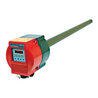
Ametek LAND Genesis WDG-1210 User Manual (97 pages)
Insitu Oxygen Probes
Brand:
Ametek
| Category:
Measuring Instruments
| Size: 7.56 MB
Table of Contents
Health and Safety Information
2
Signs and Symbols Used on Equipment and Documentation
2
Table of Contents
5
1 Overview
7
System Features
7
Key Features and Benefits
7
Sensor
8
The Oxygen Measuring Cell
8
Three Simple Systems in the Analyzer
9
Zirconium Oxide Cell Principle of Operation
9
Problems to Avoid
10
Technical Support
10
2 Specifications
11
WDG 1200/1210/Insitu Probe
11
3 Installation and Start-Up
15
Unpacking
15
Mechanical Installation
16
Location
16
Unpacking the Shipping Protection
17
Fitting a Filter or Shield to the Probe
18
Filter Installation
18
Mounting the Sensor
19
WDG-1200 Insitu Sensor Mounting
19
WDG-1210 Insitu Sensor Mounting
19
Mounting the Controller
20
Model 1210 Insitu Oxygen Probe System Key Components
20
Mounting Guidelines
21
Selecting the Measurement Location
21
Installing the Controller
22
Mounting the Control Unit
22
Control Unit Dimensional Information
22
Mounting Details
22
Calibration Setup
23
Calibration Inlet
23
Required Calibration Gases and Tubing
23
Calibration Gas Port WDG-1200 Insitu
23
Electrical Connections
24
Remote Calibration Unit
24
Optional Signal Connections
25
Plug Plate Connector Designation - WDG-1200 Insitu
25
Plug Plate Connector Designation - WDG-1210 Insitu
26
System Cables
26
Recommendations for Laying Cable
26
Cable Preparation
27
Setting the Supply Voltage in the System Units
27
Grounding
27
Cable Recommendations - WDG-1200 Insitu
28
Cable Recommendations - WDG-1210 Insitu
29
Pin Designations - 1200/1210 Insitu
29
Probe Connections - WDG-1210 Insitu Only
31
Probe Electrical Connections
31
Assembly of Connector Plugs
33
Crimped Connector Assembly Procedure
33
Mains Power Supply Plug
35
Mains Connector Assembly Procedure
35
Fitting of Plug Connectors
35
Pre-Operational Checks - Final Checks
36
4 User Interface and Calibration
37
Control Panel
37
Abbreviations Used on the Control Panel
38
Using the Probe for the First Time
39
Warm up Procedure
39
System Leds
39
Operational Structure
40
Password
40
Maintenance Relay Option
40
Probe Display Settings
41
Operational Structure Diagram
41
Calibration Screens
42
Calibration Menu
42
Span Gas Concentration
44
Zero Gas Concentration
44
Calibration Time Interval
44
Time to Next Calibration
44
Calibration Settling Time
45
Automatic Calibration
45
Zero Calibrati/On
45
Manual Span Calibration
45
Alarm Screen
46
Alarm Menu
46
Alarm Setting
46
Analog Outputs Screens
47
Analog Outputs Menu
47
Zero Setting
48
Analog Outputs Span Setting
48
Analog Outputs Damping Setting
48
Base Setting
48
Diagnostics Screens
49
Diagnostics Menu
49
Fault List
50
Cell EMF
50
Cell Temperature
50
Cold Junction Temperature
50
System Configuration Screens
51
System Configuration Menu
51
Probe Type
52
Baud Setting
52
Negative Values
52
Probe Address
52
Output Setup
53
System Outputs
53
Analog Output Settings
55
Zero Reading
55
Span Reading
55
Damping
55
Track Setting
56
Modbus Interface
57
Serial Data Bus Configuration
57
Slave Address and Floating Point Format
57
Register Numbers
58
Modbus RS485 Interface
59
Full Register List
60
Zero and Span Calibration
62
Access to Calibration Menu from Menu Spine
62
Oxygen Concentration
62
Maintenance Relay
62
Configuration
64
Configuration Sub-Menu
64
Span Calibration Gas Concentration
64
Settling Time
64
Automatic Calibration Sub-Menu
65
Remote Triggering
65
Manual Calibration
66
Zero Calibration
66
Zero Calibration Reading
66
Span Calibration
67
Span Calibration Reading
67
5 Maintenance and Troubleshooting
69
Identifying Faults
69
Fault Identification Numbers
71
Fault Identification Table
71
Fault Description
72
Bench Testing
75
In-Situ Probe Testing and Checking
76
Thermocouple V. Ambient Temperature for a Probe at 750°C/1382°F
78
Routine Maintenance Schedule
80
6 Service and Parts
81
Inner Probe Assembly Removal
82
Process under Pressure
83
Сell Replacement
84
Removing the Cell
84
Cell Assembly
84
Cell and Heater Replacement
85
Fitting the New Cell
86
Cell Clip with Attached Cell Leads
88
Cell and Retainer Clip Placement
89
Heater/Thermocouple Replacement
90
Removing Heater
90
Replacing Heater
90
Spare Parts
91
Appendix - Drawings and Custom Instructions
93
Mounting and Dimension Probe
94
Advertisement
Advertisement
Related Products
Ametek LAND Genesis WDG-1200
Ametek WDG-V UOP
Ametek WDG-V
Ametek WDG-VC
Ametek WDG-VCM
Ametek WDG-VM
Ametek WDG-V HP Series
Ametek WDG-V/S Series
Ametek WDG-V HP
Ametek WDG-VC HP
Ametek Categories
Measuring Instruments
Test Equipment
Power Supply
Controller
Switch
More Ametek Manuals
Login
Sign In
OR
Sign in with Facebook
Sign in with Google
Upload manual
Upload from disk
Upload from URL