Sign In
Upload
Manuals
Brands
Amazone Manuals
Farm Equipment
Cirrus 03
Amazone Cirrus 03 Manuals
Manuals and User Guides for Amazone Cirrus 03. We have
2
Amazone Cirrus 03 manuals available for free PDF download: Operating Manual
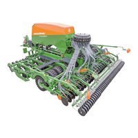
Amazone Cirrus 03 Operating Manual (320 pages)
Large area seed drill
Brand:
Amazone
| Category:
Farm Equipment
| Size: 59.47 MB
Table of Contents
Table of Contents
5
1 User Information
12
Purpose of the Document
12
Locations in the Operating Manual
12
Diagrams
12
2 General Safety Instructions
14
Obligations and Liability
14
Representation of Safety Symbols
16
Organisational Measures
17
Safety and Protective Equipment
17
Informal Safety Measures
17
User Training
18
Safety Measures in Normal Operation
19
Danger from Residual Energy
19
Maintenance and Repair Work, Fault Elimination
19
Design Changes
20
Spare and Wear Parts and Aids
21
Cleaning and Disposal
21
User Workstation
21
Warning Symbols and Other Labels on the Implement
22
Positions of Warning Symbols
30
Dangers in Case of Non-Observance of the Safety Instructions
33
Safety-Conscious Working
33
Safety Information for Users
34
General Safety Instructions and Accident Prevention Instructions
34
Hydraulic System
38
Electrical System
39
Attached Implements
39
Brake System
40
Tyres
41
Operation of the Seed Drill
41
PTO Shaft Operation
42
Cleaning, Maintenance and Repair
42
3 Loading and Unloading the Low-Bed Trailer for Delivery
43
Preparing the Implement for Loading and Unloading
43
Loading the Implement
45
Unloading the Implement
46
4 Product Description
47
Main Assemblies of the Implement
48
Overview of Assembly Groups
49
Safety and Protective Equipment
53
Overview - Supply Lines between the Tractor and the Implement
54
Transportation Equipment
56
Intended Use
57
Danger Areas and Danger Points
58
Rating Plate and CE Mark
59
Technical Data
60
Road Transport Data
62
Necessary Tractor Equipment
63
Noise Production Data
63
5 Layout and Function
64
Control Terminal for Implements with ISOBUS System
65
Twinterminal
65
Service Brake System
66
Parking Brake
67
Dual-Circuit Pneumatic Service Brake System
67
Hydraulic Service Brake System
68
Implements Without Independent Service Brake System
68
Accessories Kit with the Operating Manual
69
Radar
69
Controlling the Implement with the Control Terminal
70
Soil Tillage
70
T-Pack S
71
T-Pack in
71
T-Pack U
72
Crushboard
73
Tractor Wheel Mark Eradicator
74
Two Row Disc Array
74
Roller
76
Furrow Ridge Leveller
78
Hopper
79
One Chamber Hopper
79
Two Chamber Hopper
79
Filling Auger
80
Fill Level Monitoring
81
Metering
82
Metering Roller Diagram Table
84
Table - Metering Rollers, Seed
88
Table - Metering Rollers, Fertiliser
89
Metering - One Chamber System
90
Metering - Two Chamber System
90
Calibrating the Spread Rate
92
Automatic Seed Rate Increase
95
Spreading Seed with Wide Row Spacing
95
Seed Pre-Metering
96
Blower Fan
97
One Chamber System Blower Fan Speed
99
Two Chamber System Blower Fan Speed
100
Connecting the Blower Fan to the Tractor Hydraulics
101
Blower Fan Connection to the Tractor PTO Shaft (On-Board Hydraulic System)
102
Distributor Head
103
Shutter Distributor Head
103
Segment Distributor Head
104
Seed Tube Monitoring
104
Rotec-Pro Control Coulter (Optional Equipment)
105
Twintec+ Double-Disc Coulter (Optional Equipment)
107
Coulter Pressure, Hydraulically Adjustable
109
Exact Following Harrow (Optional Equipment)
110
Exact Following Harrow Tine Position
110
Exact Following Harrow Pressure Adjustment
111
Roller Harrow (Optional Equipment)
112
Track Marker
113
Tramlines
114
Examples for Creating Tramlines
116
Tramline Rhythm 4, 6 and 8
118
Tramline Rhythms 2 and 21
119
One-Sided Switching
120
One-Sided Switching for Implements with a Shutter Distributor Head
121
One-Sided Switching for Implements with a Segment Distributor Head
121
One-Sided Switching for Implements with 2 Distributor Heads
123
Double Tramline Switching
126
Tramline Marker
127
Work Floodlights
127
Camera System
127
Greendrill
128
6 Initial Commissioning
129
Checking the Suitability of the Tractor
130
Calculating the Actual Values for the Total Tractor Weight, Tractor Axle Loads and Tyre Load-Bearing Capacity, as Well as the Required Minimum Ballast Weight
131
Data Required for the Calculation (Hitched Implement)
132
Of the Tractor for Assurance of the Steering Capability
133
Calculation of the Actual Front Axle Load of the Tractor T
133
Calculation of the Actual Total Weight of the Combined Tractor and Implement
133
Tat
133
Calculation of the Actual Rear Axle Load of the Tractor T
133
Tractor Tyre Load Capacity
133
H Tat
133
Table
134
Requirements for Tractor Operation with Trailed Implements
135
Securing the Tractor/Implement against Unintentional Start-Up and Rolling
136
Installation Regulations for the Hydraulic Fan Drive Connection
137
7 Coupling and Uncoupling the Implement
138
Dual-Circuit Pneumatic Service Brake System
140
Coupling the Brake and Supply Lines
142
Uncoupling the Supply and Brake Line
144
Control Element for the Dual Circuit Pneumatic Brake System
145
Position of the Brake Load Adjustment Lever for the Dual-Circuit Pneumatic Service Braking System
146
Hydraulic Service Brake System
147
Coupling the Hydraulic Service Brake System
147
Uncoupling the Hydraulic Service Brake System
149
Hydraulic Hose Lines
151
Coupling the Hydraulic Hose Lines
151
Uncoupling the Hydraulic Hose Lines
152
Coupling the Implement to the Tractor
153
Coupling the T-Pack U
155
Coupling the Cirrus to the Tractor
155
Uncoupling the Implement
160
Connect/Disconnect the PTO Shaft Driven Hydraulic Pump
164
Connecting the Hydraulic Pump
164
Uncoupling the Hydraulic Pump
165
8 Settings
166
Swivel the Holding Pipe for the Lighting
167
Crushboard
167
Disc Array
168
Moving the Wheel Mark Eradicator into Working Position (on the Field)
170
Moving the Wheel Mark Eradicator into Transport Position
170
Repositioning the Low Level Sensor
171
Installing/Removing the Metering Roller
171
Calibrating the Spread Rate
174
Calibrating the Spread Rate Cirrus 3003 Compact / Cirrus 3503 Compact / Cirrus 4003 / Cirrus 4003-2 Cirrus 6003-2 with 1 Distributor Head
175
Calibrating the Spread Rate Cirrus 6003-2 with 2 Distributor Heads
176
Calibrating the Spread Rate Cirrus 4003-C / Cirrus 4003-2C / Cirrus 6003-2C
178
Setting the Blower Fan Speed
180
Setting the Blower Fan Speed Via the Flow Control Valve of the Tractor
181
Setting the Blower Fan Speed on Tractors Without Flow Control Valve
181
Set the Blower Fan Speed When Connecting the Hydraulic Motor to the Tractor PTO Shaft
181
Pressure Relief Valve with Round Outer Contour
182
Basic Setting of the Pressure Relief Valve
182
Blower Fan Speed Setting
182
Pressure Relief Valve with Hexagonal Outer Contour
183
Basic Setting of the Pressure Relief Valve
183
Blower Fan Speed Setting
183
Setting the Blower Fan Speed Monitoring
183
Pressure Monitoring in the Two Chamber Hopper
184
Rotec-Pro Control Coulter - Adjusting the Placement Depth
185
Positioning the Depth Limiting Discs
185
Setting the Coulter Pressure
187
Adjusting the Automatic Seed Rate Increase
187
Twintec+ Double-Disc Coulter - Adjusting the Placement Depth
188
Adjusting the Seed Placement Depth Range
188
Adjusting the Seed Placement Depth
189
Setting the Coulter Pressure
191
Adjusting the Harrow Tines - Twintec+ Double-Disc Coulter
192
Adjusting the Pitch of the Harrow Tines
192
Adjusting the Working Depth of the Harrow Tines
193
Putting the Harrow Tines into Parking Position
193
Adjusting the Furrow Ridge Levellers
194
Exact Following Harrow
195
Moving the Exact Following Harrow to the Working/Transport Position
195
Exact Following Harrow Tine Position
196
Exact Following Harrow Pressure Adjustment
196
Roller Harrow
197
Adjusting and Testing the Roller Pressure on the Ground
197
Adjusting the Inclination of the Harrow Tines
198
Adjusting the Working Depth of the Harrow Tines
199
Track Marker
200
Track Marker Transport Lock (Not Required on Implements with Foldable Booms)
201
One-Sided Switching
202
Activate One-Sided Switching for Implements with One Distributor Head
202
Activate One-Sided Switching for Implements with Two Distributor Heads
203
Adjusting the Tramline Marker
204
Move the Tramline Marker to Working Position
204
Move the Tramline Markers to the Transport Position
205
Adjusting the Track Discs for the Tractor Track Width
205
Moving the Double-Tramline Marker into Working / Transport Position
209
Folding and Unfolding the Ladder of the Greendrill
210
Unfolding the Ladder
210
Folding the Ladder
211
Moving the Transport Safety Bar into Transport/Parking Position
212
Moving the Transport Safety Bar to Transport Position
212
Moving the Road Safety Bar into Parking Position
212
9 Transportation
213
Set the Implement to Road Transport Mode
213
Legal Regulations and Safety
214
10 Use of the Implement
219
Work Commencement
221
Unfolding/Folding the Implement Booms
223
Unfolding the Implement Sections
223
Folding the Implement Sections
225
Filling the Hopper
227
Opening/Closing Tarpaulin
229
Open/Close the Hopper Cover
231
Filling Auger for Rigid Implements
235
Move the Filling Auger into the Filling Position
235
Residual Emptying of the Filling Auger
238
Moving the Filling Auger into the Transport Position
239
Filling Auger for Folding Implements
241
Move the Filling Auger into the Filling Position
241
Using the Filling Auger to Fill the Hopper
244
Residual Emptying of the Filling Auger
246
Moving the Filling Auger into the Transport Position
246
During Operation
248
Overview of Checks
248
Checking the Placement Depth of the Seed
249
Turning at End of the Field
249
End of Work in the Field
250
Emptying the Hopper And/Or the Metering Unit
251
One Chamber Hopper Quick Emptying
251
Two Chamber Hopper Quick Emptying
252
Hopper Residual Emptying
253
Emptying the Metering Unit
253
11 Faults
254
Residual Seed Volume Indicator
254
Deviations between the Preset and Actual Seeding Rates
255
Failure of the Control Terminal During Operation
256
Fault Table
258
12 Cleaning, Maintenance and Repairs
259
Fuse
259
Securing the Connected Implement
260
Cleaning the Implement
260
Clean the Distributor Head
263
Cleaning the Shutter Distributor Head
263
Cleaning the Segment Distributor Head
264
Shutdown of the Implement over a Long Period of Time
264
Setting and Repair Work (Specialist Workshop)
265
Drawbar Pipe Length Adjustment (Specialist Workshop)
265
Replacing the Double-Disc Coulter Bearing (Specialised Workshop)
267
Exchanging the Exact Following Harrow and the Roller Harrow with each Other (Specialised Workshop)
268
Preparing the Roller Harrow
268
Preparing the Exact Following Harrow
269
Exchanging the Exact Following Harrow with the Roller Harrow
270
Adjusting the Tramlines on the Shutter Distributor Head
272
Adjusting the Tramline Track Width on the Shutter Distributor Head (Specialised Workshop)
272
Adjusting the Tramline Wheelmark Width on the Shutter Distributor Head (Specialised Workshop)
273
Adjusting the Tramlines on the Segment Distributor Head
275
Adjusting the Tramline Track Width on the Segment Distributor Head
275
Adjusting the Tramline Wheelmark Width on the Segment Distributor Head
276
Replacing the Segment in the Segment Distributor Head
276
Connecting the Tramline Segments
278
Deactivating the Active Tramline Flaps
278
Mount the Plugs in the Shutter Distributor Head for Spreading Seed with Wide Row Spacing
279
Mount the Plugs in the Segment Distributor Head for Spreading Seed with Wide Row Spacing
279
Check and Replace the Disc Array Discs (Workshop Work)
280
Repairs to the Pressure Tank (Workshop)
281
Lubrication
282
Greasing Points - Overview
283
Maintenance Schedule - Overview
286
Checking the Tensioned Crosspiece When Coupling the Implement
289
Checking the Tensioned Crosspiece and Drawbar
289
Check the Drawbar Tightening Torques
289
Check the Transport Locking Mechanism of the Implement Booms
290
Checking and Readjusting the Twintec+ Disc Bearings
291
Checking the Disc Bearing
291
Readjusting the Disc Bearings
291
Dismounting the Twintec+ Seed Line
292
Checking / Replacing the Twintec+ Inner Scraper
292
Checking / Replacing the Twintec+ Closers
293
Checking / Replacing the Twintec+ Baffle Lip
293
Checking / Replacing the Twintec+ Press Roller
294
Checking / Readjusting / Replacing the Twintec+ Scraper
294
Tyre Inflation Pressure and Wheel Nut Tightening Torque
295
Roller with Integrated Running Gear
295
T-Pack in
297
T-Pack S
297
T-Pack U
297
On-Board Hydraulics - Oil Check and Oil Filter Change
298
Inspection Criteria for Hydraulic Hose Lines before Every Start-Up
300
Inspection Criteria for Hydraulic Hose Lines Using the Maintenance Schedule
300
Identification of Hydraulic Hose Lines
301
Installing and Removing Hydraulic Hose Lines
302
Service Brake System (All Variants)
303
General Visual Inspection of the Service Brake System
303
General Function Check of the Service Brake System
303
Checking the Service Brake System for Safe Operating Condition (Specialist Workshop)
304
Service Brake System (Dual-Circuit Pneumatic Service Brake System)
304
Exterior Inspection of the Compressed Air Tank
304
Checking the Pressure in the Compressed Air Tank (Specialist Workshop)
304
Leak Test (Specialist Workshop)
305
Cleaning the Line Filters (Specialist Workshop)
305
Bolt Tightening Torques
306
13 Hydraulic Diagram
308
Hydraulic Diagram - Cirrus 3003/3503 Compact
308
Hydraulic Diagram Cirrus 4003 (C)
310
Hydraulic Diagram Cirrus 4003-2(C)
312
Hydraulic Diagram Cirrus 6003-2(C)
314
Hydraulic Diagram Cirrus 6003-2(C) with Twintec+ Coulters
316
Advertisement
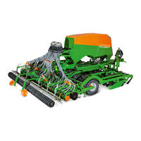
Amazone Cirrus 03 Operating Manual (368 pages)
Large area seed drill
Brand:
Amazone
| Category:
Farm Equipment
| Size: 65.73 MB
Table of Contents
Table of Contents
5
1 User Information
13
2 General Safety Instructions
14
Representation of Safety Symbols
16
Organisational Measures
17
User Training
18
Safety Measures in Normal Operation
19
Design Changes
20
Spare and Wear Parts and Aids
21
Warning Symbols and Other Labels on the Implement
22
Position of Warning Symbols
29
Dangers in Case of Non-Compliance with the Safety Instructions
31
Safety Information for Users
32
Hydraulic System
36
Electrical System
37
Brake System
38
Tyre
39
PTO Shaft Operation
40
Cleaning, Maintenance and Repair
41
3 Loading and Unloading the Low-Bed Trailer for Delivery
42
Loading the Flat-Bed Trailer
44
Unloading the Implement
45
4 Product Description
47
Main Assembly Groups of the Implement
49
Overview of Assembly Groups
50
Safety and Protective Equipment
54
Overview - Supply Lines between the Tractor and the Implement
55
Transportation Equipment
58
Safety Device against Unauthorised Use
59
Proper Use
60
Danger Areas and Danger Points
61
Rating Plate and CE Mark
62
Technical Data
64
Road Transport Data
66
Required Tractor Equipment
67
5 Structure and Function
68
Control Terminal for Implements with ISOBUS System
69
AMAZONE Twinterminal
70
Brake System
71
Dual-Circuit Pneumatic Braking System
72
Stowage Compartment
73
Tractor Wheel Mark Eradicator
74
Crushboard
75
Two Row Disc Array
76
Minimum Tilldisc Disc Array
78
Pack
79
Pack U
80
Trailing Roller with Integrated Running Gear
81
Tyre Designations
82
Furrow Ridge Leveller
83
Hopper
84
Monitoring the Hopper Content
86
Conveyor Section
87
Seed Drills with One Metering Unit and Two Distributor Heads
88
Cirrus (-C)(-2C) with Two Metering Units and Two Distributor Heads
89
Cirrus (-CC)(-2CC) with Two Metering Units and Two Distributor Heads
90
Metering
91
Metering Roller Table - Figures
93
Table - Metering Rollers, Seed
96
Table - Fertiliser Metering Rollers
97
Calibrating the Spread Rate
98
Calibration - One-Chamber System
99
Calibration - Two-Chamber System
100
Metering Operation - Two-Chamber System During Operation
101
Fan Speeds - One-Chamber System
103
Fan Speeds - Two-Chamber System
104
Connecting the Blower Fan to the Tractor Hydraulics
105
Blower Fan Connection to the Tractor PTO Shaft (On-Board Hydraulic System)
106
Distributor Head
107
Seed Tube Monitoring
108
Rotec Pro Control Coulter
109
Coulter Pressure Adjustment
111
Twintec+ Double Disc Coulter
112
Seed Placement Depth Range
113
Coulter Pressure
114
Fertec Single-Disc Coulter
115
Exact Following Harrow
116
Exact Following Harrow Tine Position
117
Roller Harrow
118
Track Marker
120
Seeding Variations Adjustable on the Control Terminal
121
Tramlines
122
Tramline Rhythm, Tabular Determination
123
Tramline Rhythm, Graphic Determination
130
Track Width / Wheelmark Width of the Cultivating Tractor
132
One-Sided Switching
133
One-Sided Switching, Mechanically Adjustable for Implements with 1 Distributor Head
134
One-Sided Switching with Two Distributor Heads, Except Cirrus (-CC)
135
Double Tramline Control for Implements with 6 M Working Width
138
Tramline Marker
139
Work Floodlights
140
Catch Crop Seed Drill Greendrill
141
6 Initial Operation
142
Checking the Suitability of the Tractor
143
Data Required for the Calculation (Hitched Implement)
145
Calculation of the Actual Total Weight of the Combined Tractor and Implement
146
Table
147
Requirements for Tractor Operation with Trailed Implements
148
Secure the Tractor / Implement against Unintentional Starting and Rolling Away
149
Fan Drive - Hydraulic Connection
151
7 Coupling and Uncoupling the Implement
152
Dual-Circuit Pneumatic Braking System
154
Coupling the Brake and Supply Lines
156
Uncoupling the Supply and Brake Line
158
Control Elements for the Dual-Circuit Pneumatic Braking System
159
Hydraulic Brake System
161
Uncoupling the Hydraulic Brake System
163
Hydraulic Hose Lines
165
Uncoupling the Hydraulic Hose Lines
166
Coupling the Implement to the Tractor
167
Coupling the T-Pack U
169
Uncoupling the Implement
173
Connect/Disconnect the PTO Shaft Driven Hydraulic Pump
176
Connecting the Hydraulic Pump
177
8 Settings
178
Moving the Tractor Wheel Mark Eradicator into Working and Transport Position
179
Crushboard Working Depth Adjustment
180
Disc Array
181
Setting the Side Panels
182
Cutting Disc Array
183
Repositioning the Low Level Sensor
184
Calibrating the Spread Rate
188
Calibration - Seed Drills with One Metering Unit and One Distributor Head
189
Calibration - Seed Drills with 1 Metering Unit and 2 Distributor Heads
190
Calibration - Seed Drills with Two Metering Units and One Distributor Head
192
Calibration - Cirrus (-C)(-2C) with Two Metering Units and Two Distributor Heads
193
Calibration - Cirrus (-CC)(-2CC) with Two Metering Units and Two Distributor Heads
195
Calibrating Metering Unit 2
196
Admixtures
197
Adjusting the Fan Speed
198
Setting the Fan Speed - on the Flow Control Valve of the Tractor
199
Pressure Relief Valve with Round Outer Contour
200
Pressure Relief Valve with Hexagonal Outer Contour
201
Fan Speed Monitoring
202
Rotec Pro Control Coulter
203
Adjusting the Depth Control Discs/Wheels
204
Setting the Coulter Pressure
206
Twintec+ Double Disc Coulter
207
Adjusting the Placement Depth
208
Adjusting the Harrow Tines
211
Harrow Tine Working Depth Adjustment
212
Putting the Harrow Tines into Parking Position
213
Adjusting the Furrow Ridge Levellers
214
Fertec Single-Disc Coulter
215
Exact Following Harrow
216
Exact Following Harrow Tine Position
217
Roller Harrow
218
Adjusting the Tilt of the Harrow Tines
219
Adjusting the Working Depth of the Harrow Tines
220
Track Marker
221
Track Marker Transport Lock (Rigid Implements Only)
222
Activating the One-Sided Switching
223
One-Sided Switching, Electronically Adjustable for Implements with 1 Distributor Head with Max. 32 Connections
224
One-Sided Switching with Two Distributor Heads
225
Adjusting the Tramline Marker
226
Moving the Tramline Marker into Transport Position
227
Adjusting the Track Discs to the Tractor Track Width
228
Moving the Double Tramline Marker into Working / Transport Position
231
Moving the Road Safety Bar into Transport/Parking Position
233
9 Transportation
234
Legal Regulations and Safety
235
Safety During Road Transport
237
10 Use of the Implement
240
Initial Operation
242
Moving the Implement into Working Position
243
Unfolding/Folding the Implement Booms
244
Unfolding the Implement Sections
245
Folding the Implement Sections
246
Filling the Hopper
250
Opening/Closing the Roller Tarpaulin
252
Opening/Closing the Hopper Cover
254
Filling Auger for Rigid Implements
258
Residual Emptying of the Filling Auger
261
Moving the Filling Auger into Transport Position
262
Filling Auger for Folding Implements
264
Using the Filling Auger to Fill the Hopper
267
Residual Emptying of the Filling Auger
269
During Operation
271
Checking the Placement Depth of the Seed and the Fertiliser
272
End of Work on the Field
273
Emptying the Hopper And/Or the Metering Unit
274
Two Chamber Hopper Quick Emptying
275
Hopper Residual Emptying
276
11 Faults
277
Deviations between the Preset and Actual Seeding Rates
278
Failure of the Control Terminal During Operation
279
Fault Table
281
12 Cleaning, Maintenance and Repairs
282
Safety of the Implement Coupled
284
Safety When Working on Hydraulic Hose Lines
285
Safety through Labelling the Hydraulic Hose Lines
286
Safety When Cleaning the Implement
287
Safety When Working on the Distributor Head
289
Clean the Distributor Head
290
Cleaning the Hopper
291
Lubrication Schedule
293
Lubrication Points
294
Maintenance Schedule
298
Adjustment and Maintenance Work
301
Checking the Tensioned Crosspiece When Coupling the Implement
302
Check the Transport Locking Mechanism of the Implement Booms
303
Tyre Inflation Pressure and Wheel Nut Tightening Torque
304
Pack in
306
On-Board Hydraulics - Oil Check and Oil Filter Change
307
Parking the Implement for a Longer Period of Time
309
Work to be Performed in a Specialist Workshop
310
Drawbar Pipe Length Adjustment
312
Check and Replace the Spring Element Bearing
315
Coulter Body Adjustment - Fertec Single-Disc Coulter
316
Adjusting the Tramlines on the Distributor Head
317
Adjusting the Tramline Track Width on the Distributor Head
318
Removing and Installing the Segment in the Distributor Head
319
Electrical Connection of the Tramline Segments
320
Deactivating Tramline Segments
321
Check and Replace the Disc Array Discs
322
Replacing the Grid on the Rotec Pro Control Coulter
323
Checking and Readjusting the Twintec+ Disc Bearings
324
Dismounting the Twintec+ Seed Line
326
Checking / Replacing the Twintec+ Seed Catcher
327
Checking / Replacing the Twintec+ Baffle Lip
328
Checking / Replacing the Twintec+ Press Roller
329
Check / Set Swivel Arm Filling Auger Cirrus 4/6003-2
330
Exchanging the Exact Following Harrow and the Roller Harrow with each Other
331
Preparing the Exact Following Harrow
332
Exchanging the Exact Following Harrow with the Roller Harrow
333
Repairs on the Pressure Hopper
335
Brake System (All Versions)
336
General Functional Check of the Brake System
337
Checking the Brake System for Safe Operating Condition at a Specialist Workshop
338
Leak Test
339
Bolt Tightening Torques
340
13 Hydraulic Diagram
342
Hydraulic Diagram - Cirrus 3003 Compact / Twintec
344
Hydraulic Diagram - Cirrus 3503 Compact / Rotec Pro
346
Hydraulic Diagram Cirrus 4003 (-C)(-CC) / Rotec Pro
348
Hydraulic Diagram - Cirrus 4003-2(C)(CC) / Rotec Pro, Part 1
350
Hydraulic Diagram - Cirrus 4003-2(C)(CC) / Rotec Pro, Part 2
352
Hydraulic Diagram - Cirrus 4003-2(C)(CC) / Twintec+, Part 1
354
Hydraulic Diagram - Cirrus 4003-2(C)(CC) / Twintec+, Part 2
356
Hydraulic Diagram - Cirrus 6003-2(C)(CC) / Rotec Pro, Part 1
358
Hydraulic Diagram - Cirrus 6003-2(C)(CC) / Rotec Pro, Part 2
360
Hydraulic Diagram - Cirrus 6003-2(C)(CC) / Twintec+, Part 1
362
Hydraulic Diagram - Cirrus 6003-2(C)(CC) / Twintec+, Part 2
364
Advertisement
Related Products
Amazone Cirrus Series
Amazone Cirrus 3001
Amazone Cirrus 4001
Amazone Cirrus 6001
Amazone Cirrus 3000
Amazone Cirrus 4000
Amazone Cirrus 6000
Amazone Citan 6000
Amazone Cayros XMS
Amazone Cayros XM V
Amazone Categories
Farm Equipment
Tiller
Spreader
Desktop
Paint Sprayer
More Amazone Manuals
Login
Sign In
OR
Sign in with Facebook
Sign in with Google
Upload manual
Upload from disk
Upload from URL