Sign In
Upload
Manuals
Brands
Allison Transmission Manuals
Microphone system
AT 545
Allison Transmission AT 545 Manuals
Manuals and User Guides for Allison Transmission AT 545. We have
3
Allison Transmission AT 545 manuals available for free PDF download: Service Manual, Manual, Operator's Manual
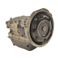
Allison Transmission AT 545 Service Manual (190 pages)
Automatic Models
Brand:
Allison Transmission
| Category:
Microphone system
| Size: 4.82 MB
Table of Contents
Table of Contents
5
Section 1. GENERAL INFORMATION
11
Scope of Manual
11
Coverage
11
Illustrations
11
Maintenance Information
11
Supplementary Information
11
Ordering Parts
11
Transmission Nameplate
11
Parts Catalog
11
General Description
14
Automatic, Four Speeds
14
Torque Converter and Lockup Clutch
14
Planetary Gearing, Clutches
14
Main Control Valve Body
14
Operating Instructions
14
Specifications and Data
14
Section 2. DESCRIPTION and OPERATION
19
Scope
19
Mounting
19
To Engine
19
To Vehicle
19
Input Drive
19
Transmission Housing
19
Torque Converter Assembly
19
And Lockup Clutch
19
Description
19
Oil Pump Assembly
20
Description
20
Operation
20
Forward Clutch and Turbine Shaft
20
Forward Clutch
20
Fourth Clutch
21
Description
21
Operation
21
Second and Third Clutch and Center Support
21
Operation of Third Clutch
21
Third Clutch
21
Second Clutch
21
Operation of Second Clutch
22
First Clutch
22
Description
22
Operation
22
Planetary Gear Unit
22
Speedometer Drive/Speed Sensor Wheel
23
Description
23
Operation
23
Governor
23
Modulator
23
Vacuum Modulator
23
Mechanical Modulator
23
Electric Modulator
23
Oil Pan and Filter
24
Description
24
Function
24
Hydraulic Retarder
24
Operation
24
Main Control Valve Assembly
25
Hydraulic System
25
System Functions
25
System Schematic
25
Filter, Pump Circuit
25
Main-Pressure Circuit (Red)
25
Converter-In (Yellow), Converter-Out (Orange), Lubrication (Green) Circuits
26
Selector Valve, Neutral, Forward Regulator Circuit (Orange and Yellow)
26
Governor Valve, Governor Circuit (Green and White)
26
Modulator Pressure Circuit
26
Clutch Circuits
27
Hold Regulator Valve
27
Automatic Upshifts
27
Automatic Downshifts
27
Downshift Inhibiting
27
Trimmer Valves
28
Priority Valve
28
Trimmer Regulator Valve
28
Torque Paths through
29
Neutral Operation
29
Section 7. ASSEMBLY of TRANSMISSION
29
First Clutch
29
Fourth Clutch
29
Forward Clutches
29
Third Clutch
29
First-Range Operation
30
Second-Range Operation
31
Third-Range Operation
32
Converter Operation (at 1500 Series Models)
32
Lockup Operation
32
Fourth-Range Operation
33
Fourth-Range Lockup Operation (at 1500 Series Models)
33
Reverse Operation
34
Section 3. PREVENTIVE MAINTENANCE
35
Scope
35
Periodic Inspection and Care
35
Importance of Proper
35
Foaming and Aerating
35
Dipstick Markings
35
Transmission Fluid Level Check Procedure
36
Preparation
36
Cold Check
37
Hot Check
37
Keeping Transmission
37
Fluid Clean
37
Transmission Fluid Recommendations
37
Recommended Automatic Transmission Fluid and Viscosity Grade
37
Transmission Fluid and Filter Change Intervals
38
Transmission Fluid Contamination
38
Examine at Fluid Change
38
Metal Particles
38
Coolant Leakage
38
Auxiliary Filter
38
Transmission Fluid and Filter Change Procedures
41
Disassembly
41
Assembly
41
Breather
42
Linkage
43
Shift Selector Lever and Control Linkage
43
Mechanical Actuator Adjustment
43
Other Linkage Adjustments
43
Adjustment of Shift Points
43
Calibrated on Test Stand or in Vehicle
43
Location of Adjusting Components
43
Checks before Adjusting Shift Points
44
Calibration by Road Test Method
44
Calibration by Speedometer Readings Method
44
Calibration by Test Stand Method
44
Transmission Stall Test and Neutral Cool-Down Check
49
Purpose
49
Stall Testing Preparation
49
Stall Test Procedures - Vehicles Without Smoke-Controlled Engines
49
Stall Test Procedures - Vehicles with Smoke-Controlled Engines
50
Neutral Cool-Down Check Procedure
50
Results
50
Preservation and Storage
50
Storage, New Transmissions
50
Preservation Methods
50
Storage, One Year - Without Transmission Fluid
50
Storage, One Year - with Transmission Fluid
51
Restoring Transmission to Service
51
Replacement of Components While Transmission Is in the Vehicle Chassis
52
Replacement of Selector Shaft Seal
52
Removal of Output Flange, Output Seal
52
Removal of Output Shaft Bearing
52
Removal of Speedometer Drive Gear or Speed Sensor Wheel and Selective Spacer
52
Replacement of Components
52
WHILE TRANSMISSION IS in the VEHICLE CHASSIS (Cont'D)
52
Installation of Speedometer Drive Gear or Speed Sensor Wheel and
52
Installation of Output Shaft Bearing
53
And Snapring
53
Installation of Output Seal
53
Installation of Output Flange
53
Troubleshooting - before
53
Removal or Operation of
53
Transmission
53
Visual Inspection
53
Vacuum Modulator Check
53
Troubleshooting - before
55
Removal and During Operation
55
Determine Cause of Trouble
55
Proper Engine Tuning
55
Hydraulic Pressure Checking
55
Procedures
55
Troubleshooting - Transmission Removed from Vehicle
55
Troubleshooting Procedures
55
Section 4. GENERAL OVERHAUL INFORMATION
69
Scope
69
Tools and Equipment
69
Improvised Tools and Equipment
69
Special Tools
70
Mechanic's Tools, Shop Equipment
76
Replacement Parts
77
Ordering Information
77
Parts Normally Replaced
77
Careful Handling
77
Dirt-Free Assembly
77
Cleaning Parts
77
Cleaning Bearings
77
Assembly
77
Inspecting Bearings
78
Keeping Bearings Clean
78
Inspecting Cast Parts, Machined Surfaces
78
Inspecting Bushings, Thrust Washers
79
Inspecting Oil Seals, Gaskets
79
Inspecting Gears
80
Inspecting Splined Parts
80
Inspecting Threaded Parts
80
Inspecting Snaprings
80
Inspecting Springs
80
Inspecting Clutch Plates
80
Inspecting Swaged, Interference-Fit
80
Parts
80
Inspecting Balls in Clutch Housings
80
Inspecting Seal Contact Surfaces
80
Assembly Procedures
81
Clutches, Pistons
81
Parts Lubrication
81
External Pipe Plugs, Hydraulic
81
Fittings
81
Oil-Soluble Grease
81
Lip-Type Seals (Metal Encased)
81
Interference-Fit Parts
81
Sleeve-Type Bearings and Bushings
81
Bearings (Ball or Roller)
81
Removing (or Installing) Transmission
82
Drain Transmission Fluid
82
Check Linkages and Lines
82
Remove, Clean Transmission
82
Transmission Installation
82
Wear Limits
82
Spring Specifications
82
Torque Specifications
82
Section 5. DISASSEMBLY of TRANSMISSION
83
Scope
83
General Information
83
Removal of Exterior Hoses and Lines
83
Transmission Disassembly
83
Mounting of Transmission in Table-Mounted Holding Fixture
83
Removal of Torque Converter
84
Removal of Vacuum Modulator, Mechanical Actuator
84
Removal of Breather
84
Assembly
84
Removal of Governor
85
Removal of Oil Pan
85
Removal of Filter
85
Removal of Main Control Valve Body
85
Removal of Pump
87
Removal of Forward Clutch and Turbine Shaft
88
Removal of Retarder Components, Forward Clutch and Turbine Shaft
88
Pump Assembly
88
Removal of Fourth Clutch
89
Removal of Third Clutch
89
Removal of Center Support Assembly
89
Removal of Planetary Gearing
90
Removal of Second Clutch
91
Removal of First Clutch
91
Removal of Output Shaft Seal and Bearing
92
Section 6. REBUILD of SUBASSEMBLIES
93
Scope
93
General Information for Subassembly Rebuild
93
Inspecting and Testing Torque Converter
93
Preliminary Inspection
93
End Play Check
93
Leak Check
94
Inspection of Hub
94
Preparation for Reuse of Converter
94
Torque Converter Assembly - at 543 Models
94
Preliminary Check of End Play
94
Replacement of Needle Bearing Assembly in Stator Assembly
96
Assembly
96
Governor
99
Main Control Valve Body
100
Assembly
105
Transfer Plate Assembly
105
Oil Pump and Front
106
Support Assembly
106
Installation of Stator Shaft and Bushing
108
Pump Gear Clearance Check
109
Assembly
110
Forward Clutch and Turbine Shaft Assembly
112
Disassembly
112
Checking Clutch Pack Clearance (Models Without Wave Plate)
114
Assembly
117
Retarder Housing Assembly
117
Checking Clutch Pack Clearance
118
Center Support Assembly
119
Rework of Center Support Piston Retainer Locating Notches
120
Assembly
120
Planetary Gear Unit
121
Assembly
122
Transmission Main Housing Assembly
124
Disassembly
124
Assembly
125
Planetary Carrier Assemblies
125
Inspection
126
Removal of Pinion Components
127
Replacing Bushing in Front Planetary Carrier
127
Installation of Pinion Components
128
Filter
147
Oil Pan
147
Installation of Governor, Modulator, and Torque Converter
148
Governor
148
Vacuum Modulator
148
Torque Converter Assembly
149
Removal of Transmission from Overhaul Stand and Installation of External Components
150
Supporting Transmission
150
Determining Third Clutch Clearance
150
Installing Retarder Valve Body
150
Installing PTO Cover
150
Installing Neutral Start Switch, Speedometer Components
150
Shift Lever Installation
150
Checking and Adjusting
151
Shift Points
151
Power Takeoff Components
151
(Models Without Retarder)
151
Existing Installation
151
Determining Turbine-Driven PTO
151
Backlash
151
New Installation
151
Section 8. WEAR LIMITS and
153
Wear Limit Data
153
Spring Data
153
Section 9. CUSTOMER SERVICE
167
Owner Assistance
167
Service Literature
168
Advertisement
Allison Transmission AT 545 Manual (52 pages)
Brand:
Allison Transmission
| Category:
Microphone system
| Size: 0.53 MB
Table of Contents
Table of Contents
4
Description Page
5
Sectioni
8
Preventive Maintenance
8
Periodic Inspection and Care
8
Importance of Proper Fluid Level
8
Dipstick Markings
8
Fluid Check Procedure
10
Keeping Fluid Clean
11
Recommended Automatic Transmission Fluid
11
And Viscosity Grade
11
Fluid and Filter Change Intervals
12
Fluid and Filter Change Procedure
13
Fluid Contamination
15
Auxiliary Filter
16
Breather
17
Transmission Stall Test and Neutral Cool-Down Check
17
Removing Transmission
20
Draining Transmission
20
Disconnecting Controls
20
Uncoupling Engine from Driveline
21
Removing Mounting Bolts
22
Removing Transmission
22
Repair Instructions
22
Preparing Transmission for Installation
24
Checking Input Components
24
Checking Torque Converter Position
24
Installing Parking Brake and Output Flange
25
Installing Shift Selector Lever
26
Installing Power Takeoff (PTO)
27
Installing Shift Modulation Control
28
Installing Fill Tube and Drain Plug
29
Installing Neutral Start and Reverse Signal Switches
30
Installing Retarder Controls
30
Checking Breather
31
Preparing Vehicle for Transmission Installation
32
Checking Flexplate, Engine Features
32
Checking Chassis, Driveline
34
Checking Cooler, Tubes, Hoses, Fittings
34
Checking Controls
35
Installing Transmission into Vehicle
36
Handling
36
Coupling to Engine
36
Installing Transmission Mounting Components
37
Coupling to Driveline
38
Installing Vacuum or Air Modulator Control
38
Connecting Cooler, Vacuum Lines, Air Lines
39
Connecting Retarder Controls
39
Connecting Shift Selector Control
40
Installing, Adjusting Mechanical Modulator Control
41
Connecting Power Takeoff Controls
42
Connecting Parking Brake Control
42
Connecting Speedometer Drive
42
Filling the Transmission
43
Checks and Adjustment
44
Installation Checklist
44
Road Test and Vehicle Operation Checklist
47
Customer Service
49
Owner Assistance
49
Service Literature
51
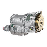
Allison Transmission AT 545 Operator's Manual (48 pages)
On-Highway Transmissions
Brand:
Allison Transmission
| Category:
Microphone system
| Size: 0.59 MB
Table of Contents
Warnings, Cautions, and Notes
3
Table of Contents
4
Keeping that Allison Advantage
6
Typical AT, MT, and HT Model Transmissions
7
A Brief Description of the Allison Automatic
8
Torque Converter
8
Lockup Clutch (at 1500, MT(B) 600, HT 700)
8
Shift Selectors
10
Allison Automatics
11
Typical AT, MT, HT Shift Selector Positions
11
Range Selection - at 500 Series and at 1500 Series with a Second Neutral (Park)
12
Range Selection - MT 650; MT(B) 653DR
16
Range Selection - HT 750CR, HT 754CR, MT(B) 654CR
18
Range Selection - HT 750DR, HT 750DR DB
20
Driving Tips
22
Throttle Control
22
Downshift Inhibit Feature
22
Operating in Cold Weather
22
Using the Engine for Downhill Braking to Slow the Vehicle or Equipment
23
Using the Hydraulic Retarder
23
Auxiliary Transmission
25
Two-Speed Axle
25
Towing or Pushing
25
Parking Brake
25
Driving on Ice or Snow
26
Rocking out
26
Temperatures
26
Power Takeoff Operation
28
Engine-Driven PTO
28
Converter-Driven PTO
28
Care and Maintenance
30
Periodic Inspections
30
Prevent Major Problems
31
Importance of Proper Fluid Level
31
Transmission Fluid Check Procedure
32
Cold Check
33
Hot Check
34
Dropbox Fluid Check Procedure
34
Keeping Fluid Clean
35
Recommended Automatic Transmission Fluid and Viscosity Grade Non-MT 643R Transmissions
35
MT 643R Transmissions
36
Fluid and Filter Change Intervals
37
Fluid Contamination
38
Auxiliary Filter
40
Customer Service
41
Owner Assistance
41
Service Literature
43
Allison Transmission Distributors
44
Allison Transmission Regional Offices
47
Advertisement
Advertisement
Related Products
Allison Transmission AT 540
Allison Transmission AT 542N
Allison Transmission AT 542R
Allison Transmission AT 542NFE
Allison Transmission AT 543
Allison Transmission AT 545N
Allison Transmission AT 545R
Allison Transmission AT 542
Allison Transmission AT 542NR
Allison Transmission AT 545NR
Allison Transmission Categories
Microphone system
Control Unit
Controller
More Allison Transmission Manuals
Login
Sign In
OR
Sign in with Facebook
Sign in with Google
Upload manual
Upload from disk
Upload from URL