Sign In
Upload
Manuals
Brands
Allied Telesis Manuals
Switch
x530 Series
Allied Telesis x530 Series Manuals
Manuals and User Guides for Allied Telesis x530 Series. We have
3
Allied Telesis x530 Series manuals available for free PDF download: Installation Manual, Quick Installation Manual
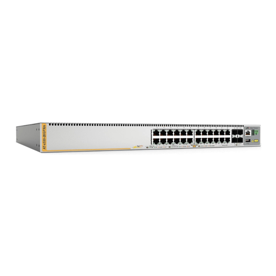
Allied Telesis x530 Series Installation Manual (200 pages)
Stackable Gigabit Layer 3 Ethernet Switches
Brand:
Allied Telesis
| Category:
Switch
| Size: 9.45 MB
Table of Contents
Table of Contents
5
Preface
13
Document Conventions
14
Contacting Allied Telesis
15
Chapter 1: Overview
17
Front and Rear Panels
18
Figure 1: Front Panel of the X530-10Ghxm Switch
18
Figure 2: Front Panel of the X530-18Ghxm Switch
18
Figure 3: Front Panel of the X530-28Gtxm Switch
18
Figure 4: Front Panel of the X530-28Gpxm Switch
19
Figure 5: Front Panel of the X530-28GSX Switch
19
Figure 6: Front Panel of the X530-52Gtxm Switch
19
Figure 7: Front Panel of the X530-52Gpxm Switch
20
Figure 8: Back Panel of the X530-10Ghxm, X530-18Ghxm, X530-28Gpxm, and X530-52Gpxm Poe Switches
20
Figure 9: Back Panel of the X530-28GSX, X530-28Gtxm and X530-52Gtxm Non-Poe Switches
20
Features
21
X530 Models
21
Table 1: Basic Features
21
Power over Ethernet
22
SFP/SFP+ Transceiver Ports
23
Leds
24
Installation Options
24
Management Software and Interfaces
24
Management Methods
25
Management Panel
26
Figure 10: Management Panel
26
Copper Ports
27
Table 2: Copper Port Features
27
Table 3: X530-10Ghxm Switch Copper Port Specifications
28
Table 4: X530-18Ghxm Switch Copper Port Specifications
29
Table 5: X530-28Gtxm Switch Copper Port Specifications
30
Table 6: X530-28Gpxm Switch Copper Port Specifications
31
Table 7: X530-52Gtxm Switch Copper Port Specifications
32
Duplex Mode
33
Table 8: X530-52Gpxm Switch Copper Port Specifications
33
Wiring Configuration
34
Maximum Distance
34
Cable Requirements
34
Port Pinouts
34
Power over Ethernet
35
Poe Standards
35
Powered Device Classes
36
Power Budget
36
Table 9: IEEE Powered Device Classes
36
Port Prioritization
37
Wiring Implementation
38
Eco-Friendly Button
39
Leds
40
Figure 11: X530-10Ghxm Copper Ports
40
Table 10: X530-10Ghxm Copper Ports 1 - 8 LED Functions
40
Figure 12: X530-18Ghxm Copper Ports
41
Table 11: X530-18Ghxm Copper Ports 1 - 16 LED Functions
42
Figure 13: X530-28Gtxm and X530-52Gtxm Copper Ports Leds
43
Table 12: X530-28Gtxm Copper Ports 1 - 24 LED Functions
43
Table 13: X530-52Gtxm Copper Ports 1 - 48 LED Functions
44
Figure 14: X530-28Gpxm and X530-52Gpxm Copper Ports Leds
45
Table 14: X530-28Gpxm Copper Ports 1 - 24 LED Functions
46
Table 15: X530-52Gpxm Copper Ports 1 - 48 LED Functions
48
Leds for the SFP Ports
49
Figure 15: SFP Port Leds on the X530-28GSX Switch
49
S1 and S2 SFP+ Port LEDS
50
Table 16: X530-28GSX SFP Network / Stacking Leds
50
Figure 16: Link and Activity Leds for the 1Gbps/10Gbps SFP+ Ports
51
Switch ID LED
52
Figure 17: Switch ID LED
52
Table 17: Link and Activity Status Leds for the 1Gbps and 10Gbps Ports
52
Figure 18: Switch ID LED Description
53
Vcstack Feature
54
USB Port
55
Console Port
56
Power Supplies
57
Software and Hardware Releases
58
Table 18: Software and Hardware Releases
58
Chapter 2: Virtual Chassis Stacking
59
Overview
60
Stacking Guidelines
61
Stack Trunks
63
Table 19: Trunk Ports
63
Stack Trunks of the Default 10Gbps SFP+ S1 and S2 Stacking Ports
64
Figure 19: Stack Trunks of Default S1 and S2 Ports
65
Figure 20: Stack Trunks Using All Four Ports
67
Figure 21: 10Gbps Stack Trunk with both SFP+ Fiber Optic Transceivers and SP10TW Direct Connect Cables
68
Stack Trunks of 5Gbps Copper Ports
69
Figure 22: Trunks of 5Gbps Multi-Speed Ports for Stacks of Two Switches
70
Figure 23: Trunks of 5Gbps Ports for Stacks of Three Switches
71
Stack Trunks of 1Gbps Copper Ports
72
Figure 24: Stack Trunks of 1Gbps Copper Ports
73
Stack Trunks of 1Gbps SFP Ports 1 to 24 on X530-28GSX Switches
74
Figure 25: Trunks of 1Gbps SFP Copper Ports for Stacks of Three X530-28GSX Switches
75
Invalid Stack Trunks
76
Example 1
76
Example 2
76
Figure 26: Invalid Stack Trunk with an Intermediary Networking Device
76
Figure 27: Invalid Stack Trunk with One Port Used Per Switch
76
Example 3
77
Example 4
77
Figure 28: Invalid Stack Trunk with Different Numbers of Links
77
Figure 29: Invalid Stack Trunk with Different Port Types
77
Master and Member Switches
78
Selection of the Master Switch
78
Switch ID Numbers
80
Optional Feature Licenses
81
Mixed Switch Stacks
82
Stack Mixed-Mode Licenses
82
Stack Mixed-Mode Commands
83
Trunk Ports
83
Optional Licenses
83
Alliedware Plus
83
Guidelines
83
Planning the Stack
85
Configuring Mixed-Mode Vcstacking
86
Stacking Worksheet
87
Table 20: Stacking Worksheet
87
Table 21: Stacking Worksheet Columns
88
Chapter 3: Beginning the Installation
91
Reviewing Safety Precautions
92
Choosing a Site for the Switch
97
Unpacking the Switch
98
Figure 30: Switch Shipping Box
98
Figure 31: Accessory Kit Items
99
Figure 32: Accessory Kit Items
100
Table 22: Accessory Kit Items
101
Chapter 4: Installing the Switch on a Table
103
Installing the Rubber Feet on the Switch
104
Installing the Bumper Feet with Rivets on the Switch
105
Figure 33: Parts of the Bumper Feet
105
Figure 34: Holes for Bumper Feet
106
Figure 35: Inserting the Rivet Housing into the Bumper Foot
106
Figure 36: Placing the Bumper Foot on a Base Corner Hole
107
Figure 37: Inserting the Rivet into the Bumper Foot
107
Placing the Switch on a Desk or Table
108
Chapter 5: Installing the Switch in an Equipment Rack
109
Beginning the Installation
110
Required Items
110
Switch Orientations in the Equipment Rack
110
Figure 38: Bracket Holes on the Switch
110
Figure 39: Switch Orientations in an Equipment Rack
111
Installing the Switch
112
Figure 40: Example of Attaching the Brackets to the Switch
112
Figure 41: Installing the Switch in an Equipment Rack
113
Chapter 6: Installing the Switch on a Wall
115
Switch Orientations on a Wall
116
Figure 42: Positioning the X530-28Gtxm or X530-28GSX Switch on the Wall
116
Figure 43: Positioning the X530-10Ghxm, X530-18Ghxm, X530-28Gpxm, X530-52Gtxm,Or X530-52Gpxm
117
Installation Guidelines
118
Tools and Material
118
Plywood Base for a Wall with Wooden Studs
120
Figure 44: Switch on the Wall with a Plywood Base
120
Installing a Plywood Base
121
Figure 45: Installing the Plywood Base to the Wall
121
Installing the Switch on a Plywood Base
122
Figure 46: Installing Two Brackets on the X530-28Gtxm or X530-28GSX Switch
123
Figure 47: Installing Four Brackets on the X530-10Ghxm, X530-18Ghxm, X530-28Gpxm, X530-52Gtxm or
124
Figure 48: Securing the X530-28Gtxm or X530-28GSX Switch to the Plywood Base
125
Figure 49: Securing the X530-10Ghxm, X530-18Ghxm, X530-28Gpxm, X530-52Gtxm or X530-52Gpxm Switch to the Plywood Base
126
Installing the Switch on a Concrete Wall
127
Figure 50: Marking the Locations of the Bracket Holes on a Concrete Wall
128
Figure 51: Installing the Switch on a Concrete Wall
129
Chapter 7: Building the Trunk with the Default SFP+ S1 and S2 10Gbps Stacking Ports
131
Introduction
132
Powering on the Switches Sequentially
133
Powering on the Switches Simultaneously
136
Starting a Management Session
138
Through the Console Port
138
Figure 52: Management Cable Included with Switch
138
Figure 53: VT-Kit3 Management Cable
138
Figure 54: , VT-Kit3 Management Cable with Workstation and Switch
139
With a DHCP or Dhcpv6 Server
140
Without a DHCP or Dhcpv6 Server
141
Verifying the Stack
143
Figure 55: SHOW STACK Command
143
Adding SFP+ Ports to the Stack Trunk
144
Table 23: Adding SFP+ Ports to the Default SFP+ Trunk
144
Powering on a Switch
146
Figure 56: Installing the Power Cord Retaining Clips
146
Figure 57: Connecting the AC Power Cord to the Switch
147
Figure 58: Plugging in the AC Power Cord to the Switch
147
Figure 59: Plugging in the AC Power Cord to an AC Sources
148
Chapter 8: Building the Stack with Gigabit or 5G Multi-Speed Ports
149
Introduction
150
Command Summary
151
STACK ENABLE Command
151
STACKPORT Command
151
STACK PRIORITY Command
151
STACK RENUMBER Command
153
SWITCH PROVISION Command
153
Configuring the Master Switch
154
General Steps for the Master Switch
155
Configuring the Master Switch - Part I
156
Table 24: Configuring the Master Switch to Use Gigabit or Multi-Speed 5G Ports as the Stack Trunk - Part I
156
Configuring the Master Switch - Part II
158
Table 25: Configuring the Master Switch to Use Gigabit or 5G Multi-Speed Ports as the Stack Trunk - Part II
159
Verifying the Master Switch
160
Figure 60: SHOW STACK Command on the Master Switch
160
Figure 61: SHOW RUNNING-CONFIG INTERFACE Command on the Master Switch
161
What to Do Next
162
Figure 62: Powering off the Switch
162
Configuring Member Switches
163
General Steps for the Member Switch
163
Configuring Member Switches - Part I
164
Table 26: Configuring Member Switches - Part I
164
Configuring Member Switches - Part II
165
Table 27: Configuring Member Switches - Part II
166
Verifying Member Switches
167
Figure 63: SHOW STACK Command for a Member Switch
167
Figure 64: SHOW RUNNING-CONFIG INTERFACE Command for Member Switches
168
What to Do Next
169
Powering on the Stack
170
Verifying the Stack
171
Chapter 9: Cabling the Networking Ports
173
Cabling Copper Ports
174
Installing SFP and SFP+ Transceivers
176
Figure 65: Removing the Dust Plug from an SFP+ Port
177
Figure 66: Installing SFP+ Transceivers
178
Figure 67: Removing the Dust Cover from an SFP or SFP+ Transceiver
178
Figure 68: Positioning the SFP or SFP+ Handle in the Upright Position
179
Figure 69: Connecting a Fiber Optic Cable to an SFP or SFP+ Transceiver
179
Installing SP10TW Direct Connect Cables
180
Figure 70: Removing the Dust Cover from the AT-SP10TW Cable
180
Figure 71: Installing AT-SP10TW Cables
181
Chapter 10: Troubleshooting
183
Appendix A: Technical Specifications
189
Physical Specifications
190
Dimensions
190
Figure 72: X530-10Ghxm Dimensions
190
Table 28: Product Dimensions
190
Figure 73: X530-18Ghxm Dimensions
191
Figure 74: X530-28Gtxm Dimensions
191
Figure 75: X530-28Gpxm Dimensions
191
Figure 76: X530-28GSX Dimensions
191
Weights
192
Figure 77: X530-52Gtxm Dimensions
192
Figure 78: X530-52Gpxm Dimensions
192
Table 29: Product Weights
192
Ventilation
193
Table 30: Ventilation Requirements
193
Environmental Specifications
194
Table 31: Environmental Specifications
194
Power Specifications
195
Maximum Power Consumption
195
Input Voltages
195
Table 32: Maximum Power Consumptions
195
Table 33: Input Voltages
195
Heat Dissipation
196
Table 34: Heat Dissipation
196
Copper Port Pinouts
197
Figure 79: RJ-45 Socket Pin Layout (Front View)
197
Table 35: Pin Signals for 100M/1G/2.5G/5G Base-T Connectors
197
Style Serial Console Port Pinouts
198
Table 36: RJ-45 Style Serial Console Port Pin Signals
198
USB Port
199
Table 37: USB Port Pin Signals
199
Advertisement
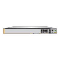
Allied Telesis x530 Series Installation Manual (128 pages)
Stackable Gigabit Layer 3+ Ethernet Switches AlliedWare Plus v5.4.8-2
Brand:
Allied Telesis
| Category:
Switch
| Size: 5.7 MB
Table of Contents
Table of Contents
5
Preface
11
Document Conventions
12
Contacting Allied Telesis
13
Chapter 1: Overview
15
Front and Rear Panels
16
Figure 1: Front Panels of the X530 Series Switches
16
Figure 2: Back Panels of the X530 Series Switches
17
Management Panel
18
Figure 3: Management Panel
18
Features
19
X530 Models
19
Twisted Pair Ports
19
Table 1: Basic Features
19
Power over Ethernet
20
SFP+ Transceiver Slots
20
Leds
20
Installation Options
21
Management Software and Interfaces
21
Management Methods
21
Twisted Pair Ports
22
Table 2: AT-X530-28Gtxm Switch Twisted Pair Port Specifications
22
Table 3: AT-X530-28Gpxm Switch Twisted Pair Port Specifications
22
Duplex Mode
23
Speed
23
Wiring Configuration
23
Cable Requirements
24
Maximum Distance
24
Table 4: Cable Requirements for Ports 1 - 24 at 100 Mbps or 1 Gbps
24
Figure 4: AT-X530-28Gtxm Twisted Pair Ports 1-24 Leds
25
Leds
25
Port Pinouts
25
Table 5: AT-X530-28Gtxm Twisted Pair Ports 1 - 24 LED Functions
25
Figure 5: AT-X530-28Gpxm Twisted Pair Ports 1-24 Leds
26
Table 6: AT-X530-28Gpxm Twisted Pair Ports 1 - 24 LED Functions
26
Power over Ethernet on the AT-X530-28Gpxm Switch
28
Poe Standards
28
Powered Device Classes
29
Power Budget
29
Port Prioritization
29
Table 7: IEEE Powered Device Classes
29
Wiring Implementation
30
SFP+ Transceiver Slots on the AT-X530-28Gtxm and AT-X530-28Gpxm Switches
31
SFP and SFP+ Transceivers
31
Leds
31
Figure 6: Link and Activity Leds for the 1 Gbps/10 Gbps SFP+ Slots
31
Table 8: Link and Activity Status Leds for the 1 Gbps and 10 Gbps Ports
32
Eco-Friendly Button
33
Vcstack Feature
34
Switch ID LED
35
Figure 7: Switch ID LED
35
Figure 8: Switch ID LED Description
36
USB Port
37
Console Port
38
Power Supply
39
Chapter 2: Virtual Chassis Stacking
41
Overview
42
Stacking Guidelines
43
10 Gbps Stack Trunks
44
Figure 9: Valid Stack Trunk Using Default Stacking Ports 27 and 28
45
Figure 10: Valid Stack Trunk Using Ports 25 to 28
46
Invalid Stack Trunks
47
Example 1
47
Example 2
47
Figure 11: Invalid Stack Trunk with an Intermediary Networking Device
47
Figure 12: Invalid Stack Trunk with One Port Used Per Switch
47
Example 3
48
Figure 13: Invalid Stack Trunk with Different Numbers of Links
48
Example 4
49
Figure 14: Invalid 10 Gbps Stack Trunk with both Fiber Optic and AT-SP10TW Direct Connect Cables
49
Master and Member Switches
50
Selection of the Master Switch
50
Switch ID Numbers
52
Optional Feature Licenses
53
Planning the Stack
54
Chapter 3: Beginning the Installation
55
Reviewing Safety Precautions
56
Choosing a Site for the Switch
60
Unpacking the AT-X530-28Gtxm or AT-X530-28Gpxm Switch
61
Figure 15: AT-X530-28Gtxm or AT-X530-28Gpxm Switch Shipping Box
61
Figure 16: Accessory Kit Items
62
Chapter 4: Installing the Switch on a Table
63
Figure 17: Parts of the Bumper Feet
63
Figure 18: Holes for Bumper Feet
64
Figure 19: Inserting the Rivet Housing into the Bumper Foot
64
Figure 20: Placing the Bumper Foot on a Base Corner Hole
65
Figure 21: Inserting the Rivet into the Bumper Foot
65
Chapter 5: Installing the Switch in an Equipment Rack
67
Installing AT-X530-28Gtxm or AT-X530-28Gpxm Switches in an Equipment Rack
68
Required Items
68
Switch Orientations in the Equipment Rack
68
Figure 22: Bracket Holes on the AT-X530-28Gtxm and AT-X530-28Gpxm Switches
68
Installing the Switch
69
Figure 23: Switch Orientations in an Equipment Rack
69
Figure 24: Example of Attaching the Brackets to the Switch
70
Figure 25: Installing the Switch in an Equipment Rack
71
Chapter 6: Installing the Switch on a Wall
73
Switch Orientations on a Wall
74
Figure 26: Positioning the AT-X530-28Gtxm Switch on the Wall
74
Figure 27: Positioning the AT-X530-28Gpxm Switch on the Wall
75
Installation Guidelines
76
Tools and Material
77
Plywood Base for a Wall with Wooden Studs
78
Figure 28: Installing the Plywood Base to the Wall
79
Figure 29: Installing the Switch on the Plywood Base
80
Installing a Plywood Base
81
Installing the Switch on a Plywood Base
82
Figure 30: Installing Two Brackets on the AT-X530-28Gtxm Switch
83
Figure 31: Installing Four Brackets on the AT-X530-28Gpxm Switch
84
Figure 32: Securing the AT-X530-28Gtxm Switch to the Plywood Base
85
Figure 33: Securing the AT-X530-28Gpxm Switch to the Plywood Base
86
Installing the Switch on a Concrete Wall
87
Figure 34: Marking the Locations of the Bracket Holes on a Concrete Wall
88
Figure 35: Installing the Switch on a Concrete Wall
89
Chapter 7: Powering on the Stack
91
Introduction
92
Installing the Power Cord Retaining Clips
93
Figure 36: Installing the Retaining Clip
93
Powering on the Switches Individually
94
Figure 37: Plugging in the AC Power Cord to the Switch
95
Figure 38: Plugging in the AC Power Cord to an AC Source
96
Powering on the Switches Simultaneously
98
Starting a Local Management Session
100
Figure 39: Connecting the Management Cable to the Console Port
100
Verifying the Stack
102
Adding Ports 25 and 26 to the Stack Trunk
103
Table 9: Adding Ports 25 and 26 to the Stack Trunk
103
Monitoring the Initialization Processes
105
Figure 40: Switch Initialization Messages
105
Figure 41: Switch Initialization Messages (Continued)
106
Figure 42: Switch Initialization Messages (Continued)
107
Chapter 8: Cabling the Networking Ports
109
Cabling Twisted Pair Ports
110
Guidelines to Handling SFP and SFP+ Transceivers
111
Installing SFP or SFP+ Transceivers in AT-X530-28Gtxm and AT-X530-28Gpxm Switches
112
Figure 43: Removing the Dust Plug from an SFP Slot
112
Figure 44: Installing an SFP Transceiver
113
Figure 45: Removing the Dust Cover from an SFP or SFP+ Transceiver
113
Figure 46: Positioning the SFP or SFP+ Handle in the Upright Position
114
Figure 47: Connecting a Fiber Optic Cable to an SFP or SFP+ Transceiver
114
Installing AT-SP10TW Direct Connect Twinax Cables in AT-X530-28Gtxm and AT-X530-28Gpxm Switches
115
Figure 48: Installing AT-SP10TW Cables
116
Chapter 9: Troubleshooting
117
Appendix A: Technical Specifications
121
Physical Specifications
122
Table 10: Product Dimensions
122
Table 11: Product Weights
122
Table 12: Ventilation Requirements
122
Environmental Specifications
123
Table 13: Environmental Specifications
123
Power Specifications
124
Table 14: Maximum Power Consumptions
124
Table 15: Input Voltages
124
Table 16: Heat Dissipation
124
Certifications
125
Table 17: Product Certifications
125
RJ-45 Twisted Pair Port Pinouts
126
Figure 49: RJ-45 Socket Pin Layout (Front View)
126
Table 18: Pin Signals for 100M/1G/2.5G/5G Base-T Connectors
126
RJ-45 Style Serial Console Port Pinouts
127
Table 19: RJ-45 Style Serial Console Port Pin Signals
127
USB Port
128
Table 20: USB Port Pin Signals
128
Allied Telesis x530 Series Quick Installation Manual (24 pages)
Brand:
Allied Telesis
| Category:
Switch
| Size: 9.47 MB
Table of Contents
Table of Contents
2
Poe+ Power Budgets
5
Vcstack™ Feature
5
Beginning the Installation
6
Installing the Switch
9
Ports
14
Powering on the Switch
16
Leds
18
Starting a Local Management Session
21
Disabling the Vcstack Feature
22
Troubleshooting
23
Advertisement
Advertisement
Related Products
Allied Telesis x530L Series
Allied Telesis x530DP Series
Allied Telesis x530DP-28GHXm
Allied Telesis x530DP-52GHXm
Allied Telesis x530-28GTXm
Allied Telesis x530-28GPXm
Allied Telesis x530-52GTXm
Allied Telesis x530-52GPXm
Allied Telesis x530L-10GHXm
Allied Telesis x530L-18GHXm
Allied Telesis Categories
Switch
Network Router
Media Converter
Network Hardware
Wireless Access Point
More Allied Telesis Manuals
Login
Sign In
OR
Sign in with Facebook
Sign in with Google
Upload manual
Upload from disk
Upload from URL