Sign In
Upload
Manuals
Brands
Allied Telesis Manuals
Switch
AT-x950-28XSQ
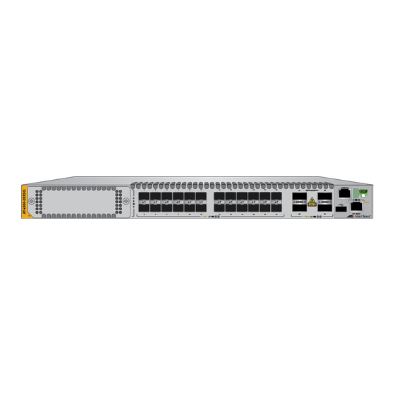
User Manuals: Allied Telesis AT-x950-28XSQ Switch
Manuals and User Guides for Allied Telesis AT-x950-28XSQ Switch. We have
2
Allied Telesis AT-x950-28XSQ Switch manuals available for free PDF download: Installation Manual
Allied Telesis AT-x950-28XSQ Installation Manual (190 pages)
Virtual Chassis Stacking. Advanced Layer 3+ Switch
Brand:
Allied Telesis
| Category:
Switch
| Size: 5.05 MB
Table of Contents
Table of Contents
5
Preface
13
Document Conventions
14
Contacting Allied Telesis
15
Chapter 1: Overview
17
AT-X950-28XSQ Switch
18
Figure 1: Front Panel of the AT-X950-28XSQ Switch
18
Figure 2: Rear Panel of the AT-X950-28XSQ Switch
18
Features
19
Hardware Features
19
XEM2 Series Ethernet Line Cards
19
Management Software and Interfaces
20
Management Methods
20
Management Panel
20
Power Supplies
20
Ports 1 to 24 for 1Gbps SFP or 10Gbps SFP+ Transceivers
21
SFP and SFP+ Transceivers
21
Leds
21
Figure 3: Link and Activity Leds for Ports 1 to 24
21
Table 1: Link and Activity Status Leds for Ports 1 to 24
22
Ports 25 to 37 for 40Gbps QSFP+ or 100Gbps QSFP28 Transceivers, or Breakout Cables
23
QSFP28 Transceivers
23
QSFP+ Transceivers
23
Breakout Cables
23
Figure 4: QSFP-4SFP10G-3CU or QSFP-4SFP10G-5CU Copper Breakout Cable
23
Leds
24
Figure 5: ET3-MPO08-4LC-5 or ET3-MPO08-4LC-10 Fiber Optic Breakout Cable
24
Figure 6: Leds for Ports 25 to 37
24
Table 2: Link and Activity Status Leds for 40Gbps QSFP+ or 100Gbps QSFP28 Transceivers
24
Port Numbering
25
Table 3: Link and Activity Status Leds for 10Gbps Breakout Cables
25
Table 4: Port Numbering for Ports 25 to 37
26
XEM2 Series Ethernet Line Cards
27
Figure 7: XEM2 Series Ethernet Line Cards
27
XEM2-12XT Line Card
28
RJ-45 Ports
28
Figure 8: XEM2-12XT Line Card
28
Table 5: Twisted Pair Ports on the XEM2-12XT Line Card
28
Leds
29
Table 6: Port Link and Activity Leds on the XEM2-12XT Line Card
29
XEM2-12XS Line Card
30
Transceivers
30
Leds
30
Figure 9: XEM2-12XS Line Card
30
Table 7: Port Link and Activity Leds on the XEM2-12XS Line Card
31
XEM2-4QS Line Card
32
Transceivers
32
Leds
32
Figure 10: XEM2-4QS Line Card
32
Table 8: Port Link and Activity Status Leds on the XEM2-4QS Line Card
32
XEM2-1CQ Line Card
34
Transceivers
34
Leds
34
Figure 11: XEM2-1CQ Line Card
34
Table 9: Port Link and Activity Status LED on the XEM2-1CQ Line Card
34
Management Panel
36
USB Port
36
Figure 12: Management Panel
36
NET MGMT Ethernet Management Port
37
Table 10: Twisted Pair Cable for the NET MGMT Port on the Management Panel
37
Console (RS-232) Port
38
Switch ID LED
38
Table 11: NET MGMT Port LED
38
Figure 13: Switch ID LED with the Eco-Friendly Mode Disabled
39
Figure 14: Switch ID LED with the Eco-Friendly Mode Enabled
39
Eco-Friendly Button
40
Optional Direct Attach Cables
41
Table 12: Optional Direct Attach Cables
41
AT-PWR600 Power Supply
42
Figure 15: AT-PWR600 Power Supply
42
Leds
43
Table 13: Leds on the AT-PWR600 Power Supply
43
AT-FAN05 Cooling Fan
44
Figure 16: AT-FAN05 Fan Module
44
Designating Ports in the Command Line Interface
45
Figure 17: PORT Parameter in the Command Line Interface
45
Figure 18: Slot Numbers for Port Numbering on Stand-Alone Switches
45
Table 14: PORT Parameter Format
45
Chapter 2: Virtual Chassis Stacking
47
Overview
48
Stacking Guidelines
49
Stack Trunks
50
10Gbps SFP+ Transceiver Slots
50
Figure 19: Base 10Gbps Transceiver Slots
50
Figure 20: Stack Trunk of Four 10Gbps Links of SFP+ Transceivers in the Base 10Gbps Slots
51
Figure 21: Invalid 10Gbps Trunk of Only One Link
52
Figure 22: Invalid 10Gbps Trunk with both Fiber Optic Transceivers and AT-SP10TW Direct Attach Cable
52
Figure 23: Invalid Trunk with both 10Gbps Transceivers and 40Gbps or 100Gbps Transceivers
52
40/100Gbps Transceiver Slots
53
Figure 24: Invalid Trunk of 10Gbps Transceivers in Base Slots and AT-XEM2-12XS Line Card
53
Figure 25: Base 40Gbps or 100Gbps Transceiver Slots
53
Figure 26: Stack Trunk of Four 40Gbps Links
54
Figure 27: Stack Trunk of Two 100Gbps Links
54
Figure 28: Invalid Trunk with Links Operating at 40Gbps and 100Gbps
54
Optional XEM2 Line Cards
55
Figure 29: Invalid Trunk with both Fiber Optic and Direct Attach Cables
55
Figure 30: Invalid Trunk with a 10Gbps Breakout Cable
55
Table 15: Maximum Number of Trunk Ports Per Switch on XEM2 Line Cards
55
Figure 31: Example of a Stack Trunk Using AT-XEM2-12XT Line Cards
56
Figure 32: Example of a Stack Trunk Using AT-XEM2-4QS Line Cards
56
Figure 33: Invalid Stack Trunk of Transceivers in AT-XEM2-12XS Line Card and 10Gbps Base Slots
57
Figure 34: Invalid 100Gbps Stack Trunk of Base 100Gbps Slots and AT-XEM2-1CQ Line Cards
57
Figure 35: Not Recommended Stack Trunk Using AT-XEM2-1CQ Line Cards
57
Additional Guidelines
58
Figure 36: Invalid Trunk with Intervening Network Devices
58
Master and Member Switches
59
Selection of the Master Switch
59
Switch ID Numbers
60
Optional Feature Licenses
61
Chapter 3: Beginning the Installation
63
Reviewing Safety Precautions
64
Installation Options
69
Figure 37: Installation Options
69
Choosing a Site for the Chassis
70
Unpacking the Switch
71
Figure 38: Removing Accessories
71
Figure 39: Removing the Shipping Partition
72
Figure 40: Lifting the Switch from the Shipping Box
73
Figure 41: Removing the Switch from the Shipping End-Caps and Protective Bag
73
Verifying the Accessory Kit
75
Figure 42: Accessory Kit
75
Unpacking the AT-PWR600 AC Power Supply
77
Figure 43: Removing the Power Cord and Documents from the AT-PWR600 AC Power Supply
77
Figure 44: Removing the Partition from the AT-PWR600 AC Power Supply Shipping Box
78
Figure 45: Removing the Power Supply from the Shipping Box
79
Figure 46: Removing the Power Supply from the Shipping End-Caps and Protective Bag
79
Chapter 4: Installing Power Supplies and Optional XEM2 Line Card
81
Installing PWR600 AC Power Supplies
82
Figure 47: Removing the Blank Power Supply Panel from Slot PSU B
83
Figure 48: Sliding the PWR600 AC Power Supply into the Switch
84
Figure 49: Seating the Power Supply on the Internal Connector
85
Installing an Optional XEM2 Ethernet Line Card
86
Figure 50: Removing the Blank Line Card Cover
86
Figure 51: Removing the Ethernet Line Card from the Anti-Static Bag
87
Figure 52: Sliding the Ethernet Line Card into the Slot
87
Figure 53: Seating the Ethernet Line Card in the Expansion Slot
88
Figure 54: Tightening the Two Captive Screws on the Ethernet Line Card
89
Chapter 5: Installing the Switch on a Table
91
Figure 55: Parts of the Bumper Feet
91
Figure 56: Holes for Bumper Feet
92
Figure 57: Inserting the Rivet Housing into the Bumper Foot
92
Figure 58: Placing the Bumper Foot on a Base Corner Hole
93
Figure 59: Inserting the Rivet into the Bumper Foot
93
Chapter 6: Installing the Switch in an Equipment Rack
95
Beginning the Installation
96
Required Items
96
Switch Orientations in the Equipment Rack
96
Figure 60: Bracket Holes on the Switch
96
Figure 61: AT-X950 Switch Orientations in an Equipment Rack
97
Removing the Bumper Feet
98
Figure 62: Removing the Bumper Feet
98
Installing the Switch
99
Figure 63: Attaching the Equipment Rack Brackets
100
Figure 64: Installing the Switch in an Equipment Rack
100
Chapter 7: Installing the Switch on a Wall
103
Switch Orientations on a Wall
104
Figure 65: Positions of the Switch on the Wall
104
Recommended Minimum Wall Area Dimensions
105
Figure 66: Minimum Wall Area Dimensions with the Front Panel on the Left
105
Figure 67: Minimum Wall Area Dimensions with the Front Panel on the Right
106
Plywood Base for a Wall with Wooden Studs
107
Figure 68: Switch on the Wall with a Plywood Base
107
Figure 69: Steps to Installing the Switch with a Plywood Base
108
Installation Guidelines
109
Tools and Material
109
Installing the Plywood Base
111
Installing the Switch on the Plywood Base
112
Figure 70: Installing the Brackets to the Switch for Wall Installation
112
Figure 71: Attaching the Switch to the Plywood Base
113
Installing the Switch on a Concrete Wall
115
Figure 72: Marking the Locations of the Bracket Holes on a Concrete Wall
116
Figure 73: Installing the Switch on a Concrete Wall
117
Chapter 8: Configuring Switches for Stacking
119
Introduction
120
Command Summary
121
Platform Portmode Interface
121
Stackport
122
Stack Enable
122
Stack Priority
122
Stack Renumber
123
Switch Provision
123
Powering on a Switch
124
Figure 74: Connecting the AC Power Cord
124
Figure 75: Securing the Power Cord with the Restraining Strap
125
Figure 76: Connecting the Power Cord to an AC Power Source
125
Starting a Local Management Session
127
Figure 77: Connecting the Management Cable to the Console RS-232 Port
127
Figure 78: User Exec Mode Prompt
128
Configuring the Master Switch
129
General Steps for the Master Switch
129
Configuring the Master Switch
130
Table 16: Configuring the Master Switch
130
Verifying the Master Switch
133
Table 17: Verifying the Master Switch
133
What to Do Next
134
Figure 79: Powering off the Switch
134
Configuring the Member Switch
136
General Steps for the Member Switch
136
Configuring the Member Switch - Part I
137
Table 18: Configuring the Member Switch - Part I
137
Configuring the Member Switch - Part II
139
Table 19: Configuring the Member Switch - Part II
140
Verifying the Member Switch
141
Table 20: Verifying the Configuration of the Member Switch
141
What to Do Next
142
Powering on the Stack
144
Verifying the Stack
145
Figure 80: SHOW STACK Command
145
Chapter 9: Cabling the Networking Ports
147
Cabling 1Gbps and 10Gbps Twister Pair Ports
148
Guidelines to Handling Twisted Pair or Fiber Optic Transceivers
149
Figure 81: Handle on 100Gbps Transceivers for XEM2-1CQ Line Cards
149
Installing Transceivers
150
Table 21: Transceivers for the Base Transceiver Slots
150
Figure 82: SP10T Transceivers
151
Table 22: Transceivers for the Optional XEM2 Ethernet Line Cards
151
Figure 83: Installing an SFP or SFP+ Transceiver
153
Figure 84: Installing 40Gbps Fiber Optic Transceivers in XEM2-4QS Line Cards
154
Figure 85: Installing 100Gbps QSFP28 Transceivers in Base Ports 25, 29, 33, 37
154
Figure 86: Installing 100Gbps QSFP28 Transceivers in XEM2-1CQ Line Cards
155
Installing Direct Attach Cables
156
Figure 87: Installing SP10TW Direct Attach Cables
156
Figure 88: Attaching QSFPCU Cables
157
Chapter 10: Replacing Modules
159
Replacing XEM2 Ethernet Line Cards
160
Figure 89: Loosening the Screws on the Ethernet Line Card
161
Figure 90: Disconnecting an Ethernet Line Card from the Switch
162
Figure 91: Sliding an Ethernet Line Card from the Switch
162
Figure 92: Placing the Ethernet Line Card in Its Anti-Static Bag
163
Figure 93: Installing the Line Card Blank Cover
163
Figure 94: Tightening the Two Screws on the Line Card Blank Panel
164
Replacing PWR600 AC Power Supplies
165
Figure 95: Disconnecting the AC Power Cord from the Power Source
165
Figure 96: Opening the Restraining Strap on the Power Supply
166
Figure 97: Disconnecting the Power Cord from the Power Supply
166
Figure 98: Removing the Power Supply
167
Figure 99: Removing a Power Supply
168
Figure 100: Installing the Blank Power Supply Cover
169
Replacing FAN05 Modules
170
Removing Fan Modules
170
Figure 101: Loosening the Screws on the Fan Module
170
Figure 102: Disconnecting the FAN05 Module from the Switch
171
Figure 103: Sliding the Fan Module from the Switch
171
Installing Fan Modules
172
Figure 104: Removing the Fan Module from the Shipping Container
172
Figure 105: Aligning the FAN05 Module in the Switch Slot
173
Figure 106: Seating the FAN05 Module on the Internal Connector
173
Figure 107: Tightening the Two Captive Screws on the FAN05 Module
174
Chapter 11: Troubleshooting
175
Appendix A: Technical Specifications
181
Physical Specifications
182
Table 23: Product Dimensions
182
Table 24: Product Weights
182
Table 25: Ventilation Requirements
183
Environmental Specifications
184
Table 26: Environmental Specifications
184
Power Specifications
185
Table 27: Maximum Power Consumptions (Watts)
185
Table 28: Typical Power Savings in Eco-Friendly Mode (Watts)
185
Table 29: Input Voltages
185
Table 30: Maximum Power Supply Efficiency (Based on 100V Input Voltage)
186
Table 31: Heat Dissipations (British Thermal Units/Hour)
186
Certifications
187
Table 32: Product Certifications
187
RJ-45 Twisted Pair Port Pinouts on the AT-XEM2-12XT Card
188
Figure 108: Pin Layout (Front View) of the 1Gbps or 10Gbps Ports on the AT-XEM2-12XT Line Card
188
Table 33: Pin Signals for 1Gbps or 10Gbps
188
Style Serial Console Port Pinouts
189
Table 34: RJ-45 Style Serial Console Port Pin Signals
189
Advertisement
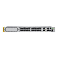
Allied Telesis AT-x950-28XSQ Installation Manual (166 pages)
Advanced Layer 3+ Stand-alone Switches
Brand:
Allied Telesis
| Category:
Switch
| Size: 4.39 MB
Table of Contents
Table of Contents
5
Preface
11
Document Conventions
12
Contacting Allied Telesis
13
Chapter 1: Overview
15
X950 Switches
16
Figure 1: Front Panels of the X950 Switches
16
Figure 2: Rear Panel of the X950 Switches
17
Features
18
Hardware Features
18
XEM2 Ethernet Line Cards
18
Management Software and Interfaces
19
Management Methods
19
Management Panel
19
Power Supplies
19
Ports 1 to 24 on the AT-X950-28XSQ Switch
20
SFP and SFP+ Transceivers
20
Leds
21
Figure 3: Link and Activity Leds for Ports 1 to 24
21
Table 1: Link and Activity Status Leds for Ports 1 to 24
21
Ports 1 to 24 on the AT-X950-28Xtqm Switch
22
Cable Requirements
22
Table 2: Twisted Pair Ports 1 to 24 on the AT-X950-28Xtqm Switch
22
Leds
23
Figure 4: Link and Activity Leds for Ports 1 to 24 on the AT-X950-28Xtqm Switch
23
Table 3: Link and Activity Leds for Ports 1 to 24 on the AT-X950-28Xtqm Switch
23
Ports 25 to 37
24
QSFP28 Transceivers
24
QSFP+ Transceivers
24
Breakout Cables
24
Figure 5: QSFP-4SFP10G-3CU and QSFP-4SFP10G-5CU Copper Breakout Cables
24
Leds
25
Figure 6: ET3-MPO08-4LC-5 and ET3-MPO08-4LC-10 Fiber Optic Breakout Cables
25
Figure 7: Leds for Ports 25 to 37
25
Table 4: Link and Activity Status Leds for 40Gbps QSFP+ or 100Gbps QSFP28 Transceivers
25
Port Numbering
26
Table 5: Link and Activity Status Leds for 10Gbps Breakout Cables
26
Table 6: Port Numbering for Ports 25 to 37
27
XEM2 Ethernet Line Cards
28
Figure 8: XEM2 Ethernet Line Cards
28
Table 7: XEM2 Ethernet Line Cards
28
AT-XEM2-12XT Line Card
30
RJ-45 Ports
30
Figure 9: AT-XEM2-12XT Line Card
30
Table 8: Twisted Pair Ports on the AT-XEM2-12XT Line Card
30
Leds
31
Table 9: Port Link and Activity Leds on the AT-XEM2-12XT Line Card
31
AT-XEM2-12Xtm Line Card
32
Figure 10: AT-XEM2-12Xtm Line Card
32
Table 10: Twisted Pair Ports on the AT-XEM2-12Xtm Line Card
32
Table 11: Link and Activity Leds on the AT-XEM2-12Xtm Line Card
33
AT-XEM2-12XS Line Card
34
Transceivers
34
Figure 11: AT-XEM2-12XS Line Card
34
Leds
35
Table 12: Port Link and Activity Leds on the AT-XEM2-12XS Line Card
35
AT-XEM2-4QS Line Card
36
Transceivers
36
Leds
36
Figure 12: AT-XEM2-4QS Line Card
36
Table 13: Port Link and Activity Status Leds on the AT-XEM2-4QS Line Card
37
Table 14: Link and Activity Status Leds for 10Gbps Breakout Cables
37
AT-XEM2-1CQ Line Card
38
Transceivers
38
Leds
38
Figure 13: AT-XEM2-1CQ Line Card
38
Table 15: Port Link and Activity Status LED on the AT-XEM2-1CQ Line Card
39
Management Panel
40
USB Port
40
Figure 14: Management Panel
40
NET MGMT Ethernet Management Port
41
Table 16: NET MGMT Port LED
41
Console (RS-232) Port
42
Switch ID LED
42
Figure 15: Switch ID LED with the Eco-Friendly Mode Disabled
43
Figure 16: Switch ID LED with the Eco-Friendly Mode Enabled
43
Eco-Friendly Button
44
Optional Direct Attach Cables
45
Table 17: Optional Direct Attach Cables
45
AT-PWR600 Power Supply
46
Figure 17: AT-PWR600 Power Supply
46
Leds
47
Table 18: Leds on the AT-PWR600 Power Supply
47
AT-FAN05 Cooling Fan
48
Figure 18: AT-FAN05 Fan Module
48
Designating Ports in the Command Line Interface
49
Figure 19: PORT Parameter in the Command Line Interface
49
Table 19: PORT Parameter Format
49
Figure 20: Slot Numbers for Port Numbering on Stand-Alone Switches
50
Software and Hardware Releases
51
Table 20: Software and Hardware Releases
51
Chapter 2: Beginning the Installation
53
Reviewing Safety Precautions
54
Installation Options
59
Figure 21: Installation Options
59
Choosing a Site for the Chassis
60
Unpacking the Switch
61
Figure 22: Removing Accessories
61
Figure 23: Removing the Shipping Box Partition
62
Figure 24: Lifting the Switch from the Shipping Box
63
Figure 25: Removing the Switch from the Shipping End-Caps and Protective Bag
63
Verifying the Accessory Kit
65
Figure 26: Accessory Kit
65
Unpacking the AT-PWR600 AC Power Supply
67
Figure 27: Removing the Power Cord and Documents from the AT-PWR600 AC Power Supply
67
Figure 28: Removing the Partition from the AT-PWR600 AC Power Supply Shipping Box
68
Figure 29: Removing the Power Supply from the Shipping Box
69
Figure 30: Removing the Power Supply from the Shipping End-Caps and Protective Bag
69
Chapter 3: Installing Power Supplies and Optional XEM2 Line Card
71
Installing AT-PWR600 AC Power Supplies
72
Figure 31: Removing the Blank Power Supply Panel from Slot PSU B
73
Figure 32: Sliding the AT-PWR600 AC Power Supply into the Chassis
74
Figure 33: Seating the Power Supply on the Internal Connector
75
Installing an Optional XEM2 Ethernet Line Card
76
Figure 34: Removing the Blank Line Card Cover
76
Figure 35: Removing the Ethernet Line Card from the Anti-Static Bag
77
Figure 36: Sliding the Ethernet Line Card into the Slot
77
Figure 37: Seating the Ethernet Line Card in the Expansion Slot
78
Figure 38: Tightening the Two Captive Screws on the Ethernet Line Card
79
Chapter 4: Installing the Switch on a Table
81
Figure 39: Parts of the Bumper Feet
81
Figure 40: Holes for Bumper Feet
82
Figure 41: Inserting the Rivet Housing into the Bumper Foot
82
Figure 42: Placing the Bumper Foot on a Base Corner Hole
83
Figure 43: Inserting the Rivet into the Bumper Foot
83
Chapter 5: Installing the Switch in an Equipment Rack
85
Beginning the Installation
86
Required Items
86
Switch Orientations in the Equipment Rack
86
Figure 44: Bracket Holes on the Switch
86
Figure 45: Switch Orientations in an Equipment Rack
87
Removing the Bumper Feet
88
Figure 46: Removing the Bumper Feet
88
Installing the Switch
89
Figure 47: Attaching the Equipment Rack Brackets
90
Figure 48: Installing the Switch in an Equipment Rack
90
Chapter 6: Installing the Switch on a Wall
93
Switch Orientations on a Wall
94
Figure 49: Positions of the Switch on the Wall
94
Recommended Minimum Wall Area Dimensions
95
Figure 50: Minimum Wall Area Dimensions with the Front Panel on the Left
95
Figure 51: Minimum Wall Area Dimensions with the Front Panel on the Right
96
Plywood Base for a Wall with Wooden Studs
97
Figure 52: Switch on the Wall with a Plywood Base
97
Figure 53: Steps to Installing the Switch with a Plywood Base
98
Installation Guidelines
99
Tools and Material
99
Installing the Plywood Base
101
Installing the Switch on the Plywood Base
102
Figure 54: Installing the Brackets to the Switch for Wall Installation
102
Figure 55: Attaching the Switch to the Plywood Base
104
Installing the Switch on a Concrete Wall
105
Figure 56: Marking the Locations of the Bracket Holes on a Concrete Wall
106
Figure 57: Installing the Switch on a Concrete Wall
107
Chapter 7: Verifying and Configuring the Switch
109
Powering on the Switch
110
Figure 58: Connecting the AC Power Cord
111
Figure 59: Securing the Power Cord with the Restraining Strap
111
Figure 60: Connecting the Power Cord to an AC Power Source
112
Starting a Local Management Session
113
Figure 61: Connecting the Management Cable to the Console RS-232 Port
113
Figure 62: User Exec Mode Prompt
114
Verifying the Switch with Alliedware Plus Commands
115
Disabling Vcstack
116
Figure 63: SHOW STACK Command
116
Figure 64: Moving to the Global Configuration Mode
117
Figure 65: Confirmation Prompt for the no STACK ENABLE Command
117
Figure 66: Returning to the Privileged Exec Mode
117
Figure 67: Saving the Changes with the WRITE Command
118
Configuring Ports 25 to 37
119
Saving Your Changes and Rebooting the Switch
121
Figure 68: Returning to the Privileged Exec Mode
121
Figure 69: Saving the Changes with the WRITE Command
121
Chapter 8: Cabling the Networking Ports
123
Cabling Twisted Pair Ports
124
Guidelines to Handling Twisted Pair or Fiber Optic Transceivers
125
Figure 70: Handle on 100Gbps Transceivers for AT-XEM2-1CQ Line Cards
125
Installing Transceivers
126
Table 21: Transceivers for the Base Transceiver Slots
126
Figure 71: SP10T Transceivers
127
Table 22: Transceivers for the Optional XEM2 Ethernet Line Cards
127
Figure 72: Installing an SFP or SFP+ Transceiver
129
Figure 73: Installing 40Gbps Fiber Optic Transceivers in AT-XEM2-4QS Line Cards
130
Figure 74: Installing 100Gbps QSFP28 Transceivers in Base Ports 25 to 37
130
Figure 75: Installing 100Gbps QSFP28 Transceivers in AT-XEM2-1CQ Line Cards
131
Installing Direct Attach Cables
132
Figure 76: Installing SP10TW Direct Attach Cables
132
Figure 77: Attaching QSFPCU Cables
133
Chapter 9: Replacing Modules
135
Replacing XEM2 Ethernet Line Cards
136
Figure 78: Loosening the Screws on the Ethernet Line Card
137
Figure 79: Disconnecting an Ethernet Line Card from the Switch
138
Figure 80: Sliding an Ethernet Line Card from the Switch
138
Figure 81: Placing the Ethernet Line Card in Its Anti-Static Bag
139
Figure 82: Installing the Line Card Blank Cover
139
Figure 83: Tightening the Two Screws on the Line Card Blank Panel
140
Replacing AT-PWR600 AC Power Supplies
141
Figure 84: Disconnecting the AC Power Cord from the Power Source
141
Figure 85: Opening the Restraining Strap on the Power Supply
142
Figure 86: Disconnecting the Power Cord from the Power Supply
142
Figure 87: Removing the Power Supply
143
Figure 88: Removing a Power Supply
144
Figure 89: Installing the Blank Power Supply Cover
145
Replacing FAN05 Modules
146
Removing Fan Modules
146
Figure 90: Loosening the Screws on the Fan Module
146
Figure 91: Disconnecting the FAN05 Module from the Switch
147
Figure 92: Sliding the Fan Module from the Switch
147
Installing Fan Modules
148
Figure 93: Removing the Fan Module from the Shipping Container
148
Figure 94: Aligning the FAN05 Module in the Switch Slot
149
Figure 95: Seating the FAN05 Module on the Internal Connector
149
Figure 96: Tightening the Two Captive Screws on the FAN05 Module
150
Chapter 10: Troubleshooting
151
Appendix A: Technical Specifications
157
Physical Specifications
158
Table 23: Product Dimensions
158
Table 24: Product Weights
158
Table 25: Ventilation Requirements
159
Environmental Specifications
160
Table 26: Environmental Specifications
160
Power Specifications
161
Table 27: Maximum Power Consumptions (Watts)
161
Table 28: Typical Power Savings in Eco-Friendly Mode (Watts)
161
Table 29: Input Voltages
162
Table 30: Maximum Power Supply Efficiency (Based on 100V Input Voltage)
162
Table 31: Heat Dissipations (British Thermal Units/Hour)
162
Certifications
164
Table 32: Product Certifications
164
Twisted Pair Port Pinouts on AT-XEM2-12XT and AT-XEM2-12Xtm Cards
165
Twisted Pair Port Pinouts on AT-XEM2-12XT and AT-XEM2- 12Xtm Cards
165
Figure 97: Pin Layout (Front View) of the Ports on the AT-XEM2-12XT and AT-XEM2-12Xtm Line Cards
165
Table 33: Port Pin Signals on the AT-XEM2-12XT and AT-XEM2-12Xtm Line Cards
165
RJ-45 Style Serial Console Port Pinouts
166
Table 34: RJ-45 Style Serial Console Port Pin Signals
166
Advertisement
Related Products
Allied Telesis AT-x950-28XTQm
Allied Telesis AT-x900-12XT/S
Allied Telesis AT-x900-48FE
Allied Telesis AT-x900-48FS
Allied Telesis AT-X900-24XS
Allied Telesis AT-X900-24XT
Allied Telesis AT-X900-24XT-N
Allied Telesis AT-x900-48FE-N
Allied Telesis Switchblade AT-x900-12
Allied Telesis Switchblade AT-x900-24
Allied Telesis Categories
Switch
Network Router
Media Converter
Network Hardware
Wireless Access Point
More Allied Telesis Manuals
Login
Sign In
OR
Sign in with Facebook
Sign in with Google
Upload manual
Upload from disk
Upload from URL