Sign In
Upload
Manuals
Brands
Allied Telesis Manuals
Switch
AT-IE300-12GT
User Manuals: Allied Telesis AT-IE300-12GT 3 Switch
Manuals and User Guides for Allied Telesis AT-IE300-12GT 3 Switch. We have
1
Allied Telesis AT-IE300-12GT 3 Switch manual available for free PDF download: Installation Manual
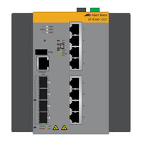
Allied Telesis AT-IE300-12GT Installation Manual (126 pages)
IE300 Series. Industrial Ethernet Switches
Brand:
Allied Telesis
| Category:
Switch
| Size: 3.59 MB
Table of Contents
Table of Contents
7
Preface
13
Safety Symbols Used in this Document
14
Contacting Allied Telesis
15
Overview
17
Hardware Components
18
Figure 1: Front Panel of the AT-IE300-12GT Switch
18
Figure 2: Front Panel of the AT-IE300-12GP Switch
19
Figure 3: Top Panel
19
Figure 4: Back Panel Features
20
Features
21
Twisted Pair Ports
21
Power over Ethernet
21
SFP Slots
21
Leds
22
Alarm Connectors
22
MAC Address Tables
22
Management Software
22
Management Methods
22
Installation Options
22
Additional Features
22
10/100/1000Base-T Twisted Pair Ports
24
Connector Type
24
Speed
24
Duplex Mode
24
Maximum Distance
24
Cable Requirements
24
Automatic MDIX Detection
25
Port Pinouts
25
Table 1: Twisted Pair Cable for the AT-IE300-12GT Switch
25
Power over Ethernet
26
Poe Versions
26
Ethernet Cabling for Poe Devices
26
Table 2: Maximum Power Levels
26
Powered Device Classes for Poe and Poe
27
Table 3: Twisted Pair Cable for Powered Devices on the AT-IE300-12GP Switch
27
Table 4: Poe and Poe+ Powered Device Classes
27
Power Delivery with Alternatives a and B
28
Poe Budget
30
Port Prioritization
30
SFP Slots
32
Table 5: Maximum Installation Site Temperatures Versus SFP Temperature Ratings
32
Console Port
33
USB Port
34
Reset Button
34
Ground Screw
35
PWR 1 and PWR 2 DC Power Connectors
35
Alarm in Connector
36
Figure 5: Example 1 of the Alarm in (ALM IN) Connector
37
Figure 6: Example 2 of the Alarm in (ALM IN) Connector
38
Alarm out Connector
39
DIN Rail Bracket
40
Screw Holes for Wall Brackets
40
Figure 7: Example of the Alarm out Port
40
Leds
41
Status Leds
41
Table 6: Status Leds
41
Twisted Pair Port Leds
42
Figure 8: Twisted Pair Port Leds on the AT-IE300-12GT Switch
42
Figure 9: Twisted Pair Ports on the AT-IE300-12GP Switch
43
Table 7: Twisted Pair Port Leds on the AT-IE300-12GT Switch
43
SFP Slot Leds
44
Table 8: Twisted Pair Port Leds on the AT-IE300-12GP Switch
44
Table 9: SFP Slot LED
44
Poe Status Leds
45
Table 10: Poe Status Leds
45
Power Supplies
48
Optional Drip Guard
49
Figure 10: Optional Drip Guard
49
Beginning the Installation
51
Reviewing Safety Precautions
52
Safety Precautions When Working with Electricity
56
Reviewing Site Requirements
57
Table 11: Ground Resistivity Recommendations
58
Verifying the Package Contents
59
Figure 11: Pre-Installed Components on the Front Panel
59
Figure 12: Pre-Installed Components on the Top Panel
60
Figure 13: Pre-Installed Component on the Back Panel
61
Figure 14: Components in the Accessory Kit
62
Installing the Switch
63
Installing the Switch on a DIN Rail
64
Figure 15: Orientation of the Switch on a DIN Rail
64
Figure 16: Installing the Switch on a DIN Rail - 1
65
Figure 17: Installing the Switch on a DIN Rail - 2
65
Figure 18: Verifying the DIN Rail Installation
66
Installing the Switch on a Wooden Wall
67
Figure 19: Switch on the Wall with a Plywood Base
67
Figure 20: Steps to Installing the Switch with a Plywood Base
68
Installing the Plywood Base
68
Tools and Material
68
Figure 21: Installing the Wall Brackets on the Switch
69
Installing the Switch on the Plywood Base
69
Figure 22: Attaching the Switch to the Plywood Base
70
Installing the Switch on a Concrete Wall
71
Figure 23: Marking the Locations of the Bracket Holes on a Concrete Wall
72
Figure 24: Installing the Switch on a Concrete Wall
73
Cabling the Ports
75
Cabling the Twisted Pair Ports
76
Installing SFP Transceivers
78
Figure 25: Removing the Dust Plug from an SFP Slot
79
Figure 26: Installing an SFP Transceiver
79
Figure 27: Removing the Dust Cover from an SFP Transceiver
80
Figure 28: Verifying the Position of the SFP Handle
80
Figure 29: Connecting a Fiber Optic Cable to an SFP Transceiver
81
Powering on the Switch
83
Connecting the Grounding Wire
84
Figure 30: Stripping the Grounding Wire
84
Figure 31: Loosening the Grounding Screw
85
Figure 32: Wrapping the Grounding Wire Around the Grounding Screw
85
Figure 33: Securing the Grounding Wire to the Switch
86
Wiring the ALM in and ALM out Connectors
87
Figure 34: Polarity Legend for the Alarm Connectors
88
Figure 35: Stripping an Alarm Wire
88
Figure 36: Wrapping the Wire Strands
89
Figure 37: Removing an Alarm Connector
89
Figure 38: Loosening the Wire Retaining Screws on an Alarm Connector
89
Figure 39: Inserting the Wires into the DC Cable Connector
90
Figure 40: Inserting the DC Connector into the Alarm Connector
91
Preparing the DC Power Cables
92
Figure 41: Pin Signals Legends for the PWR 1 and PWR 2 Connectors
92
Figure 42: Stripping a Power Cable Wire
93
Figure 43: Removing the PWR 1 - PWR 2 Cable Connector
93
Figure 44: Loosening the Wire Retaining Screws on the PWR 1 - PWR 2 Cable Connector
94
Figure 45: Inserting the Wires into the PWR 1 - PWR 2 Cable Connector
94
Figure 46: Verifying the Wire Installation
95
Powering on the Switch
96
Figure 47: Connecting the Power Cable to the PWR 1 - PWR 2 Connector
96
Verifying Switch Operations
97
Monitoring the Initialization Process
98
Figure 48: Initialization Messages
98
Figure 49: Initialization Messages (Continued)
99
Starting a Local Management Session
100
Verifying the AT-IE300-12GP Switch
102
Verifying the Poe Budget
102
Configuring Alternatives a and B
103
Configuring the Provisioned Poe Budget
104
Installing the Optional Drip Guard
107
Figure 50: Installing the Optional Drip Guard
107
Figure 51: Securing the Drip Guard
108
Troubleshooting
109
PWR 1 and PWR 2 Leds
110
Twisted Pair Ports
111
SFP Slots
113
Power over Ethernet
114
Technical Specifications
117
Physical Specifications
118
Table 12: Product Dimensions
118
Table 13: Product Weights
118
Table 14: Ventilation Requirements for Cabinet Installation
118
Table 15: Minimum Cabinet Dimensions
119
Environmental Specifications
120
Table 16: Environmental Specifications
120
Table 17: Ingress Protection
120
Power Specifications
121
Table 18: Maximum Power Consumptions
121
Table 19: Input Power Specifications
121
Table 20: Heat Dissipation (British Thermal Units/Hour)
121
Certifications
122
Table 21: Regulatory Approvals
122
RJ-45 Twisted Pair Port Pinouts
123
Figure 52: RJ-45 Port Pin Layout (Front View)
123
Table 22: Pin Signals for 10 and 100 Mbps
123
Table 23: Pin Signals for 1000 Mbps
123
RJ-45 Style Serial Console Port Pinouts
125
Figure 53: Console Port Pin Layout (Front View)
125
Table 24: RJ-45 Style Console Port Pin Signals
125
PWR 1 and PWR 2 DC Power Connectors
126
Table 25: PWR 1 and PWR 2 DC Connector Pin Signals on the AT-IE300-12GT Switch
126
Table 26: PWR 1 and PWR 2 DC Connector Pin Signals on the AT-IE300-12GP Switch
126
Advertisement
Advertisement
Related Products
Allied Telesis AT-IE300-12GP
Allied Telesis AT-IE200-6GT-80
Allied Telesis AT-IE200-6FT-80
Allied Telesis AT-IE200-6FP-80
Allied Telesis AT-IE200-6GP-80
Allied Telesis AT-IE210L-10GP
Allied Telesis AT-IE200-6FP
Allied Telesis AT-IE200-6GT
Allied Telesis AT-IE200-6GP
Allied Telesis AT-IE510-28GSX
Allied Telesis Categories
Switch
Network Router
Media Converter
Network Hardware
Wireless Access Point
More Allied Telesis Manuals
Login
Sign In
OR
Sign in with Facebook
Sign in with Google
Upload manual
Upload from disk
Upload from URL