Sign In
Upload
Manuals
Brands
Allen-Bradley Manuals
Controller
controllogix 1756-L61
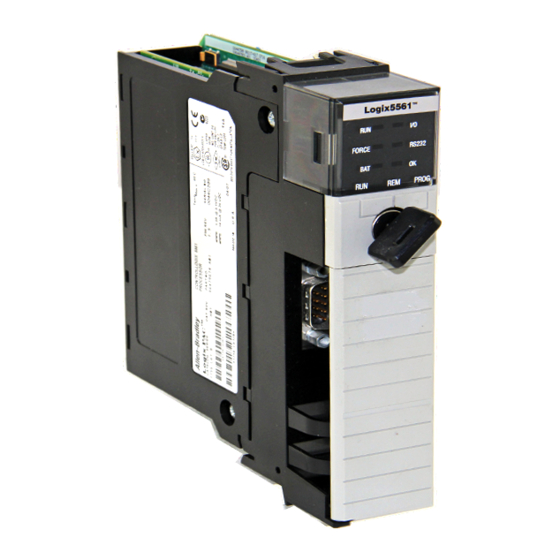
Allen-Bradley controllogix 1756-L61 Manuals
Manuals and User Guides for Allen-Bradley controllogix 1756-L61. We have
7
Allen-Bradley controllogix 1756-L61 manuals available for free PDF download: User Manual, Programming Manual, Application Book
Allen-Bradley controllogix 1756-L61 User Manual (238 pages)
ControlLogix System
Brand:
Allen-Bradley
| Category:
Controller
| Size: 6.59 MB
Table of Contents
Table of Contents
5
Controllogix Controllers Overview
13
Traditional Controllogix Controllers
13
Redundant Controllogix Controllers
14
Extreme Environment Controllogix Controllers
14
Preface
13
Before You Begin
14
Required Software
14
Additional Resources
15
Chapter 1
19
Environment and Enclosure
19
Install the 1756-L7X Controller
19
Compactflash/Sd Card Capability
20
European Hazardous Location Approval
20
Prevent Electrostatic Discharge
20
Removal and Insertion under Power (RIUP)
20
North American Hazardous Location Approval
21
USB Port
21
1756-L7X Controller Parts
22
Parts Included with the 1756-L7X Controller
22
Parts Available for Use with the 1756-L7X Controller
23
Before You Begin
22
1756-L7X Controller Installation
23
Insert the Controller into the Chassis
23
Insert the Key
24
Remove the SD Card
25
Install the SD Card
26
Uninstall the ESM
27
Install the ESM
30
Chapter 2 Precautions
31
Environment and Enclosure
31
Programmable Electronic Systems (PES)
32
Preventing Electrostatic Discharge
32
Removing Module While under Power (RIUP)
32
European Hazardous Location Approval
32
USB Port
33
North American Hazardous Location Approval
33
Lithium Batteries
34
Install the 1756-L6X Controller
31
1756-L6X Controller Parts
34
Parts Not Included with the 1756-L6X Controller
35
Before You Begin
34
1756-L6X Controller Installation
36
Compactflash Card Installation and Removal
36
Battery Connection and Replacement
38
Insert the Controller into the Chassis
41
Remove the Controller from the Chassis
42
Chapter 3 Make Connections
45
1756-L7X Connection Options
45
1756-L6X Connection Options
46
Start Using the Controller
45
Connect to the 1756-L7X Controller
47
Set up the USB Driver
48
Connect to the 1756-L6X Controller
50
Configure the Serial Driver
51
Upgrade Controller Firmware
53
Determine Required Controller Firmware
54
Obtain Controller Firmware
55
Use Controlflash Utility to Upgrade Firmware
55
Use Autoflash to Upgrade Firmware
58
Set the Communication Path
60
Go Online with the Controller
61
Download to the Controller
62
Use the Who Active Dialog Box to Download
62
Use the Controller Status Menu to Download
63
Upload from the Controller
63
Use the Who Active Dialog Box to Upload
63
Use the Controller Status Menu to Upload
64
Choose the Controller Operation Mode
65
Use the Mode Switch to Change the Operation Mode
65
Use Rslogix 5000 Software to Change the Operation Mode
67
Load or Store to the Memory Card
68
Store to the Memory Card
68
Load from the Memory Card
72
Other Memory Card Tasks
74
Use Controllogix Energy Storage Modules (Esms)
74
Save the Program to On-Board NVS Memory
75
Clear the Program from On-Board NVS Memory
76
Estimate the ESM Support of the Wallclocktime
76
(1756-L6X Controllers Only)
77
Check the Battery Status
78
1756-BA1 or 1756-BATA Battery Life
78
1756-BATM Battery Module and Battery Life
79
Estimate 1756-BA2 Battery Life
80
Estimate 1756-BA2 Battery Life after Warnings
81
Battery Storage and Disposal
82
Maintain the Battery
77
Additional Resources
83
Rockwell Automation Publication 1756-UM001M-EN-P - February
84
Chapter 4 Configuration Options
85
The Controllogix System
85
Design a Controllogix System
88
Controllogix Controller Features
89
System, Communication, and Programming Features
89
Memory Options
90
Additional Resources
91
Chapter 5
93
Communication Networks
93
Networks Available
93
Ethernet/Ip Network Communication
94
Controllogix Ethernet/Ip Module Features
94
Controllogix Ethernet/Ip Communication Modules
95
Software for Ethernet/Ip Networks
96
Connections over an Ethernet/Ip Network
96
Double Data Rate (DDR) Backplane Communication
97
Controlnet Network Communication
97
Controllogix Controlnet Module Features
99
Controllogix Controlnet Modules
99
Software for Controlnet Networks
99
Connections over a Controlnet Network
100
Devicenet Network Communication
100
Controllogix Devicenet Module Features
101
Controllogix Devicenet Bridge Module and Linking Devices
102
Software for Devicenet Networks
102
Connections over Devicenet Networks
102
Controllogix Devicenet Module Memory
102
Data Highway Plus (DH+) Network Communication
103
Communicate over a DH+ Network
104
Universal Remote I/O (RIO) Communication
104
Communicate over a Universal Remote I/O Network
106
Foundation Fieldbus Communication
107
HART Communication
108
Additional Resources
109
1756-L6X Controller Serial Port
111
Chapter 6 Controllogix Chassis Serial Communication Options
112
Communication with Serial Devices
112
DF1 Master Protocol
112
DF1 Point to Point Protocol
113
DF1 Radio Modem Protocol
113
DF1 Radio Modem Advantages
114
DF1 Radio Modem Limitations
115
DF1 Radio Modem Protocol Parameters
116
DF1 Slave Protocol
116
DH-485 Protocol
117
ASCII Protocol
119
Configure the 1756-L6X Controller for Serial Communication
119
Broadcast Messages over a Serial Port
121
Configure Controller Serial Port Properties
122
Program the Message Instruction
123
Additional Resources
124
Modbus Support
124
Chapter 7 Produce and Consume (Interlock) Data
125
Connection Requirements of a Produced or Consumed Tag
126
Connection Overview
125
Send and Receive Messages
127
Determine Whether to Cache Message Connections
128
Calculate Connection Use
129
Local Connections
129
Remote Connections
130
Connections Example
131
Additional Resources
132
Chapter 8
133
Selecting Controllogix I/O Modules
133
Local I/O Modules
134
Add Local I/O to the I/O Configuration
134
Remote I/O Modules
136
Add Remote I/O to the I/O Configuration
137
Distributed I/O
140
Add Distributed I/O to the I/O Configuration
141
Reconfigure an I/O Module
143
Reconfigure an I/O Module Via the Module Properties
143
Reconfigure an I/O Module Via a Message Instruction
144
Add to the I/O Configuration While Online
144
Modules and Devices that Can be Added While Online
145
Online Additions - Controlnet Considerations
147
Rockwell Automation Publication 1756-UM001M-EN-P - February
148
Online Additions - Ethernet/Ip Considerations
150
Determine When Data Is Updated
151
Additional Resources
152
Chapter 9
153
Develop Motion Applications
153
Motion Control Options
153
Motion Overview
153
Obtain Axis Information
154
Program Motion Control
154
Additional Resources
157
Chapter 10
159
Develop Applications
159
Elements of a Control Application
159
Tasks
160
Task Priority
163
Programs
163
Scheduled and Unscheduled Programs
165
Routines
166
Tags
167
Programming Languages
168
Add-On Instructions
169
Monitoring Controller Status
170
Monitoring I/O Connections
171
Determine if I/O Communication Has Timed out
171
Determine if I/O Communication to a Specific I/O Module Has
172
Timed out
172
Interrupt the Execution of Logic and Execute the Fault Handler
172
System Overhead Time Slice
173
Configure the System Overhead Time Slice
174
Sample Controller Projects
175
Additional Resources
176
Chapter 11
177
Phasemanager Overview
177
Using the Phasemanager Tool
177
Minimum System Requirements
179
State Model Overview
180
How Equipment Changes States
181
Manually Change States
182
Phasemanager Tool Versus Other State Models
182
Additional Resources
183
Equipment Phase Instructions
183
Chapter 12
185
Controllogix Redundancy Overview
185
System Requirements
187
System Considerations
188
Enhanced Versus Standard Redundancy
189
Build a Redundant System
190
Controlnet Considerations in Redundant Systems
190
Ethernet/Ip Considerations in Redundant Systems
191
IP Address Swapping
191
Redundancy and Scan Time
192
Additional Resources
193
Chapter 13 Introduction to SIL
195
Programming and Debugging Tool (PADT)
195
Advertisement
Allen-Bradley controllogix 1756-L61 User Manual (212 pages)
ControlLogix System
Brand:
Allen-Bradley
| Category:
Control Systems
| Size: 7.51 MB
Table of Contents
Table of Contents
5
Controllogix Controllers Overview
11
Standard Controllogix Controllers
12
Redundant Controllogix Controllers
13
Extreme Environment Controllogix Controllers
13
Preface
11
Studio 5000 Environment
11
Before You Begin
14
Required Software
14
Additional Resources
15
Install the 1756-L7X Controller
20
Chapter 1
21
Before You Begin
21
1756-L7X Controller Parts
21
Parts Included with the 1756-L7X Controller
21
Parts Available for Use with the 1756-L7X Controller
22
1756-L7X Controller Installation
22
Insert the Controller into the Chassis
23
Insert the Key
24
Install the SD Card
25
Remove the SD Card
26
Install the ESM
28
Uninstall the ESM
29
Install the 1756-L6X Controller
34
Chapter 2
35
Before You Begin
35
1756-L6X Controller Parts
35
Parts Not Included with the 1756-L6X Controller
35
1756-L6X Controller Installation
36
Compactflash Card Installation and Removal
36
Battery Connection and Replacement
39
Insert the Controller into the Chassis
42
Remove the Controller from the Chassis
44
Chapter 3 Make Connections
45
1756-L7X Connection Options
45
1756-L6X Connection Options
46
Connect to the 1756-L7X Controller
46
Configure the USB Driver
47
Connect to the 1756-L6X Controller
49
Configure the Serial Driver
50
Upgrade Controller Firmware
52
Determine Required Controller Firmware
52
Obtain Controller Firmware
53
Use Controlflash Software to Upgrade Firmware
53
Use Autoflash to Upgrade Firmware
56
Set the Communication Path
58
Go Online with the Controller
58
Download to the Controller
59
Use the Who Active Dialog Box to Download
59
Use the Controller Status Menu to Download
60
Upload from the Controller
60
Use the Who Active Dialog Box to Upload
60
Use the Controller Status Menu to Upload
61
Choose the Controller Operation Mode
62
Use the Mode Switch to Change the Operation Mode
62
Use Logix Designer to Change the Operation Mode
64
Load or Store to the Memory Card
65
Store to the Memory Card
65
Load from the Memory Card
68
Other Memory Card Tasks
70
Use Controllogix Energy Storage Modules (Esms)
70
Save the Program to On-Board NVS Memory
71
Clear the Program from On-Board NVS Memory
71
Estimate the ESM Support of the Wallclocktime
72
Maintain the Battery (Only 1756-L6X Controllers)
72
Check the Battery Status
72
1756-BA1 or 1756-BATA Battery Life
73
1756-BATM Battery Module and Battery Life
74
Estimate 1756-BA2 Battery Life
75
Estimate 1756-BA2 Battery Life after Warnings
76
Battery Storage and Disposal
77
Start Using the Controller
45
Chapter 4 Controllogix System
79
Configuration Options
79
Design a Controllogix System
81
Controllogix Controller Features
82
System, Communication, and Programming Features
82
Memory Options
83
Electronic Keying
84
Controllogix System and Controllers
79
Chapter 5
85
Networks Available
85
Ethernet/Ip Network Communication
86
Controllogix Ethernet/Ip Module Features
86
Controllogix Ethernet/Ip Communication Modules
87
Software for Ethernet/Ip Networks
88
Connections over an Ethernet/Ip Network
88
Double Data Rate (DDR) Backplane Communication
88
Controlnet Network Communication
89
Controllogix Controlnet Module Features
90
Rockwell Automation Publication 1756-UM001O-EN-P - October
90
Controllogix Controlnet Modules
91
Software for Controlnet Networks
91
Connections over a Controlnet Network
92
Devicenet Network Communication
92
Controllogix Devicenet Module Features
93
Controllogix Devicenet Bridge Module and Linking Devices
94
Software for Devicenet Networks
94
Connections over Devicenet Networks
94
Controllogix Devicenet Module Memory
94
Data Highway Plus (DH+) Network Communication
95
Communicate over a DH+ Network
96
Universal Remote I/O (RIO) Communication
97
Communicate over a Universal Remote I/O Network
97
Foundation Fieldbus Communication
98
HART Communication
99
Communication Networks
85
Serial Communication on 1756-L6X Controllers
102
Chapter 6 1756-L6X Controller Serial Port
102
Controllogix Chassis Serial Communication Options
102
Communication with Serial Devices
103
DF1 Master Protocol
104
DF1 Point to Point Protocol
105
DF1 Radio Modem Protocol
106
DF1 Radio Modem Advantages
106
DF1 Radio Modem Limitations
107
DF1 Radio Modem Protocol Parameters
108
DF1 Slave Protocol
109
DH-485 Protocol
110
ASCII Protocol
112
Configure the 1756-L6X Controller for Serial Communication
113
Broadcast Messages over a Serial Port
115
Configure Controller Serial Port Properties
115
Program the Message Instruction
117
Modbus Support
118
Chapter 7
119
Connection Overview
119
Produce and Consume (Interlock) Data
119
Connection Requirements of a Produced or Consumed Tag
120
Send and Receive Messages
121
Determine Whether to Cache Message Connections
122
Calculate Connection Use
122
Local Connections
123
Remote Connections
123
Connections Example
124
Manage Controller Communication
119
Chapter 8
127
Selecting Controllogix
127
I/O Modules
127
Local I/O Modules
127
Add Local I/O to the I/O Configuration
128
Remote I/O Modules
129
Add Remote I/O to the I/O Configuration
130
Distributed I/O
132
Add Distributed I/O to the I/O Configuration
133
Reconfigure an I/O Module
135
Reconfigure an I/O Module Via the Module Properties
135
Reconfigure an I/O Module Via a Message Instruction
137
Add to the I/O Configuration While Online
137
Modules and Devices that Can be Added While Online
137
Online Additions - Controlnet Considerations
138
Online Additions-Ethernet/Ip Considerations
141
Determine When Data Is Updated
141
Chapter 9
143
Motion Control Options
143
Motion Overview
144
Obtain Axis Information
144
Program Motion Control
145
Example
145
Develop Motion Applications
143
Chapter 10
147
Elements of a Control Application
147
Tasks
148
Task Priority
151
Programs
151
Scheduled and Unscheduled Programs
153
Routines
154
Parameters and Local Tags
155
Extended Properties
156
Access Extended Properties in Logic
156
Programming Languages
158
Add-On Instructions
159
Access the Module Object
160
Create the Add-On Instruction
160
Monitoring Controller Status
161
Monitoring I/O Connections
162
Determine if I/O Communication Has Timed out
163
Determine if I/O Communication to a Specific I/O Module Has
163
Timed out
163
Interrupt the Execution of Logic and Execute the Fault Handler
164
System Overhead Time Slice
165
Configure the System Overhead Time Slice
166
Rockwell Automation Publication 1756-UM001O-EN-P - October
166
Sample Controller Projects
167
Phasemanager Overview
169
Develop Applications
147
Chapter 11
171
Minimum System Requirements
171
State Model Overview
171
How Equipment Changes States
172
Manually Change States
173
Phasemanager Tool Versus Other State Models
174
Equipment Phase Instructions
174
Chapter 12
175
Controllogix Redundancy Overview
175
System Requirements
177
System Considerations
178
Enhanced Versus Standard Redundancy
179
Build a Redundant System
179
Controlnet Considerations in Redundant Systems
180
Ethernet/Ip Considerations in Redundant Systems
180
IP Address Swapping
180
Redundancy and Scan Time
181
Allen-Bradley controllogix 1756-L61 User Manual (186 pages)
ControlLogix Redundancy System
Brand:
Allen-Bradley
| Category:
Control Systems
| Size: 1.78 MB
Table of Contents
Table of Contents
5
How to Use this Manual
11
Purpose of this Manual
11
When to Use this Manual
11
Who Should Use this Manual
11
Related Documentation
12
Introduction
13
Chapter 1
14
About the Main Parts of a Redundant System
14
Firmware Combinations that Make up a Redundant System
14
Important Terms in a Redundant System
15
Primary Chassis
15
Switching from One Controller to Another
15
Network Access Port
16
Bump in Outputs During a Switchover
16
Keep the Second Controller up to Date
16
Making Online Edits
18
Increasing Scan Time
18
Network Addresses During a Switchover
18
Controlnet Network
19
Ethernet/Ip Network
20
Quick Start Checklists
21
Chapter 2
27
Introduction
27
Laying out the System
28
Placement of a Pair of Redundant Chassis
30
If You Need more than 100 Meters between Chassis
30
Placement of the I/O
31
Placement of Operator Interface Terminals
32
Additional Redundant Components
33
Redundant Controlnet Media
33
Redundant Power Supplies
34
Checking Connection Requirements
35
Planning a Controlnet Network
35
Planning an Ethernet/Ip Network
38
Worksheet for IP Swapping
39
How an Ethernet/Ip Module Handles a Cable Break
40
Additional Design Considerations
41
Chapter 3 Introduction
43
Preliminary Information
43
Install the Chassis for the Controllers
45
Install Modules in the First Redundant Chassis
46
Install Modules in the Second Redundant Chassis
48
Install the Remote Chassis or Rails
49
Publication 1756-UM523F-EN-P - December
49
Configure Ethernet/Ip Modules
50
Flash the Modules
51
Check the Installation
51
Actions
52
Chapter 4 Introduction
53
Open the SRM Configuration Tool
53
Before You Begin
54
Actions
54
What to Do Next
55
Check the Revision of Your SRM Configuration Tool
55
Before You Begin
55
Actions
56
Set the SRM Clock
56
Before You Begin
57
Actions
57
Test a Switchover
59
Before You Begin
59
Actions
59
Change Auto-Synchronization
61
Actions
61
Change Program Control
62
Before You Begin
62
Actions
63
Introduction
65
Chapter 5 Plan for Online Edits
65
Decide if You Want to Keep Test Edits after a Switchover
66
Be Aware that Finalizing Edits Removes Your Original Logic
67
Decide How You Want to Set Aside Unused Memory
67
Configure a Controller for Redundancy
68
Configure Communications
70
Configure Produced Tags
70
Configure Message (MSG) Instructions
72
Configure Tags for an HMI
73
Estimate the Crossload Time of a Program
74
Before You Begin
74
Actions
75
Minimize Scan Time
76
Maintain Data Integrity During a Switchover
82
Look for Array Shift Instructions
84
Look for Scan-Dependent Logic
84
Take Preventative Actions
85
Determine the Status of Your Redundant System
87
Actions
87
Example 1: Ladder Diagram
87
Example 2: Structured Text
87
Check Your Work
88
Additional Resources
88
Condition Logic to Run after a Switchover
89
Example 1: Ladder Diagram
89
Example 2: Structured Text
90
Send a Message to the SRM
91
Before You Begin
92
Actions
93
Download the Project to the Primary Controller
95
Schedule a Controlnet Network
97
Schedule a New Network
97
Update the Schedule of an Existing Network
98
Check the Keepers
99
Save the Project for each Controller
99
Set Task Watchdog Times
100
Chapter 6
103
Introduction
103
Diagnose a Switchover or Disqualification
104
Actions
104
Maintain and Troubleshoot the System
103
Then See this Section
104
Troubleshoot a Failure to Synchronize
105
Update a Keeper Signature
107
Before You Begin
107
Actions
107
Edit Sessions in Progress
108
Actions
108
Interpret the SRM Event Log
109
Before You Begin
110
Actions
110
Interpret SRM Events
113
Export the SRM Event Log
115
Before You Begin
115
Actions
116
Manually Synchronize the Chassis
118
Optimize Communication
119
Choose a Greater System Overhead Time Slice
120
Enter a System Overhead Time Slice
121
Make All Your Tasks Periodic
122
Adjust CPU Usage for a CNB Module
123
Check the Allocation of Unused Memory
123
Publication 1756-UM523F-EN-P - December
123
Four-Character Display
124
Use Rslinx Software
124
Send a Message to the CNB Module
126
Store or Load a Project Using Nonvolatile Memory
126
Store a Project to Nonvolatile Memory While a Process Is Running
128
Chapter 7 Introduction
129
Change CNB Modules from Series D to Series E While Online
129
Before You Begin
129
Actions
130
Update a Redundant Control System Offline
136
Update an Online Redundant System
138
Redundant System Relationships
139
Appendix A Introduction
147
Keep an HMI Communicating with the Primary Chassis
148
Install the Controllogix Redundancy Alias Topic Switcher Software
149
Configure a Driver to Communicate with the Primary and Secondary Ethernet/Ip Modules
150
Create a DDE/OPC Topic for each Controller
151
Create an Alias Topic
152
Set up the Alias Topic Switcher
153
Address the Alias Topic in the HMI Project
154
Keep a Message Going to the Primary Chassis
154
Create a Periodic Trigger for the Messages
155
Get the Redundancy State of Chassis a
156
Get the Redundancy State of Chassis B
157
Determine Which Chassis Is Primary
159
Send the Message to the Appropriate Controller
160
Advertisement
Allen-Bradley controllogix 1756-L61 User Manual (142 pages)
Brand:
Allen-Bradley
| Category:
Controller
| Size: 4 MB
Table of Contents
Table of Contents
5
About this Publication
9
Additional Resources
9
Who Should Use this Publication
9
Chapter 1 Introduction
11
Design
13
Install Hardware
13
Chapter 2 Introduction
15
Connect the Controller to Via the Serial Port
15
Configure the Serial Driver
17
Select the Controller Path
19
Chapter 3 Introduction
21
Ethernet/Ip Network Communication
22
Connections over an Ethernet/Ip Network
24
Additional Resources
25
Controlnet Network Communication
25
Connections over a Controlnet Network
27
Additional Resources
28
Devicenet Network Communication
28
Connections over Devicenet
30
Additional Resources
30
Serial Network Communication
31
Communicate with DF1 Devices
32
Communicate with ASCII Devices
34
Modbus Support
37
Network Communication
37
Additional Resources
41
DH+ Network Communication
41
Communicate over a DH+ Network
42
Universal Remote I/O Communication
43
Communicate over a Universal Remote I/O Network
44
Foundation Fieldbus
45
Additional Resources
45
HART (Highway Addressable Remote Transducer) Protocol
46
Additional Resources
46
Chapter 4 Introduction
47
Connection Overview
47
Additional Resources
47
Produce and Consume (Interlock) Data
48
Additional Resources
48
Publication 1756-UM001G-EN-P - January
48
Send and Receive Messages
49
Determine Whether to Cache Message Connections
49
Calculate Connection Use
50
Connections Example
52
Chapter 5
53
Introduction
53
Select I/O Modules
53
Additional Resources
53
Place Local I/O Modules
54
Additional Resources
54
Configure I/O
55
I/O Connections
56
Additional Resources
56
Configure Distributed I/O on an Ethernet/Ip Network
57
Additional Resources
57
Configure Distributed I/O on a Controlnet Network
58
Additional Resources
58
Configure Distributed I/O on a Devicenet Network
59
Additional Resources
59
Address I/O Data
60
Add 1756 I/O at Runtime
61
Controlnet I/O Considerations
61
Ethernet/Ip I/O Considerations
62
Determine When Data Is Updated
63
Reconfigure an I/O Module
64
Reconfigure a Module Via Rslogix 5000 Programming Software
64
Reconfigure an I/O Module Via a MSG Instruction
65
Place, Configure, and Monitor I/O Modules
53
Chapter 6 Introduction
67
Additional Resources
67
Manage Tasks
67
Developprograms
68
Define Tasks
69
Define Programs
70
Define Routines
70
Sample Controller Projects
71
Additional Resources
71
Organize Tags
72
Select a Programming Language
73
Add-On Instructions
73
Publication 1756-UM001G-EN-P - January
74
Additional Resources
75
Monitor Controller Status
75
Additional Resources
76
Monitor Connections
76
Any Device
76
Determine if Communication Has Timed out with a Specific I/O Module
77
Interrupt the Execution of Logic and Execute the Fault Handler
78
Select a System Overhead Percentage
79
Develop Applications
67
Configure Phasemanager
83
Introduction
83
Additional Resources
83
Phasemanager Overview
83
State Model Overview
85
How Equipment Changes States
86
Manually Change States
87
Compare Phasemanager to Other State Models
87
Minimum System Requirements
88
Equipment Phase Instructions
88
Chapter7
83
Chapter 8
89
Introduction
89
Make the Controller the CST Master
90
Multiple Controllers in the Chassis
90
Add the Motion Modules
91
Additional Information
92
Add SERCOS Interface Drives
93
Additional Resources
94
Set up each SERCOS Interface Module
95
Add the Motion Group
97
Add Your Axes
100
Set up each Axis
101
Check the Wiring of each Drive
104
Additional Resources
105
Tune each Axis
106
Additional Resources
107
Obtain Axis Information
108
Program Motion Control
109
Additional Resources
110
Develop Motion Applications
89
Chapter 9 Introduction
111
Additional Resources
111
Controllogix Redundancy Overview
111
Publication 1756-UM001G-EN-P - January
111
Build a Redundant System
113
System Considerations
114
Controlnet Considerations in Redundant Systems
114
Ethernet/Ip Considerations in Redundant Systems
115
IP Address Swapping
115
Redundancy and Scan Time
116
Minimum System Requirements
116
Chapter 10 Introduction
117
SIL 2 Overview
117
SIL 2 Application
118
Allen-Bradley controllogix 1756-L61 Programming Manual (90 pages)
Logix5000 series
Brand:
Allen-Bradley
| Category:
Controller
| Size: 1.57 MB
Table of Contents
Table of Contents
5
Preface
7
Purpose of this Manual
7
Studio 5000 Engineering and Design Environment and Logix Designer Application
7
Chapter 1
9
Communicate with I/O Modules
9
Introduction
9
Communication Format
10
Direct or Rack-Optimized Connection
11
Ownership
11
Requested Packet Interval
10
Electronic Keying
14
Exact Match
15
Compatible Module
16
Address I/O Data
21
Buffer I/O
22
Chapter 2 Introduction
25
Tag Type
26
Data Type
27
Scope
29
Organizing Tags
25
Guidelines for Tags
31
Create a Tag
35
Adding Extended Properties to a Tag
35
Create an Array
37
Configuring an Array
40
Creating a User-Defined Data Type
41
Guidelines for User-Defined Data Types
42
Creating a User-Defined Data Type
43
Adding Extended Properties to a User-Defined Data Type
45
Describing a User-Defined Data Type
46
Activate Pass-Through and Append Descriptions
47
Paste a Pass-Through Description
48
Address Tag Data
49
Alias Tags
50
Display Alias Information
51
Assign an Alias
52
Assign an Indirect Address
53
Expressions
54
Array Subscript out of Range
56
Tag Documentation
57
Project Documentation
57
Chapter 3
59
Introduction
59
Precautions
59
Enable Forces
59
Disable or Remove a Force
60
Check Force Status
60
FORCE Status Indicator
61
GSV Instruction
61
When to Use I/O Force
62
Force an Input Value
63
Force an Output Value
63
Add an I/O Force
63
Remove or Disable Forces
64
Remove an Individual Force
64
Disable All I/O Forces
65
Remove All I/O Forces
65
Chapter 4
67
External Access
67
Introduction
67
Configure External Access
68
External Access Options
68
Configure External Access in the New Tag Dialog Box
69
Set up External Access in the Tag Properties Dialog Box
71
View and Select External Access Status on the Tag Editor Window
72
Go To' Search Menu
73
External Access Availability
74
Add-On Instructions External Access Considerations
75
User-Defined Type Considerations
75
Imported Tag Behavior
78
Tag Mapping Considerations
78
Constant Value Tags
79
Configure Constant Tags
80
Set up a Constant in the New Tag Dialog Box
80
Configure a Constant in the Tag Properties Dialog Box
80
Designate a Constant in the Tag Editor
82
Constant Checkbox Availability
83
Add-On Instructions Constant Value Considerations
84
Rockwell Automation Publication 1756-PM004D-EN-P - September
85
Allen-Bradley controllogix 1756-L61 Application Book (56 pages)
CompactFlash File System
Brand:
Allen-Bradley
| Category:
Controller
| Size: 1.08 MB
Table of Contents
Important User Information
2
Table of Contents
3
Additional Resources
5
Purpose of this Manual
5
Who Should Use this Manual
5
Chapter 1
7
Introduction
7
Compactflash Card Enhancements
7
Sample File Compatibility
8
Compactflash File System Features
8
Possible Applications of the Compactflash File System
9
Introduction
11
Chapter 2 Restrictions of the File System
11
Number of Open Files
11
Maximum Data Per Message
11
Removal and Insertion of Compactflash Card
11
Minimum File Size/Resolution
12
Memory Resources and Performance
12
Controllers Supported
12
Limited Life
12
Read or Write Portions of a File
12
Number of Files that Can be Created
12
Chapter 3 Introduction
13
Cf_Data_Working Tag
14
Create Command
15
Set up the Create Command
16
Write Command
16
Set up the Write Command
17
Read Command
18
Set up the Read Command
18
Delete Command
19
Set up the Delete Command
19
Determine the Number of Bytes to Read or Write
19
Chapter 4
21
Introduction
21
Requirements
21
Configure Message Instructions
21
Set the Controller Slot Number
21
Create a File on the Compactflash Card
23
Publication LOGIX-AP007B-EN-P - January
24
Write Data to the Compactflash Card
26
Read Data from the Compactflash Card
28
Delete a File on the Compactflash Card
29
Build an Example
30
Set up Recipe Data
31
Create the File
33
Write the Recipe
34
Read the Recipe
34
Delete the Recipe
34
Appendix A Introduction
35
Requirements
35
Format with a Personal Computer and a Compactflash Card Reader
35
Format Rslogix 5000 Software and a Logix5000 Controller with
37
Compactflash Support
37
Appendix B Introduction
43
Performance Data Tables
43
Access 450 Bytes
43
Access 4500 Bytes
44
Access 4500 Bytes with an HMI Load
44
Access 4500 Bytes with 16 Message Instructions
44
Access 4500 Bytes and Periodic Tasks
44
Introduction
45
Appendix C Status User-Defined Data Type
45
Tag Layout
46
Message Error Codes
47
Allen-Bradley controllogix 1756-L61 Programming Manual (36 pages)
Logix5000 Controllers Messages
Brand:
Allen-Bradley
| Category:
Controller
| Size: 3.06 MB
Table of Contents
New and Updated Information
3
Table of Contents
5
Additional Resources
7
Purpose of this Manual
7
Chapter 1 Introduction
9
Supported Data Types
9
Message Queue
10
Cache List
11
Unconnected Buffers
12
Guidelines
13
Get or Set the Number of Unconnected Buffers
13
Get the Number of Unconnected Buffers
14
Set the Number of Unconnected Buffers
14
Convert between Ints and Dints
16
Introduction
19
Chapter 2 Message Manager Logic
19
Initialize the Logic
20
Restart the Sequence
20
Send the First Group of Msgs
20
Enable the Second Group of Msgs
21
Send the Second Group of Msgs
21
Enable the Next Group of Msgs
21
Send the Next Group of Msgs
22
Introduction
23
Chapter 3
24
Set up the I/O Configuration
24
Define Your Source and Destination Elements
24
Create the MESSAGE_ CONFIGURATION Data Type
25
Create the Configuration Array
26
Get the Size of the Local Array
28
Load the Message Properties for a Controller
29
Configure the Message
30
Step to the Next Controller
31
Restart the Sequence
31
Advertisement
Related Products
Allen-Bradley controllogix 1756-L62
Allen-Bradley controllogix 1756-L63
Allen-Bradley controllogix 1756-L64
Allen-Bradley controllogix 1756-L60M03SE
Allen-Bradley 1756-L65 ControlLogix 5565
Allen-Bradley 1756-L63XT
Allen-Bradley 1756-L61S ControlLogix 5561S
Allen-Bradley 1756-L63S ControlLogix 5563S
Allen-Bradley 1756-L62S ControlLogix 5562S
Allen-Bradley controllogix 1756-L55M14
Allen-Bradley Categories
Control Unit
Controller
I/O Systems
Switch
Power Supply
More Allen-Bradley Manuals
Login
Sign In
OR
Sign in with Facebook
Sign in with Google
Upload manual
Upload from disk
Upload from URL