Sign In
Upload
Manuals
Brands
Allen-Bradley Manuals
Controller
1763-L16BBB
Allen-Bradley 1763-L16BBB Manuals
Manuals and User Guides for Allen-Bradley 1763-L16BBB. We have
1
Allen-Bradley 1763-L16BBB manual available for free PDF download: Instruction Set Reference Manual
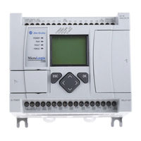
Allen-Bradley 1763-L16BBB Instruction Set Reference Manual (616 pages)
Brand:
Allen-Bradley
| Category:
Controller
| Size: 10.86 MB
Table of Contents
Firmware Revision History
3
Firmware Upgrades
3
Summary of Changes
3
Table of Contents
5
Embedded I/O
13
Micrologix 1100 Expansion I/O
15
Micrologix 1100 Expansion I/O Memory Mapping
16
I/O Addressing
24
I/O Forcing
25
Input Filtering
25
Analog Inputs
26
Latching Inputs
28
Configuring Expansion
32
I/O Using Rslogix 500
32
Common Techniques Used in this Manual
33
Preface
33
Purpose of this Manual
33
Who Should Use this Manual
33
Related Documentation
34
Rockwell Automation Support
34
Chapter 1 Controller Memory
36
Data Files
40
Types Data Files
40
Protecting Data Files During Download
42
Static File Protection
44
Password Protection
45
Clearing the Controller Memory
46
Allow Future Access Setting (OEM Lock)
47
Web View Disable (os Series B FRN 4 or Later)
47
Chapter 2 Overview
50
Chapter 2 Function Files Overview
50
Real-Time Clock Function File
51
RTA - Real Time Clock Adjust Instruction
53
Memory Module Information Function File
54
Base Hardware Information Function File
56
Communications Status File
57
Ethernet Communications Status File
71
Input/Output Status File
79
Publication 1763-RM001C-EN-P - October
80
Instruction Set
81
Using the Instruction Descriptions
82
Chapter 4 High-Speed Counter Overview
89
Programmable Limit Switch Overview
89
High-Speed Counter (HSC) Function File
90
High-Speed Counter Function File Sub-Elements Summary
92
HSC Function File Sub-Elements
93
HSL - High-Speed Counter Load
118
RAC - Reset Accumulated Value
119
Programmable Limit Switch (PLS) File
120
PTO - Pulse Train Output
127
Chapter 5
128
Pulse Train Output Function
128
Pulse Train Outputs (PTO) Function File
133
Pulse Train Output Function File Sub-Elements Summary
134
PWM - Pulse Width Modulation
149
PWM Function
150
Pulse Width Modulation (PWM) Function File
150
Pulse Width Modulated Function File Elements Summary
152
XIC - Examine if Closed XIO - Examine if Open
159
Chapter 6
161
OTE - Output Energize
161
OTL - Output Latch OTU - Output Unlatch
162
ONS - One Shot
163
OSR - One Shot Rising OSF - One Shot Falling
164
Chapter 7
167
Timer Instructions Overview
167
TON - Timer, On-Delay
171
TOF - Timer, Off-Delay
172
RTO - Retentive Timer, On-Delay
173
How Counters Work
174
CTU - Count up CTD - Count down
177
RES - Reset
178
Chapter 8
180
Using the Compare Instructions
180
EQU - Equal NEQ - Not Equal
181
GRT - Greater than LES - Less than
181
GEQ - Greater than or Equal to LEQ - Less than or Equal to
182
MEQ - Mask Compare for Equal
182
LIM - Limit Test
184
Math Instructions
187
Chapter 9 Using the Math Instructions
188
Updates to Math Status Bits
189
Using the Floating Point (F) Data File
190
ADD - Add SUB - Subtract
193
MUL - Multiply
194
DIV - Divide
194
NEG - Negate
194
CLR - Clear
194
ABS - Absolute Value
195
SCL - Scale
196
SCP - Scale with Parameters
197
SQR - Square Root
199
Chapter 10 Using Decode and Encode Instructions
201
DCD - Decode 4 to 1-Of-16
202
ENC - Encode 1-Of-16 to 4
203
FRD - Convert from Binary Coded Decimal (BCD)
204
TOD - Convert to Binary Coded Decimal (BCD)
208
GCD - Gray Code
210
Conversion Instructions
201
Chapter 11 Using Logical Instructions
211
Updates to Math Status Bits
212
AND - Bit-Wise and
213
OR - Logical or
214
XOR - Exclusive or
215
NOT - Logical NOT
216
Logical Instructions
211
Chapter 12 MOV - Move
217
MVM - Masked Move
219
Publication 1763-RM001C-EN-P - October
220
Move Instructions
217
File Instructions
222
Chapter 13 CPW - Copy Word
222
COP - Copy File
223
FLL - Fill File
225
BSL - Bit Shift Left
226
BSR - Bit Shift Right
228
FFL - First In, First out (FIFO) Load
230
FFU - First In, First out (FIFO) Unload
232
LFL - Last In, First out (LIFO) Load
234
LFU - Last In, First out (LIFO) Unload
236
SWP - Swap
238
Chapter 14 SQC- Sequencer Compare
240
Chapter 14 Sequencer Instructions SQC- Sequencer Compare
240
SQO- Sequencer Output
243
SQL - Sequencer Load
246
Chapter 15 JMP - Jump to Label
249
LBL - Label
250
JSR - Jump to Subroutine
250
SBR - Subroutine Label
250
RET - Return from Subroutine
251
SUS - Suspend
251
TND - Temporary End
251
END - Program End
252
MCR - Master Control Reset
252
Input and Output Instructions IIM - Immediate Input with Mask
255
Chapter 16
257
IOM - Immediate Output with Mask
257
REF- I/O Refresh
258
Chapter 17 Information about Using Interrupts
259
User Interrupt Instructions
263
INT - Interrupt Subroutine
263
STS - Selectable Timed Start
264
UID - User Interrupt Disable
265
UIE - User Interrupt Enable
266
UIF - User Interrupt Flush
267
Using the Selectable Timed Interrupt (STI) Function File
268
Using the Event Input Interrupt (EII) Function File
272
Publication 1763-RM001C-EN-P - October
273
Chapter 18 The PID Concept
279
The PID Equation
280
PD Data File
281
PID - Proportional Integral Derivative
282
Input Parameters
283
Output Parameters
287
Tuning Parameters
289
Runtime Errors
298
Analog I/O Scaling
299
Application Notes
300
Application Examples
304
Process Control Instruction
279
Chapter 19 General Information
309
Instruction Types and Operation
310
Protocol Overview
311
String (ST) Data File
312
Control Data File
313
ACL - ASCII Clear Buffers
314
AIC - ASCII Integer to String
316
AWA - ASCII Write with Append
317
AWT - ASCII Write
319
ABL - Test Buffer for Line
322
ACB - Number of Characters in Buffer
323
ACI - String to Integer
324
ACN - String Concatenate
326
AEX - String Extract
327
AHL - ASCII Handshake Lines
328
ARD - ASCII Read Characters
330
ARL - ASCII Read Line
331
ASC - String Search
333
ASR - ASCII String Compare
334
Timing Diagram for ARD, ARL, AWA, and AWT Instructions
336
Using In-Line Indirection
336
ASCII Instruction Error Codes
337
ASCII Character Set
339
ASCII Instructions
309
Communications Instructions Messaging Overview
341
Chapter 20
344
SVC - Service Communications
344
MSG - Message
346
The Message Element
347
Timing Diagram for the MSG Instruction
356
Communication Servicing Selection and Message Servicing Selection
359
MSG Instruction Ladder Logic
360
Local Messages
361
Configuring a Local Message
363
Local Messaging Examples
373
Remote Messages
388
Configuring a Remote Message
391
Configuring a Multi-Hop Remote Message on Ethernet/Ip Communication Channel
394
Configuring a Micrologix 1100 CIP Generic Message Via Ethernet (os Series B FRN 4 or Later)
409
MSG Instruction Error Codes
414
Special Function with MSG Instruction (os Series B FRN 4 or Later)
416
Configure MSG Setup Screen to Send SMTP Message
422
Chapter 21 RCP - Recipe
427
Data Logging
433
Queues and Records
433
Configuring Data Log Queues
437
DLG - Data Log Instruction
439
Data Log Status File
440
Retrieving (Reading) Records
442
Accessing the Retrieval File
442
Conditions that will Erase the Data Retrieval File
444
Chapter 22 LCD Overview
445
LCD Function File
446
LCD Function File Sub-Elements Summary
447
LCD Function File Sub-Elements
448
LCD - LCD Instruction
453
Programming Instructions Memory Usage and Execution Time
457
Appendix A Scan Time Worksheet
462
Appendix B Status File Overview
466
Status File Details
467
Publication 1763-RM001C-EN-P - October
468
Fault Messages and Error Codes
491
Identifying Controller Faults
491
Contacting Rockwell Automation for Assistance
499
Appendix D Communication Protocol
502
DF1 Full-Duplex Protocol
505
DF1 Half-Duplex Protocol
506
DF1 Radio Modem Protocol
517
Modbus RTU Protocol
524
ASCII Driver
534
Ethernet Driver
536
Knowledgebase Quick Starts # 17444 "Quick Start" Pulse Train Output (PTO)
539
17446 "Quick Start" Pulse Width Modulation (PWM)
542
17447 "Quick Start" High Speed Counter (HSC)
544
17465 "Quick Start" Message (MSG)
548
17501 "Quick Start" Selectable Timed Interrupt (STI)
551
17503 "Quick Start" Real Time Clock (RTC)
554
17558 "Quick Start" User Interrupt Disable (UID)
555
Appendix E 18465 "Quick Start" RTC Synchronization between Controllers
556
18498 "Quick Start" Data Logging (DLG)
559
Basic Requirements to Use 40Khz PTO and PWM in Micrologix Controller
569
Appendix F
569
PTO and PWM Function File Changes in Series B Controller
569
Rslogix500 Display Issues
570
Instruction Issues
571
Appendix 23 Binary Numbers
579
Hexadecimal Numbers
581
Hex Mask
583
Appendix H System Related
585
Serial Communications Related
585
Ethernet Communications Related
586
Application Layer Related
588
Embedded IO Configuration Related
588
Web-Server Related
588
Rslogix500 Compatibility
588
Publication 1763-RM001C-EN-P - October
589
Advertisement
Advertisement
Related Products
Allen-Bradley 1763-L16AWA
Allen-Bradley 1763-L16BWA
Allen-Bradley 1763-L16DWD
Allen-Bradley 1769-L31 CompactLogix 5331
Allen-Bradley 1769-L30ERM
Allen-Bradley 1769-L30ER-NSE
Allen-Bradley 1769-L33ERM
Allen-Bradley 1769-L24ERQBFC1B
Allen-Bradley 1769-L18ER-BB1B
Allen-Bradley 1768-L45S CompactLogix 5345S
Allen-Bradley Categories
Control Unit
Controller
I/O Systems
Switch
Power Supply
More Allen-Bradley Manuals
Login
Sign In
OR
Sign in with Facebook
Sign in with Google
Upload manual
Upload from disk
Upload from URL