Sign In
Upload
Manuals
Brands
Allen-Bradley Manuals
Control Unit
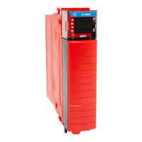
1756-IB16S
Allen-Bradley 1756-IB16S Manuals
Manuals and User Guides for Allen-Bradley 1756-IB16S. We have
1
Allen-Bradley 1756-IB16S manual available for free PDF download: User Manual
Allen-Bradley 1756-IB16S User Manual (136 pages)
ControlLogix Digital Safety I/O Modules
Brand:
Allen-Bradley
| Category:
Control Unit
| Size: 3.97 MB
Table of Contents
Table of Contents
3
Preface
7
Summary of Changes
7
Terminology
7
Additional Resources
8
Digital Safety I/O Module Operation in a Control System
9
Overview
10
Controller and Software Compatibility
11
Determine Conformity
12
Overall System Safety Function
12
1756-IB16S Single-Channel Point Operation Type
14
Point Operation Type
14
Obtain Firmware
15
Safety Precautions
16
Safety Application Requirements
17
Safe State
18
Configuration Signature and Ownership
19
Out-Of-Box State
20
Reset 1756 Controllogix Digital Safety I/O Modules to
20
About the Modules
21
Local I/O Modules
23
Local I/O Modules or Remote I/O Modules
23
Ownership
24
Remote I/O Modules
24
Construct a System
25
Local I/O Modules
25
Configure the Modules
26
Remote I/O Modules
26
Modules
27
Requested Packet Interval
30
Connection over an Ethernet/Ip Network
31
Input Module Operation
31
Local 1756 Controllogix Digital Safety Input Modules
31
Output Module Operation
32
Remote 1756 Controllogix Digital Safety Input Modules
32
Local Safety Output Modules
33
Remote Safety Output Modules
33
External Means
35
Protected Operations
36
Input Module Compatibility
38
Output Module Compatibility
38
Software Configurable
39
Module Data Quality Reporting
40
Fault and Status Reporting
41
Module Inhibiting
41
Electronic Keying
43
More Information
43
Module Firmware
44
Producer/Consumer Communication
44
Chapter 3, 1756-IB16S Input Module Features
45
Overview
45
Safety Application Suitability Level
46
Use Test Output with a Safety Input
47
Single-Channel Point Operation Type
49
Latch Fault until Reset Via Output Tag' Mode Is Disabled
50
Latch Fault until Reset Via Output Tag' Mode Is Enabled
50
Safety Input Delay Time
50
Safety Input Fault Reset
50
Off to on Delay
51
Data Transfer at RPI
52
Module Health Diagnostic
52
On to off Delay
52
Point Diagnostics
53
Fault and Status Reporting
54
Field Power Loss Detection
55
Ground Condition
56
Short Circuit Protection
56
Test Output Recovery after Overload or Short Circuit to
56
Chapter 4, 1756-OBV8S Output Module Features
57
Overview
58
Safety Application Suitability Level
59
Safety Output with Test Pulse
60
Single-Channel Point Operation Type
61
Dual-Channel Point Operation Type
62
Latch Fault until Reset Via Output Tag' Mode Is Disabled
63
Latch Fault until Reset Via Output Tag' Mode Is Enabled
63
Safety Output Fault Reset
63
Fault and Status Reporting
64
Module Health Diagnostics
64
Point Diagnostics
65
Field Power Loss Detection
66
No Load Detection
67
Short Circuit Protection
68
Other Conditions that Can Trigger the Short Circuit Diagnostic on the 1756-OBV8S Module
69
Ground Condition
70
Thermal Shutoff
70
Configurable Channel-Level Output State in Program Mode or Fault Mode
71
Fault and Status Reporting
71
Fault Mode
71
Connection Fault Handling
72
Output Behavior Immediately after a Connection Fault
72
Output State Once Connection Is Re-Established
72
Enable Forces
73
Forcing
73
Check Force Status
74
Disable or Remove a Force
74
GSV Instruction
75
Configure and Replace Safety Modules
77
Create a New Module
78
New Local Safety Module
78
New Remote I/O Module
80
Edit the Module Configuration Common Categories
82
General Category
83
Connection Category
85
Safety Category
86
Module Info Category
87
Edit the 1756-IB16S Module Configuration Categories
88
Input Points Category
88
Test Output Points Category
89
Edit the 1756-OBV8S Module Points Category
90
Fault Mode
91
Point Mode
91
View the Module Tags
92
Replace a Safety Module
93
Reset to Out-Of-Box Configuration
93
Replace a Module in a Logix 5000 System
95
Module Status Indicators
103
OK Status Indicators
104
Use the Logix Designer Application for Troubleshooting
105
Warning Signal in the I/O Configuration Tree
105
Categories
106
Status and Fault Information in Module Properties
106
Module and Point Diagnostics
108
Logix Designer Application Tag Editor
110
Internalfault Triggered on the Safety Output Module
111
Access the Tags
114
Name Conventions
114
1756-IB16S Module Tags
115
Input Tags
115
Output Tags
116
1756-OBV8S Module Tags
117
Input Tags
117
Output Tags
118
Before You Begin
119
1756-IB16S Module Wiring Diagrams
120
1756-OBV8S Module Wiring Diagrams
123
Bipolar Mode
123
Sourcing Mode
126
1756-IB16S Safety Data
130
1756-OBV8S Safety Data
131
Index
133
Advertisement
Advertisement
Related Products
Allen-Bradley ControlLogix 1756-IA16I
Allen-Bradley 1756-IA32
Allen-Bradley ControlLogix 1756-IH16I
Allen-Bradley ControlLogix 1756-IM16I
Allen-Bradley ProcessLogix 1756-IF6I
Allen-Bradley ControlLogix 1756-IT6I
Allen-Bradley 1756-IT6I2
Allen-Bradley ProcessLogix 1756-IF16
Allen-Bradley ControlLogix 1756-IF6CIS
Allen-Bradley ControlLogix 1756-IR6I
Allen-Bradley Categories
Control Unit
Controller
I/O Systems
Switch
Power Supply
More Allen-Bradley Manuals
Login
Sign In
OR
Sign in with Facebook
Sign in with Google
Upload manual
Upload from disk
Upload from URL