Sign In
Upload
Manuals
Brands
Allen-Bradley Manuals
I/O Systems
1734-IB8
User Manuals: Allen-Bradley 1734-IB8 I/O Digital
Manuals and User Guides for Allen-Bradley 1734-IB8 I/O Digital. We have
3
Allen-Bradley 1734-IB8 I/O Digital manuals available for free PDF download: User Manual, Installation Instructions Manual
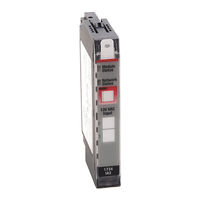
Allen-Bradley 1734-IB8 User Manual (221 pages)
POINT series I/O Digital and Analog Modules; POINTBlock series I/O Modules
Brand:
Allen-Bradley
| Category:
I/O Systems
| Size: 9.95 MB
Table of Contents
Who Should Use this Manual
5
Additional Resources
6
Table of Contents
9
About the Modules
17
Chapter 1
17
About this Chapter
17
Digital Modules
17
Input Modules
18
Output Modules
18
Relay Output Modules
19
Analog Modules
19
Input Modules
20
Output Modules
20
Specialty Modules
21
Power Supplies, Wiring Base Assemblies, and Miscellaneous Modules
21
Chapter 2
23
About this Chapter
23
Install the Mounting Base Assembly
25
Install an I/O Module
27
Install the Removable Terminal Block
28
Remove a Mounting Base
29
Wiring Digital Modules
30
1734-IB2, 1734-IB4, and 1734-IB8 Sink Input Modules
30
1734-IB4D Modules
34
1734-IV2, 1734-IV4, and 1734-IV8 Source Input Modules
35
1734-OB2E, 1734-OB4E, 1734-OB8E, 1734-OB2, 1734-OB4, and 1734-OB8 Protected Output Modules
37
1734-OB2EP Protected Output Modules
37
1734-OW2 and 1734-OW4 Relay Output Modules
42
1734-OW2 Modules with Load Powered by Internal Power Bus
42
Wiring Diagram
42
1734-OW2 Modules with Load Powered by
42
1734-OW4 Modules with Load Powered by
43
1734-OX2 2-Relay Output Modules
48
1734-OX2 Module with Load Powered by Internal Power Bus Wiring Diagram
48
1734-OX2 Modules with Load Powered by External Power Bus
49
Wiring Diagram
49
1734-IA2 and 1734-IA4 120 V AC Input Modules
52
1734-IM2 and 1734-IM4 220V AC Input Modules
54
1734-IM2 120V AC 2 Input Module Wiring Diagram
55
1734-OA2 and 1734- OA4 120/220V AC Output Modules
56
1734-OA2 AC 2 Output Module Wiring Diagram
56
1734-OA4 AC 2 Output Module Wiring Diagram
57
Wiring Analog Modules
58
1734-IE2C Analog Current Input Module
58
1734-IE2C Analog Current Input Module Wiring Diagram
58
1734-IE2V Analog Voltage Input Module
59
1734-IE2V Analog Voltage Input Module Wiring Diagram
59
1734-OE2C Analog Current Output Module
60
1734-OE2V Analog Voltage Output Module
61
Wiring Power Distribution and Other Modules
62
1734-PDN Communication Interface Module
62
1734-PDN Module Wiring Diagram
62
1734-FPD Field Potential Distributor Module
63
1734-FPD Modules for 12/24V DC Wiring Diagram
64
1734-EP24DC Expansion Power Supply
66
12/24V DC Wiring Diagram
67
1734-EPAC AC Expansion Power Supply
69
120/240V AC Wiring Diagram
69
1734-ARM Address Reserve Module
71
1734-CTM and 1734-VTM Modules
72
Sink Input Wiring Diagram
72
Source Input Wiring Diagram
73
Source Output Wiring Diagram
73
Sink Output Wiring Diagram
73
General Purpose Wiring Diagram
74
Install POINT I/O Modules
23
Chapter 3
75
About this Chapter
75
Wiring Pointblock Modules
75
1734D-IB8XOB8 Pointblock 8 DC In/8 DC out Modules
75
Input/8 Output Module Wiring Diagram
76
Sink Input Wiring Diagram
76
Output Wiring Diagram
77
Input/8 Relay Output Module Wiring Diagram
79
Sink Input Wiring
80
1734D-IA8XOA8 Pointblock 8 AC In/8 AC out Modules
82
Input Wiring Diagram
83
Output Wiring Diagram
84
Input Wiring Diagram
86
Output Wiring Diagram
87
1734D-IA16 Pointblock 16 AC Input Modules
88
Wire the 16 AC Input Module Wiring Diagram
88
Input Wiring Diagram
89
1734D-IB16 Pointblock 16 DC Input Modules
90
16 DC Input Module Wiring Diagram
91
Sink Input Wiring Diagram
91
Install Pointblock I/O Modules
75
Chapter 4
93
About this Chapter
93
Digital Input Modules
93
Digital DC Input Modules
93
Digital AC Input Modules
95
Digital Output Modules
96
Digital DC Output Modules
96
Digital AC Output Modules
98
Relay Output Modules
99
Analog Input Modules
100
Data
101
Communicate with Your Module
101
Scaling
102
Channel Status
102
Latch Alarms
103
Alarm Disable
104
Calibration Status
104
Digital Filter
104
Update Rate
104
Notch Filter
104
Alarms
105
Range Status
105
Channel Indicator Behavior
106
Analog Output Modules
106
Data
106
Operational Modes
108
Scaling
108
Fault and Idle/Program Mode Action
109
Channel Status
109
Low and High Clamps
110
Latch Alarms
111
Alarm Disable
111
Channel Indicators
111
Pointblock I/O Modules
112
POINT I/O Module Data
93
Calibrate Your Analog Modules
117
Chapter 5
117
About this Chapter
117
Tools Required to Calibrate Your Analog Modules
118
Calibrate the Analog Current Input Module
119
Calibrate the Analog Current Output Module
123
Calibrate the Analog Voltage Input Module
128
Calibrate the Analog Voltage Output Module
131
Chapter 6 About this Chapter
137
About Module Diagnostics
137
Network and Module Status Indications
138
Troubleshoot Digital Modules
139
1734-IB2, 1734-IB4, and 1734-IB8 Sink Input Modules
139
1734-IB4D Sink Input Modules with Diagnostics
139
1734-OB2EP Protected Output Module
141
1734-IV2, 1734-IV4, and 1734-IV8 Source Input Modules
141
1734-OW2 and 1734-OW4 Relay Output Modules
142
1734-OX2 Relay Output Module
143
1734-IA2 and 1734-IA4 120V AC Input Module
143
1734-OA2 and 1734-OA4 120/220V AC Output Module
144
1734-IM2 and 1734-IM4 220V AC Input Module
144
Troubleshoot Analog Modules
145
1734-IE2C Analog Current Input Module
145
1734-OE2C Analog Current Output Module
145
1734-IE2V Analog Voltage Input Module
146
1734-OE2V Analog Voltage Output Module
146
Troubleshoot I/O Communication Modules
147
1734-ADN (X) Devicenet Adapter
148
1734-ACNR Controlnet Adapter
150
1734-APB PROFIBUS Adapter
152
1734-AENT Ethernet/Ip Adapter
154
Troubleshoot with the Indicators
137
Appendix A
157
About this Appendix
157
Digital Module Default Data Maps
158
1734-IB2 Sink Input Module
158
1734-IB4 Sink Input Module
158
1734-IB8 Sink Input Module
158
1734-IB4D Sink Input Modules with Diagnostics
158
1734-IV2 Source Input Module
160
1734-IV4 Source Input Module
160
1734-IV8 Source Input Module
160
1734-IA2 Input Module
161
1734-IA4 Input Module
161
1734-IM2 Input Module
161
1734-IM4 Input Module
161
1734-OA2 Output Module
162
1734-OA4 Output Module
162
1734-OB2EP Protected Output Module
163
1734-OV2E Output Module
164
1734-OV4E Output Module
164
1734-OV8E Output Module
164
1734-OW2 Relay Sink/Source Output Module
165
1734-OW4 Relay Sink/Source Output Module
165
1734-OX2 Relay Output Module
165
Analog Module Default Data Maps
166
1734-IE2C Analog Current Input Module
166
1734-IE2V Analog Voltage Input Module
166
1734-OE2C Analog Current Output Module
167
1734-OE2V Analog Voltage Output Module
167
Default Data Maps
157
Appendix B
169
About this Appendix
169
POINT I/O Module with a 1734-PDN Module
169
Pointblock Module
171
About this Appendix
173
Mounting Dimensions
169
Appendix C
173
Use the Help Button
173
Configure Digital Modules
173
About Fault/Program Action and Configuration Dialogs
175
Configure Analog Modules
183
About this Appendix
197
Appendix D
197
Configuring POINT I/O Modules
197
Commissioning a Node
197
Using the Rsnetworx Commissioning Tool
197
Use Sequential Auto Addressing
198
Using Third-Party Configuration Software
199
Configure Digital Modules Using Rsnetworx Software
199
Configure Analog Modules Using Rsnetworx Software
211
Advertisement
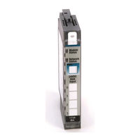
Allen-Bradley 1734-IB8 Installation Instructions Manual (24 pages)
point i/o input modules series C
Brand:
Allen-Bradley
| Category:
I/O Systems
| Size: 0.8 MB
Table of Contents
Table of Contents
1
Important User Information
2
Environment and Enclosure
3
Preventing Electrostatic Discharge
3
North American Hazardous Location Approval
4
European Hazardous Location Approval
5
Before You Begin
6
About the Module
7
Install the Mounting Base
7
Install the Module
8
Install the Removable Terminal Block
9
Remove a Mounting Base
10
Communicate with Your Module
11
Wire the Module
12
Interpret Status Indicators
18
Specifications
20
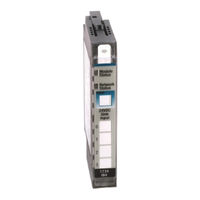
Allen-Bradley 1734-IB8 Installation Instructions Manual (16 pages)
POINT I/O Input Modules
Brand:
Allen-Bradley
| Category:
I/O Systems
| Size: 1.21 MB
Table of Contents
Table of Contents
1
Summary of Changes
1
Before You Begin
4
Install the Mounting Base
5
Install the Module
6
Install the Removable Terminal Block
7
Remove a Mounting Base
8
Wire the Module
8
Communicate with the Module
12
Interpret Status Indicators
12
Specifications
13
Advertisement
Advertisement
Related Products
Allen-Bradley 1734-IB2
Allen-Bradley 1734-IB4
Allen-Bradley POINT I/O 1734-IB4D
Allen-Bradley 1734-IB4K
Allen-Bradley 1734-IB8K
Allen-Bradley 1734-IE2V
Allen-Bradley 1734- IV2
Allen-Bradley POINT I/O 1734-IR2E
Allen-Bradley 1734-IT2IK
Allen-Bradley 1734-IR2K
Allen-Bradley Categories
Control Unit
Controller
I/O Systems
Switch
Power Supply
More Allen-Bradley Manuals
Login
Sign In
OR
Sign in with Facebook
Sign in with Google
Upload manual
Upload from disk
Upload from URL