Sign In
Upload
Manuals
Brands
Agilent Technologies Manuals
Water Pump
G7081B
Agilent Technologies G7081B Manuals
Manuals and User Guides for Agilent Technologies G7081B. We have
2
Agilent Technologies G7081B manuals available for free PDF download: Operating Manual
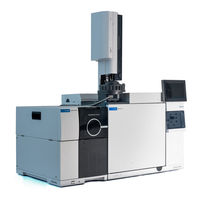
Agilent Technologies G7081B Operating Manual (254 pages)
Brand:
Agilent Technologies
| Category:
Water Pump
| Size: 16.42 MB
Table of Contents
About this Manual
3
Hardware User Information
4
Table of Contents
5
1 Introduction
13
5977B Series MSD Version
14
Abbreviations Used
15
The 5977B Series MSD
17
Physical Description
17
Vacuum Gauge
18
MSD Hardware Description
19
Important Safety Warnings
21
Many Internal Parts of the MSD Carry Dangerous Voltages
21
Electrostatic Discharge Is a Threat to MSD Electronics
22
Many Parts Are Dangerously Hot
22
The Oil Pan under the Foreline Pump Can be a Fire Hazard
23
Hydrogen Safety
24
GC Precautions
24
Dangers Unique to GC/MSD Operation
25
Hydrogen Accumulation in an MSD
25
Precautions
26
Safety and Regulatory Certifications
28
Information
29
Symbols
29
Electromagnetic Compatibility
30
Sound Emission Declaration
30
Intended Use
31
Cleaning/Recycling the Product
31
Accidental Liquid Spillage
31
Moving or Storing the MSD
31
To Replace the Primary Fuses
32
2 Installing 8890 GC Columns
35
Columns
36
Conditioning Columns
36
Conditioning Ferrules
37
Tips and Hints
37
To Install a Capillary Column in a Split/Splitless Inlet
38
To Condition a Capillary Column
41
To Install a Capillary Column in the GC/MSD Interface Using the Self-Tightening Column Nut
42
To Install a Capillary Column in the GC/MSD Interface Using a Standard Column Nut
47
Nut
47
To Install the GC/MSD Interface Tip Seal
50
The GC/MSD Interface for an 8890 Series GC
52
3 Installing Intuvo 9000 GC Columns
55
Columns
56
Conditioning Columns
57
Tips and Hints
57
To Replace an Intuvo GC Column
59
To Replace an Intuvo 9000 GC Gasket
63
To Install a Column Guard or Jumper Chip
64
To Replace the 9000 GC/MS Tail
68
To Condition an Intuvo Capillary Column
72
To Install the GC/MSD Interface Tip Seal
74
The GC/MSD Interface for a 9000 Series GC
76
4 Installing 7890 GC Columns
77
Columns
78
Conditioning Columns
79
Conditioning Ferrules
79
Tips and Hints
79
To Install a Capillary Column in a Split/Splitless Inlet
80
To Condition a Capillary Column
83
To Install a Capillary Column in the GC/MSD Interface Using the Self-Tightening Column Nut
84
To Install a Capillary Column in the GC/MSD Interface Using a Standard Column Nut
89
Nut
89
To Install the GC/MSD Interface Tip Seal
93
To Calibrate Column Flow Linear Velocity in a 7890 GC
95
The GC/MSD Interface for a 7890B Series GC
98
5 Operating in EI Mode
101
Operating the MSD from the DS
103
Operating the MSD from the 7890 GC Control Panel
104
Configuring the MSD through the Web User Interface (WUI)
108
To Change the Network Settings of the MSD
108
Emodule Mini Display Readout
111
Front Panel Instrument Status LED
112
Before You Turn on the MSD
113
Pumping down
114
Controlling Temperatures
114
Controlling Column Flow
115
Controlling Jetclean Hydrogen Flow
115
Venting the MSD
116
To View MSD Temperature and Vacuum in Manual Tune
117
To Set Monitors for MSD Temperature and Vacuum Status
119
To Set Analyzer Temperatures from the Instrument Control View
122
To Set the GC/MSD Interface Temperature from Masshunter
124
To Monitor High Vacuum Pressure
125
To Tune the MSD in EI Mode
127
To Set the Operation Mode for the Optional Jetclean System
129
To Set the Jetclean Parameters for the Clean Only Mode
130
To Verify EI System Performance
131
To Perform High-Mass Testing
132
To Open the MSD Covers
135
To Vent the MSD
136
To Pumpdown the MSD
139
6 Operating in CI Mode
144
General Guidelines
144
CI Autotune
145
To Operate the CI MSD
147
To Pumpdown the MSD in CI Mode
148
To Set up the Software for CI Operation
149
To Operate the Reagent Gas Flow Control Module
151
To Set up Methane Reagent Gas Flow
154
To Use Other Reagent Gases
156
To Perform a PCI Autotune (Methane Only)
159
To Perform an NCI Autotune (Methane Reagent Gas)
161
To Verify PCI Performance
163
To Verify NCI Performance
164
To Monitor CI Mode High Vacuum Pressure
165
7 General Maintenance
167
Before Starting
168
Maintaining the Vacuum System
173
Maintaining the Analyzer
174
To Open the Analyzer Chamber
176
To Remove the EI HES
178
To Connect/Disconnect Wiring to the EI HES
180
To Disassemble the EI HES
181
To Clean the EI HES
184
To Assemble the EI HES
187
To Remove the EI HES Filaments
192
To Install the EI HES Filament
194
To Install the EI HES
195
To Remove the EI XTR, SS, or Inert Source
196
To Connect/Disconnect Wiring from the EI XTR, SS, and Inert Sources
197
To Disassemble the EI SS or EI Inert Source
198
To Disassemble the EI XTR Source
201
To Clean an EI XTR, SS, or Inert Source
204
To Assemble an EI SS or Inert Source
209
To Assemble the EI XTR Source
212
To Replace a Filament in an EI XTR, SS, or Inert Source
215
To Install the EI XTR, SS, or Inert Source
217
To Replace the Electron Multiplier Horn
218
To Close the Analyzer Chamber
220
101 CI Maintenance
221
General Information
222
To Set up Your MSD for CI Operation
222
To Switch from the EI HES to the CI Source
223
To Remove the EI HES Radiator
224
To Connect/Disconnect Wiring to the EI HES Radiator
225
To Install the CI Source Radiator
227
To Switch from the CI Source to the EI HES
229
To Remove the CI Source Radiator
230
To Install the EI HES Radiator
232
To Switch from an EI XTR, SS, or Inert Source to the CI Source
233
To Switch from the CI Source to an EI XTR, SS, or Inert Source
234
To Remove the CI Source
235
To Connect/Disconnect Non-HES Model Wiring from the CI Source
236
To Connect/Disconnect EI HES Model Wiring to the CI Source
237
To Disassemble the CI Source
238
To Clean the CI Source
241
To Assemble the CI Source
244
To Remove the CI Source Filament
247
To Install a CI Source Filament
249
To Install the CI Source
250
Advertisement
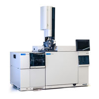
Agilent Technologies G7081B Operating Manual (234 pages)
Brand:
Agilent Technologies
| Category:
Security Sensors
| Size: 15.46 MB
Table of Contents
About this Manual
3
Where to Find more Information
4
Table of Contents
5
Introduction
11
5977C Series MSD Version
12
Abbreviations Used
13
The 5977C Series MSD
15
Physical Description
15
Vacuum Gauge
16
MSD Hardware Description
17
Important Safety Warnings
19
Many Internal Parts of the MSD Carry Dangerous Voltages
19
Electrostatic Discharge Is a Threat to MSD Electronics
20
Many Parts Are Dangerously Hot
20
The Oil Pan under the Foreline Pump Can be a Fire Hazard
21
Hydrogen Safety
22
GC Precautions
22
Dangers Unique to GC/MSD Operation
23
Hydrogen Accumulation in an MSD
23
Precautions
24
Safety and Regulatory Certifications
28
Information
29
Symbols
29
Electromagnetic Compatibility
30
Sound Emission Declaration
30
Intended Use
31
Cleaning/Recycling the Product
31
Accidental Liquid Spillage
31
Moving or Storing the MSD
31
To Replace the Primary Fuses
32
Installing 8890 GC Columns
35
Columns
36
Conditioning Columns
36
Conditioning Ferrules
37
Tips and Hints
37
To Install a Capillary Column in a Split/Splitless Inlet
38
To Condition a Capillary Column
41
To Install a Capillary Column in the GC/MSD Interface Using the Self-Tightening Column Nut
42
To Install a Capillary Column in the GC/MSD Interface Using a Standard Column Nut
47
Nut
47
To Install the GC/MSD Interface Tip Seal
50
The GC/MSD Interface for an 8890 Series GC
52
Installing Intuvo 9000 GC Columns
55
Columns
56
Conditioning Columns
57
Tips and Hints
57
To Replace an Intuvo GC Column
59
To Replace an Intuvo 9000 GC Gasket
63
To Install a Column Guard or Jumper Chip
64
To Replace the 9000 GC/MS Tail
68
To Condition an Intuvo Capillary Column
72
To Install the GC/MSD Interface Tip Seal
74
The GC/MSD Interface for a 9000 Series GC
76
Operating in EI Mode
77
Operating the MSD from the DS
79
Configuring the MSD through the Web User Interface (WUI)
80
To Change the Network Settings of the MSD
80
Emodule Mini Display Readout
83
Front Panel Instrument Status LED
84
Before You Turn on the MSD
85
Pumping down
86
Controlling Temperatures
86
Controlling Column Flow
87
Controlling Jetclean Hydrogen Flow
87
Venting the MSD
88
To View MSD Temperature and Vacuum in Manual Tune
89
To Set Monitors for MSD Temperature and Vacuum Status
91
To Set Analyzer Temperatures from the Instrument Control View
94
To Set the GC/MSD Interface Temperature from Masshunter
96
To Monitor High Vacuum Pressure
98
To Tune the MSD in EI Mode
100
To Set the Operation Mode for the Optional Jetclean System
102
To Set the Jetclean Parameters for the Clean Only Mode
103
To Verify EI System Performance
104
To Perform High-Mass Testing
105
To Open the MSD Covers
108
To Vent the MSD
109
To Pumpdown the MSD
112
Operating in CI Mode
115
General Guidelines
116
CI Autotune
117
To Operate the CI MSD
119
To Pumpdown the MSD in CI Mode
120
To Set up the Software for CI Operation
121
To Operate the Reagent Gas Flow Control Module
123
To Set up Methane Reagent Gas Flow
126
To Use Other Reagent Gases
128
To Perform a PCI Autotune (Methane Only)
131
To Perform an NCI Autotune (Methane Reagent Gas)
133
To Verify PCI Performance
135
To Verify NCI Performance
136
To Monitor CI Mode High Vacuum Pressure
137
General Maintenance
139
Before Starting
141
Maintaining the Vacuum System
146
Maintaining the Analyzer
147
To Open the Analyzer Chamber
149
To Remove the EI HES
151
To Connect/Disconnect Wiring to the EI HES
153
To Disassemble the EI HES
154
To Clean the EI HES
157
To Assemble the EI HES
160
To Remove the EI HES Filaments
165
To Install the EI HES Filament
167
To Install the EI HES
168
To Remove the EI XTR, SS, Inert, or HydroNert Source
169
To Connect/Disconnect Wiring from the EI XTR, SS, and Inert Sources
170
To Connect/Disconnect Wiring from the EI Hydro Nert Source
171
To Connect/Disconnect Wiring from the EI HydroNert Source
171
To Disassemble the EI SS or EI Inert Source
172
To Disassemble the EI XTR Source
175
To Disassemble the EI HydroNert Source
178
To Clean an EI XTR, SS, or Inert Source
181
To Clean the EI HydroNert Source
185
To Assemble an EI SS or Inert Source
188
To Assemble the EI XTR Source
191
To Assemble the EI HydroNert Source
194
To Replace a Filament in an EI XTR, SS, Inert, or HydroNert Source
197
Source
199
To Install the EI XTR, SS, Inert, or HydroNert Source
199
To Replace the Electron Multiplier Horn
200
To Close the Analyzer Chamber
202
General Information
204
To Set up Your MSD for CI Operation
204
CI Maintenance
204
To Switch from the EI HES to the CI Source
205
To Remove the EI HES Radiator
206
To Connect/Disconnect Wiring to the EI HES Radiator
207
To Install the CI Source Radiator
209
To Switch from the CI Source to the EI HES
211
To Remove the CI Source Radiator
212
To Install the EI HES Radiator
214
To Switch from an EI XTR, SS, or Inert Source to the CI Source
215
To Switch from the CI Source to an EI XTR, SS, or Inert Source
216
To Remove the CI Source
217
To Connect/Disconnect Non-HES Model Wiring from the CI Source
218
To Connect/Disconnect EI HES Model Wiring to the CI Source
219
To Disassemble the CI Source
220
To Clean the CI Source
223
To Assemble the CI Source
226
To Remove the CI Source Filament
229
To Install a CI Source Filament
231
To Install the CI Source
232
Advertisement
Related Products
Agilent Technologies G7080B
Agilent Technologies G7077B
Agilent Technologies G7078B
Agilent Technologies G7079B
Agilent Technologies G7110B
Agilent Technologies G7111A
Agilent Technologies G7111B
Agilent Technologies G7161A
Agilent Technologies G7161B
Agilent Technologies G7104A
Agilent Technologies Categories
Measuring Instruments
Laboratory Equipment
Test Equipment
Water Pump
Power Supply
More Agilent Technologies Manuals
Login
Sign In
OR
Sign in with Facebook
Sign in with Google
Upload manual
Upload from disk
Upload from URL