Sign In
Upload
Manuals
Brands
Agilent Technologies Manuals
Inverter
E8257C
Agilent Technologies E8257C Manuals
Manuals and User Guides for Agilent Technologies E8257C. We have
5
Agilent Technologies E8257C manuals available for free PDF download: Service Manual, User Manual, Programming Manual, Manual, Installation Manual
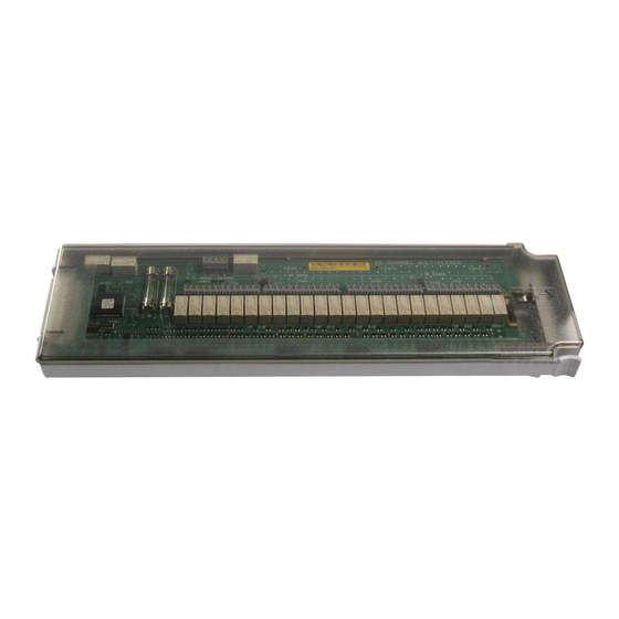
Agilent Technologies E8257C Service Manual (291 pages)
PSG Signal Generators
Brand:
Agilent Technologies
| Category:
Portable Generator
| Size: 12.28 MB
Table of Contents
Table of Contents
3
Troubleshooting
11
Electrostatic Discharge (ESD) Information
12
Handling of Electronic Components and ESD
12
Getting Started with Troubleshooting
13
Running Self-Test
13
A18 CPU Turn-On Test
14
Failure Symptoms
14
A2 Display Not Functioning or A2 Display Not Functioning after Turn-On
14
A18 CPU Fails to Complete the Turn-On Check
14
Checking the A18 CPU Voltages
15
Verifying the A18 CPU Turn-On Sequence
15
No Instrument Control from the Front Panel
16
Error Messages
16
Self-Test Failures and Related Troubleshooting
17
Troubleshooting Assembly-Level Problems
20
Front Panel Display Assembly Troubleshooting
21
Power Supply Troubleshooting
27
Self-Tests 1Xx for the A13 I/Q Multiplexer
40
Self-Tests 2Xx: A5 Sampler Self-Test Errors
42
Self-Tests 3Xx: A7 Reference (Standard) Self-Test Errors
44
Self-Tests 4Xx: A8 Output Self-Test Errors
45
Self-Tests 6Xx: A9 YIG Driver Self-Test Errors
48
Self-Tests 7Xx: A6 Frac-N Self-Test Errors
51
Self-Tests 9Xx: A10 ALC Self-Test Errors
55
Self-Tests 10Xx: A7 Reference (Option UNR) Self-Test Errors
57
Self-Tests 11Xx: A18 CPU Self-Test Errors
59
Self-Tests 12Xx: A26 MID Self-Test Errors
61
Self-Tests 13Xx: A11 Analog/Pulse Modulation Generator Self-Test Errors
66
Self-Tests 16Xx for the A14 Baseband Generator (Option 002/602)
69
Self-Tests 22Xx: A8 Output Self-Test Errors
72
Troubleshooting Unlocks
74
A6 Frac-N Loop Unlock
74
513 1 Ghz out of Lock
74
514 Reference Oven Cold
74
515 10 Mhz Signal Bad
75
520 Sampler Unlocked
75
521 YO Loop Unlocked
75
625 Internal Pulse Generator Unlock
76
626 Internal Mod Source Unlock
76
Troubleshooting Unlevels
77
Troubleshoot and Correct any Unlock Problems before Troubleshooting Unleveled Problems
77
Troubleshooting Adjustment Problems
81
Troubleshooting ADC Adjustment Failures
83
Troubleshooting Performance Test Problems
84
Troubleshooting the RF Path
86
ALC and RF Problems
86
Troubleshooting Pulse Modulation
87
Troubleshooting AT1 Attenuator
89
Troubleshooting Harmonic Spurious
90
20 Ghz Models
90
40 Ghz Models Only
91
Troubleshooting Non-Harmonic Spurious
93
Troubleshooting Option UNR Phase Noise
94
Overall Description
95
A19 Power Supply
95
A18 Cpu
96
Input/Output Interface
96
Frequency Generation
97
Reference/Synthesis Loop Description
103
A7 Reference
104
A5 Sampler (CW Mode Only)
105
A6 Frac-N
105
A9 YIG Driver
106
A28 YIG Oscillator (YO)
107
A29 20 Ghz Doubler
107
Reference/Synthesis Loop
107
RF Path Description (Frequency Generation, Level Control, and Modulation)
110
A29 20 Ghz Doubler
110
A6 Frac-N
111
A8 Output
111
A30 Modulation Filter
112
A27 40 Ghz Doubler (Analog Models Only)
112
A23 Lowband Coupler/Detector, A24 Highband Coupler, and A25 High Band Detector
112
Ghz Fast Pulse Modulator (Option 1E6)
113
A35 3-20 Ghz I/Q Modulator (Vector Models Only)
113
ALC Loop
113
Modulation (AM, FM, ΦM, and Pulse)
114
Digital Modulation
115
Approximate Device Gains and Losses
117
Self-Test Overview
120
How Self-Test Works
120
Independent Failures
120
Contacting Agilent Technologies
121
Agilent Sales and Service Offices
123
Packaging a Signal Generator for Return
124
Assembly Replacement
126
Before You Replace an Assembly
127
After Replacing or Repairing an Assembly
127
Assemblies that You Can Replace
128
Outer Instrument Cover
130
Tools Required
130
Removal Procedure
130
Replacement Procedure
130
Inner Instrument Cover
132
Tools Required
132
Removal Procedure
132
Replacement Procedure
132
Front Panel
134
Tools Required
134
Removal Procedure
134
Replacement Procedure
135
A1 Keyboard
137
Tools Required
137
Removal Procedure
137
Replacement Procedure
137
A2 Display
139
Tools Required
139
Removal Procedure
139
Replacement Procedure
139
A2DS1 Display Backlight
141
Tools Required
141
Removal Procedure
141
Replacement Procedure
141
A3 Power Switch
143
Tools Required
143
Removal Procedure
143
Replacement Procedure
143
A4 Inverter
145
Tools Required
145
Removal Procedure
145
Replacement Procedure
145
A5 Sampler, A6 Frac-N, A7 Reference (Standard and Option UNR), and A8 Output
147
Tools Required
147
Removal Procedure
147
Replacement Procedure
147
A9 YIG Driver
149
Tools Required
149
Removal Procedure
149
Replacement Procedure
149
A10 Alc
151
Tools Required
151
Removal Procedure
151
Replacement Procedure
151
A11 Pulse/Analog Modulation Generator
153
Tools Required
153
Removal Procedure
153
Replacement Procedure
153
A12 Pulse Modulator Board (Option 1E6)
155
Tools Required
155
Removal Procedure
155
Replacement Procedure
155
A13 I/Q MUX (E8267C Models Only)
157
Tools Required
157
Removal Procedure
157
Replacement Procedure
157
A14 Baseband Generator (E8267C Models Only)
159
Tools Required
159
Removal Procedure
159
Replacement Procedure
159
A17 Baseband Generator Interface (E8267C Models Only)
161
Tools Required
161
Removal Procedure
161
Replacement Procedure
161
A18 Cpu
163
Tools Required
163
Removal Procedure
163
Replacement Procedure
163
A18Bt1
165
Tools Required
165
Removal Procedure
165
Replacement Procedure
165
A19 Power Supply
167
Tools Required
167
Removal Procedure
167
Replacement Procedure
167
Rear Panel (Standard)
169
Tools Required
169
Removal Procedure
169
Replacement Procedure
170
Rear Panel (Option 1EM)
172
Tools Required
172
Removal Procedure
172
Replacement Procedure
173
A20 SMI (Source Module Interface)
175
Tools Required
175
Removal Procedure
175
Replacement Procedure
175
A21 Rear-Panel Interface
177
Tools Required
177
Removal Procedure
177
Replacement Procedure
177
A22 Line Module
179
Tools Required
179
Removal Procedure
179
Replacement Procedure
179
AT1 115 Db Attenuator
181
Tools Required
181
Removal Procedure
181
Replacement Procedure
181
AT1 115 Db Attenuator (Option 1EM)
183
Tools Required
183
Removal Procedure
183
Replacement Procedure
183
A23 Lowband Coupler/Detector
185
Tools Required
185
Removal Procedure
185
Replacement Procedure
185
A24 20 Ghz Highband Coupler (Option 520 Only)
187
Tools Required
187
Removal Procedure
187
Replacement Procedure
187
A24 40 Ghz Highband Coupler (Option 540 Only)
189
Tools Required
189
Removal Procedure
189
Replacement Procedure
189
A25 20 Ghz Highband Detector
191
Tools Required
191
Removal Procedure
191
Replacement Procedure
191
A25 40 Ghz Highband Detector (Option 540 Only)
193
Tools Required
193
Removal Procedure
193
Replacement Procedure
193
A25B Highband Detector Bias Board
195
Tools Required
195
Removal Procedure
195
Replacement Procedure
195
A26 MID (Microcircuit Interface Deck)
197
Tools Required
197
Removal Procedure
197
Replacement Procedure
197
A27 40 Ghz Doubler (Option 540 Models Only)
199
Tools Required
199
Removal Procedure
199
Replacement Procedure
199
A28 YIG Oscillator
201
Tools Required
201
Removal Procedure
201
Replacement Procedure
201
A29 20 Ghz Doubler
203
Tools Required
203
Removal Procedure
203
Replacement Procedure
203
A30 Modulation Filter (Standard and Option 1EA)
205
Tools Required
205
Removal Procedure
205
Replacement Procedure
206
A31 Motherboard (E8247C/57C)
208
Tools Required
208
Removal Procedure
208
Replacement Procedure
209
A31 Motherboard (E8267C)
211
Tools Required
211
Removal Procedure
211
Replacement Procedure
212
A32 10 Mhz Crystal Oscillator (Option UNR)
215
Tools Required
215
Removal Procedure
215
Replacement Procedure
215
A33 6 Db PAD
217
Tools Required
217
Removal Procedure
217
Replacement Procedure
217
A34 Internal Hard Drive (E8267C Models Only)
219
Tools Required
219
Removal Procedure
219
Replacement Procedure
219
A35 3-20 Ghz I/Q Modulator (E8267C Models Only)
221
Tools Required
221
Removal Procedure
221
Replacement Procedure
221
B1 Fan
223
Tools Required
223
Removal Procedure
223
Replacement Procedure
223
Replaceable Parts
226
Ordering Information
227
Call (800) 227-8164 to Order Parts Fast (U.S. Only)
227
Save Money with Rebuilt-Exchange Assemblies
228
Shipping a Defective Assembly Back to Agilent Technologies
229
Frequency, Hardware, and Personality Options
230
Assemblies and Hardware Options
231
Assemblies from the Inside Front Panel View
234
Assemblies from a Top View
235
Assemblies from the Inside Rear Panel View
237
Assemblies from a Microcircuit Deck View
239
Assemblies from a Bottom View
241
A18BT1 Lithium Battery
243
Cables
244
Hardware
249
Front Panel View
250
Disassembled Front Panel View
252
Disassembled Rear Panel View
254
Disassembled Rear Panel View
255
Disassembled A32 10 Mhz Crystal Oscillator (Option UNR)
257
Disassembled AT1 115 Db Attenuator View (Option 1E1)
259
Disassembled A24 20 Ghz Highband Coupler and A25B Highband Detector Bias Board
260
Disassembled A24 40Ghz Highband Coupler and A25B Highband Detector Bias Board
261
Microcircuit Interface Deck Top View
262
Main Chassis and MID Bottom View
264
MM RF Output Connector (Option 540 Only)
267
APC 3.5 RF Output Connector (Option 520 Only)
268
Type-N RF Output Connector (Option 1ED Models Only)
269
Main Chassis with Inside Cover and Right-Side Support Wall
270
Outer and Inner Instrument Covers and Associated Parts
271
Miscellaneous
273
Accessories
273
Documentation
273
Electrostatic Discharge (ESD) Protective Supplies
274
Abbreviations Used in Part Descriptions
275
Post-Repair Procedures
276
Post-Repair Procedures Matrix
277
Safety and Regulatory
284
General Safety Considerations
285
Lithium Battery Disposal
286
Assistance
286
Certification
286
Advertisement
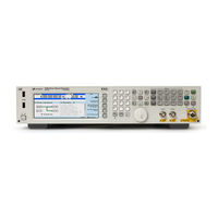
Agilent Technologies E8257C User Manual (220 pages)
PSG Signal Generators
Brand:
Agilent Technologies
| Category:
Inverter
| Size: 2.41 MB
Table of Contents
Table of Contents
3
Signal Generator Overview
11
Signal Generator Models and Features
12
E8247C PSG CW Signal Generator Features
12
E8257C PSG Analog Signal Generator Features
13
E8267C PSG Vector Signal Generator Features
14
Options
14
Firmware Upgrades
14
Modes of Operation
15
Front Panel
16
Display
17
Softkeys
17
Knob
17
Amplitude
17
Frequency
17
Save
17
Recall
17
Trigger
18
Menus
18
Help
18
Ext 1 Input
18
Ext 2 Input
19
Lf Output
19
Mod On/Off
19
Alc Input
19
RF On/Off
19
Numeric Keypad
19
Rf Output
20
Sync out
20
Video out
20
Line Power LED
20
Power Switch
20
Standby LED
20
Incr Set
20
Gate/Pulse/Trigger Input
20
Arrows
21
Hold
21
Return
21
Display Contrast Decrease
21
Display Contrast Increase
21
Local
21
Preset
21
I/Q Inputs
22
Data Input
22
Data Clock Input
22
Symbol Sync Input
22
Front Panel Display
23
Active Entry Area
23
Frequency Area
23
Annunciators
24
Digital Modulation Annunciators
26
Amplitude Area
26
Error Message Area
26
Text Area
26
Softkey Label Area
26
Rear Panel
27
AC Power Receptacle
28
Gpib
28
Auxiliary Interface
28
Lan
28
Stop Sweep In/Out
29
Z-Axis Blank/Mkrs
29
Sweep out
29
Trigger out
29
Trigger in
29
Source Settled
29
Event 1
30
Event 2
30
Pattern Trig in
30
Burst Gate in
30
Auxiliary I/O
31
Digital Bus
32
Wideband I Input
32
Wideband Q Input
32
Coh (Coherent Carrier Output)
32
I out
32
I-Bar out
33
Q out
33
Q-Bar out
33
Baseband Gen Ref in
33
Smi (Source Module Interface)
34
Mhz out
34
Mhz in
34
Mhz EFC (Option UNR)
34
Basic Operation
35
Using Table Editors
36
Table Editor Softkeys
37
Modifying Table Items in the Data Fields
37
Configuring the RF Output
38
Configuring a Continuous Wave RF Output
38
Configuring a Swept RF Output
41
Using Ramp Sweep (Option 007)
47
Extending the Frequency Range with a MM-Wave Source Module
57
Modulating a Signal
60
Turning on a Modulation Format
60
Applying a Modulation Format to the RF Output
61
Using Data Storage Functions
62
Using the Memory Catalog
62
Using the Instrument State Register
64
Enabling Options
67
Enabling a Software Option
67
Optimizing Performance
69
Selecting ALC Bandwidth
69
To Select an ALC Bandwidth
69
Using External Leveling
70
To Level with Detectors and Couplers/Splitters
70
To Level with a MM-Wave Source Module
73
Creating and Applying User Flatness Correction
74
Creating a User Flatness Correction Array
74
Creating a User Flatness Correction Array with a MM-Wave Source Module
79
Adjusting Reference Oscillator Bandwidth (Option UNR)
86
To Select the Reference Oscillator Bandwidth
86
To Restore Factory Default Settings
86
Analog Modulation
87
Analog Modulation Waveforms
88
Configuring am
89
To Set the Carrier Frequency
89
To Set the RF Output Amplitude
89
To Set the am Depth and Rate
89
To Turn on Amplitude Modulation
89
Configuring FM
90
To Set the RF Output Frequency
90
To Set the RF Output Amplitude
90
To Set the FM Deviation and Rate
90
To Activate FM
90
Configuring M
91
To Set the RF Output Frequency
91
To Set the RF Output Amplitude
91
To Set the FM Deviation and Rate
91
To Activate FM
91
Configuring Pulse Modulation
92
To Set the RF Output Frequency
92
To Set the RF Output Amplitude
92
To Set the Pulse Period and Width
92
To Activate Pulse Modulation
92
Configuring the LF Output
93
To Configure the LF Output with an Internal Modulation Source
94
To Configure the LF Output with a Function Generator Source
95
Dual Arbitrary Waveform Generator
97
Arbitrary (ARB) Waveform File Headers
98
Creating a File Header for a Modulation Format Waveform
99
Modifying Header Information in a Modulation Format
100
Storing Header Information for a Dual ARB Player Waveform Sequence
105
Modifying and Viewing Header Information in the Dual ARB Player
105
Playing a Waveform File that Contains a Header
108
Using the Dual ARB Waveform Player
109
Accessing the Dual ARB Player
109
Creating Waveform Segments
110
Building and Storing a Waveform Sequence
111
Playing a Waveform
112
Editing a Waveform Sequence
112
Storing and Loading Waveform Segments
113
Renaming a Waveform Segment
113
Using Waveform Markers
114
To Place a Marker at the First Point Within a Waveform Segment
114
To Place a Marker Across a Range of Points Within a Waveform Segment
114
To Place Repetitively Spaced Markers Within a Waveform Segment
115
To Use Marker 2 to Blank the RF Output
115
To Toggle Markers in an Existing Waveform Sequence
116
To Toggle Markers as You Create a Waveform Sequence
117
To Verify Marker Operation
117
Waveform Marker Concepts
118
Using Waveform Triggers
121
To Use Segment Advance Triggering
121
Using Waveform Clipping
122
To Configure Circular Clipping
122
To Configure Rectangular Clipping
122
Waveform Clipping Concepts
123
Custom Arb Waveform Generator
129
Overview
130
Working with Predefined Setups (Modes)
131
Selecting a Custom ARB Setup or a Custom Digital Modulation State
131
Working with User-Defined Setups (Modes)-Custom Arb Only
132
Modifying a Single-Carrier NADC Setup
132
Customizing a Multicarrier Setup
133
Recalling a User-Defined Custom Digital Modulation State
134
Working with Filters
135
Using a Predefined FIR Filter
136
Using a User-Defined FIR Filter
137
Working with Symbol Rates
143
To Set a Symbol Rate
143
To Restore the Default Symbol Rate (Custom Real Time I/Q Only)
143
Working with Modulation Types
146
To Select a Predefined Modulation Type
146
To Use a User-Defined Modulation Type (Real Time I/Q Only)
147
Configuring Hardware
153
To Set a Delayed, Positive Polarity, External Single Trigger
153
To Set the ARB Reference
154
Custom Real Time I/Q Baseband
155
See also
155
Overview
156
Working with Predefined Setups (Modes)
156
Selecting a Predefined Real Time Modulation Setup
156
Deselecting a Predefined Real Time Modulation Setup
156
Working with Data Patterns
157
Using a Predefined Data Pattern
158
Using a User-Defined Data Pattern
159
Using an Externally Supplied Data Pattern
162
Working with Burst Shapes
163
Configuring the Burst Rise and Fall Parameters
164
Using User-Defined Burst Shape Curves
165
Configuring Hardware
168
To Set the BBG Reference
168
To Set the External DATA CLOCK to Receive Input as Either Normal or Symbol
169
To Set the BBG DATA CLOCK to External or Internal
169
To Adjust the I/Q Scaling
169
Working with Phase Polarity
170
To Set Phase Polarity to Normal or Inverted
170
Working with Differential Data Encoding
170
Understanding Differential Encoding
170
Using Differential Encoding
175
Multitone Waveform Generator
179
Overview
180
Creating, Viewing, and Optimizing Multitone Waveforms
181
To Create a Custom Multitone Waveform
181
To View a Multitone Waveform
182
To Edit the Multitone Setup Table
183
To Minimize Carrier Feedthrough
185
To Determine Peak to Average Characteristics
187
Two-Tone Waveform Generator
189
Overview
190
Creating, Viewing, and Modifying Two-Tone Waveforms
191
To Create a Two-Tone Waveform
191
To View a Two-Tone Waveform
192
To Minimize Carrier Feedthrough
194
To Change the Alignment of a Two-Tone Waveform
196
Troubleshooting
197
RF Output Power Problems
199
RF Output Power too Low
199
The Power Supply Has Shut down
199
Signal Loss While Working with a Mixer
200
Signal Loss While Working with a Spectrum Analyzer
202
No Modulation at the RF Output
203
Sweep Problems
204
Sweep Appears to be Stalled
204
Cannot Turn off Sweep Mode
204
Incorrect List Sweep Dwell Time
205
List Sweep Information Is Missing from a Recalled Register
205
Data Storage Problems
206
Registers with Previously Stored Instrument States Are Empty
206
Saved Instrument State, but Register Is Empty or Contains Wrong State
206
Cannot Turn off Help Mode
207
Signal Generator Locks up
208
Fail-Safe Recovery Sequence
208
Error Messages
210
Error Message File
210
Error Message Format
211
Error Message Types
212
Returning a Signal Generator to Agilent Technologies
213
Agilent Technologies E8257C Programming Manual (198 pages)
PSG Signal Generators
Brand:
Agilent Technologies
| Category:
Portable Generator
| Size: 2.18 MB
Table of Contents
Table of Contents
3
Getting Started
7
Introduction to Remote Operation
8
Interfaces
9
IO Libraries
9
Programming Language
10
Using GPIB
10
Installing the GPIB Interface Card
10
Selecting IO Libraries for GPIB
12
Setting up the GPIB Interface
12
Verifying GPIB Functionality
13
GPIB Interface Terms
13
GPIB Function Statements
14
Using LAN
18
Selecting IO Libraries for LAN
18
Setting up the LAN Interface
18
Verifying LAN Functionality
20
Using VXI-11
22
Using Sockets LAN
23
Using TELNET LAN
23
Using FTP
26
Using RS-232
28
Selecting IO Libraries for RS-232
28
Using
28
Setting up the RS-232 Interface
29
Verifying RS-232 Functionality
30
Character Format Parameters
30
If You Have Problems
31
Error Messages
31
Error Message File
31
Error Message Types
32
Programming Examples
33
Using the Programming Examples
34
Programming Examples Development Environment
34
Running C/C++ Programming Examples
35
GPIB Programming Examples
36
Before Using the Examples
36
Interface Check Using Agilent BASIC
37
Interface Check Using NI-488.2 and C
38
Interface Check Using VISA and C
39
Local Lockout Using Agilent BASIC
40
Local Lockout Using NI-488.2 and C
42
Queries Using Agilent BASIC
43
Queries Using NI-488.2 and C
45
Queries Using VISA and C
48
Generating a CW Signal Using VISA and C
50
Generating an Externally Applied AC-Coupled FM Signal Using VISA and C
52
Generating an Internal AC-Coupled FM Signal Using VISA and C
55
Generating a Step-Swept Signal Using VISA and C
57
Saving and Recalling States Using VISA and C
58
Reading the Data Questionable Status Register Using VISA and C
61
Reading the Service Request Interrupt (SRQ) Using VISA and C
66
Using 8757D Pass-Thru Commands
71
LAN Programming Examples
74
Before Using the Examples
74
VXI-11 Programing
74
Programming Using SICL in C
74
VXI-11 Programming Using VISA in C
77
Sockets LAN Programming Using C
79
Setting Parameters and Sending Queries Using Sockets and C
81
Sockets LAN Programming Using PERL
107
Setting the Power Level and Sending Queries Using PERL
108
Sockets LAN Programming Using Java
109
Generating a CW Signal Using Java
109
RS-232 Programming Examples
112
Before Using the Examples
112
Interface Check Using Agilent BASIC
112
Interface Check Using VISA and C
113
Queries Using Agilent BASIC
115
Queries Using VISA and C
116
Programming the Status Register System
119
Overview
120
Status Register Bit Values
123
Accessing Status Register Information
124
Determining What to Monitor
124
Deciding How to Monitor
125
Status Register SCPI Commands
127
Status Byte Group
129
Status Byte Register
130
Service Request Enable Register
131
Status Groups
132
Standard Event Status Group
133
Standard Operation Status Group
135
Baseband Operation Status Group
138
Data Questionable Status Group
141
Data Questionable Power Status Group
144
Data Questionable Frequency Status Group
147
Data Questionable Modulation Status Group
150
Data Questionable Calibration Status Group
153
Downloading and Using Files
157
Types of Memory
158
Downloading ARB Waveform Data
159
Data Requirements and Limitations
160
Downloading Waveforms
161
Loading and Playing a Downloaded Waveform
176
Troubleshooting ARB Waveform Data Download Problems
177
Understanding ARB Waveform File Composition and Encryption
178
Downloading Waveform Data to the PSG for Extraction as an Encrypted Waveform File
178
Extracting Waveform Files from the PSG for Use in Other Psgs
179
Downloading Encrypted Waveform Files to the PSG
179
Downloading User File Data
180
Data Requirements and Limitations
181
Bit and Binary Directories
182
Selecting Downloaded User Files as the Transmitted Data
184
Troubleshooting User File Download Problems
184
Downloading FIR Filter Coefficients
185
Data Requirements and Limitations
185
Downloading FIR Filter Coefficients
186
Selecting a Downloaded User FIR Filter as the Active Filter
187
Troubleshooting FIR Filter Coefficient File Download Problems
187
Downloading Directly into Pattern RAM (PRAM)
188
Preliminary Setup
188
Data Requirements and Limitations
189
Downloading in List Format
190
Downloading in Block Format
191
Modulating and Activating the Carrier
192
Viewing a PRAM Waveform
192
Troubleshooting Direct PRAM Download Problems
192
Advertisement
Agilent Technologies E8257C Manual (48 pages)
Series A, B, X Signal Generators
Brand:
Agilent Technologies
| Category:
Inverter
| Size: 0.75 MB
Table of Contents
Table of Contents
5
2 Contacting Agilent Sales and Service Offices
7
3 Products Covered by this Document
9
Document Purpose
10
Recommended Software Upgrades
11
4 Security Terms and Definitions
13
5 Instrument Memory & Volatility
15
MXG (Series B) & EXG Memory
16
MXG (Series A) Memory
19
ESG and PSG Memory
23
6 Memory Clearing, Sanitization and Removal Procedures
29
Erase All
30
Erase and Overwrite All
31
Erase and Sanitize All
32
Force Internal to SD Card
33
Clear Persistent State Information
34
Persistent State
34
Instrument Setup
34
LAN Setup
34
User IQ Cal File (Vector Models Only)
34
Note
35
7 Using Secure Mode
35
Caution
36
8 Using Secure Display
37
9 Security Issues for Certain Firmware Revisions
39
Firmware Update Procedure
39
E8663B
39
Error Messages and Secure Environments
40
Recovering Erased System Files
41
10 Procedure for Declassifying a Faulty Instrument
43
Appendix A. References
47
Agilent Technologies E8257C Installation Manual (36 pages)
PSG Signal Generators
Brand:
Agilent Technologies
| Category:
Portable Generator
| Size: 0.51 MB
Table of Contents
Table of Contents
3
Safety Information
5
Instrument Markings
5
Warnings, Cautions, and Notes
6
General Safety Considerations
6
Getting Started
7
Checking the Shipment
8
Meeting Electrical and Environmental Requirements
9
Environment
9
Ventilation
9
Line Settings
10
Connecting the AC Power Cord
10
AC Power Cord Localization
11
Configuring Global Settings
12
Adjusting the Display
12
Configuring for Remote Control
14
GPIB Interface Configuration
14
LAN Interface Configuration
14
RS-232 Interface Configuration
15
Ordering Accessories
16
Front Handles and Rack Mount Flanges
16
PSG Documentation
16
Proper Usage and Cleaning
18
Cleaning Suggestions
18
Contacting Agilent Technologies
19
Returning a Signal Generator to Agilent Technologies
20
Operation Verification
21
Performing a Self-Test
22
Self-Test Failure
23
Checking the Maximum Leveled Power
24
Maximum Leveled Power Check Failure
24
Checking the Output Power
26
Problems with Output Power
29
Regulatory Information
31
Declaration of Conformity
32
Statement of Compliance
33
Advertisement
Related Products
Agilent Technologies E8257D/67D
Agilent Technologies E8257C PSG
Agilent Technologies E8257D PSG
Agilent Technologies E8257D
Agilent Technologies E8257N
Agilent Technologies E8257Db
Agilent Technologies E8267D PSG
Agilent Technologies E8267D
Agilent Technologies E8267C
Agilent Technologies E8247C
Agilent Technologies Categories
Measuring Instruments
Laboratory Equipment
Test Equipment
Water Pump
Power Supply
More Agilent Technologies Manuals
Login
Sign In
OR
Sign in with Facebook
Sign in with Google
Upload manual
Upload from disk
Upload from URL