Sign In
Upload
Manuals
Brands
Agilent Technologies Manuals
Measuring Instruments
8594E
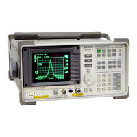
Agilent Technologies 8594E Manuals
Manuals and User Guides for Agilent Technologies 8594E. We have
1
Agilent Technologies 8594E manual available for free PDF download: Service Manual
Agilent Technologies 8594E Service Manual (673 pages)
8590 E-Series and 8590 L-Series
Brand:
Agilent Technologies
| Category:
Measuring Instruments
| Size: 11.55 MB
Table of Contents
Table of Contents
8
Introduction
12
The 8590 Series Analyzers Assembly-Level Repair Service Guide
13
Service Guide Organization
14
Analyzer Description
15
Firmware Revision Date
17
Firmware Upgrade Kit Ordering Information
17
Reliability Considerations
18
Adjustment Procedures
20
Safety
22
Test Equipment You will Need
22
When a 3335A Source Is Not Available
22
If There Are Abnormal Indications During Adjustment
23
Periodically Verifying Calibration
23
Standard-Value Replacement Components
23
If You Replace or Repair an Assembly
24
Making Adjustments
30
Before You Start
31
1A. Display (with Four Access Holes in Top of Shield)
32
1B. Display (with Eight Access Holes in Top of Shield)
35
Sampler Match
41
3. 10 Mhz Reference
43
4. 10 Mhz Precision Frequency Reference
45
Crystal and LC Bandwidth Filter
48
Cal Attenuator Error
57
Log and Linear Amplifier
62
CAL FREQ Adjustment Routine
67
CAL AMPTD Adjustment Routine
69
10. CAL YTF Adjustment Routine
71
11. CAL MXR Adjustment Routine
76
12. Second Converter
78
Third Converter and Second if Bandpass
84
14. Comb Generator
91
Frequency Response of the 8590L, 8591C, and 8591E
95
Frequency Response of the 8592L/94L, 8593E/94E/95E/96E, and 8594Q
105
Equipment Required
106
17. Time and Date
123
Modulator Offset and Gain for Option 010 or 011
125
Entering External ALC Correction Constants for Option 010 or 011
128
Checking the External ALC for Option 010 or 011
130
Correcting for External ALC Error for Option 010 or 011
134
First lo Distribution Amplifier for Option 009 or 010
138
BITG Power Level for Option 010
141
Tracking Oscillator for Option 010
144
Checking the Absolute Amplitude Accuracy for Option 050
150
Correcting for Absolute Amplitude Accuracy for Option 050
156
Checking the Absolute Amplitude Accuracy for Option 051
159
Correcting for Absolute Amplitude Accuracy for Option 051
170
2A. Making Adjustments: if 3335A Source Not Available
176
Before You Start
177
6A. Cal Attenuator Error
178
7A. Log and Linear Amplifier
185
15A. Frequency Response of the 8590L, 8591C, and 8591E
190
Backing up and Reloading Correction Constants
198
Before You Start
199
Backing up Analyzer Correction Constants
200
Analyzer Initialization
203
Reloading the Correction Constants
206
Instrument Calibration after Reloading the Correction Constants
208
Troubleshooting the Analyzer
214
Before You Start
215
Problems at Instrument Power-Up
218
Troubleshooting an Inoperative Analyzer
220
Troubleshooting the A2 Display Assembly
226
Isolating an RF, LO, IF, or Video Problem
231
Using the Internal Service-Diagnostic Routines
237
Troubleshooting the A16 Processor/Video Board Assembly
248
Troubleshooting the if Section
252
Before You Start
253
Service Equipment You will Need
253
After an Analyzer Repair
254
IF Section Information
254
IF Power-Level Measurement
255
Troubleshooting the A15 Motherboard Assembly
265
Troubleshooting the RF Section
280
Before You Start
281
Service Equipment You will Need
282
After an Analyzer Repair
282
6A. 8590L, 8591C, and 8591E
283
6B. 8592L/94L, 8594Q, and 8593E/94E/95E/96E
286
Replacing Major Assemblies
292
Before You Start
293
Service Equipment You will Need
293
After an Analyzer Repair
294
Removal and Replacement Procedures in this Chapter
294
Instrument Cover
295
A1 Front-Frame Assembly
297
A1A1 Keyboard/Front-Panel Keys
301
A2 Display
302
RF Assembly
307
A3 Front-End Assembly
310
A7 Analog Interface Assembly
317
A8 Power Supply
321
A15 Motherboard and if Extrusion
323
A16 Processor/Video Board and A16A1 Memory Board Assembly
329
A16 Processor/Video Board Firmware Roms
334
A16A1BT1 Battery
336
A17 Memory Card Reader Assembly
338
A25 Counter-Lock Assembly
341
B1 Fan
343
Rear-Frame Assembly
345
If You Have a Problem
348
Contacting Agilent Technologies
349
Check the Basics
350
Calling Agilent Technologies Sales and Service Offices
351
Returning Your Analyzer for Service
354
Assembly Descriptions and Block Diagrams
356
Assembly Descriptions and Block Diagrams
357
RF and lo Section for 8590L, 8591E, and 8591C Spectrum Analyzers
358
RF and lo Section for 8592L, 8593E, 8594E, 8594L, 8594Q, 8595E, and 8596E Analyzers
364
IF Section
372
Analyzer Options and Block Diagrams
392
Analyzer Options and Block Diagrams
393
Option Descriptions
396
Troubleshooting Analyzer Options
407
Tracking Generator 8593E, 8594E, 8595E, 8596E Option 010
409
First lo Distribution Amplifier (LODA) 8593E, 8594E, 8594Q, 8595E, 8596E
418
Option 009
418
Option 190 DVB-C Connection Diagram
432
Option 190 DVB-C Service Menus
433
Major Assembly and Cable Locations
452
Major Assembly and Cable Locations
453
Replaceable Parts
484
Replaceable Parts
485
Ordering Information
486
Standard-Value Replacement Components
496
Component-Level Information Packets
520
Softkey Descriptions
552
Analyzer Messages
612
Interpreting Analyzer Messages
613
Service Equipment and Tools
658
Service Equipment and Tools
659
Recommended Test Equipment
660
Safety and Regulatory Information
666
Safety Considerations
667
Safety Symbols
667
Instrument Markings
668
General Safety Considerations
669
Protection from Electrostatic Discharge
671
Advertisement
Advertisement
Related Products
Agilent Technologies 8590L
Agilent Technologies 8591E
Agilent Technologies 8591C
Agilent Technologies 8594Q
Agilent Technologies 8594L
Agilent Technologies 8595E
Agilent Technologies 8596E
Agilent Technologies 8592L
Agilent Technologies 8593E
Agilent Technologies 8590 Series
Agilent Technologies Categories
Measuring Instruments
Laboratory Equipment
Test Equipment
Water Pump
Power Supply
More Agilent Technologies Manuals
Login
Sign In
OR
Sign in with Facebook
Sign in with Google
Upload manual
Upload from disk
Upload from URL