Sign In
Upload
Manuals
Brands
Agilent Technologies Manuals
Laboratory Equipment
6890 GC
User Manuals: Agilent Technologies 6890 GC Gas
Manuals and User Guides for Agilent Technologies 6890 GC Gas. We have
1
Agilent Technologies 6890 GC Gas manual available for free PDF download: Operating Manual
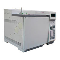
Agilent Technologies 6890 GC Operating Manual (286 pages)
Gas Chromatograph
Brand:
Agilent Technologies
| Category:
Laboratory Equipment
| Size: 2.56 MB
Table of Contents
Table of Contents
3
Chapter 1. The 6890 Series Gas Chromatograph
13
Manuals
14
Control Tables
15
Using Control Tables
16
Some Specifics
18
Gas Control
18
Columns
18
Inlets and Detectors
18
Signals
18
Automation
18
Methods and Sequences
18
Valves
19
Strategy
20
Maintenance Information
21
Fuses and Batteries
21
Maintenance Schedule
22
General Warnings
23
Many Internal Parts of the GC Carry Dangerous Voltages
23
Electrostatic Discharge Is a Threat to GC Electronics
23
Many Parts Are Dangerously Hot
24
Shutting down the GC
25
For Less than One Week
25
For more than One Week
25
Chapter 2. The Keyboard and Display the Display
30
The Status Board
32
The Keyboard
33
Instant Action Keys [Start], [Stop], and [Prep Run]
34
Function Keys
35
Short-Cut Keys [Temp], [Pres], [Flow], [Det Control], [Ramp #]
36
[Temp], [Pres], and [Flow]
36
[Det Control]
37
[Ramp #]
38
[Info]
39
[Status]
40
The Ready/Not Ready Status Table
40
The Setpoint Status Table
41
Procedure: Configuring the Setpoint Status Table
41
Miscellaneous Keys
42
[Time]
42
Procedure: Setting Time and Date
42
Procedure: Using the Stopwatch
43
Procedure: Setting up [Post Run]
43
[Run Log]
44
[Options]
45
[Config]
47
Modifier Keys
48
[Mode/Type]
48
[Clear]
49
[Delete]
49
Storage and Automation
51
Default Parameters
52
Procedure: Loading the Default Parameters
52
Chapter 3. Flow and Pressure Control Hydrogen Shutdown
55
Column Shutdown
55
Turning Gas Flows on and off
56
EPC-Controlled Streams
56
Nonepc-Controlled Streams
56
Part 1. Electronic Pneumatic Control (EPC)
57
Interpreting Flow and Pressure Readings
57
Configuration
58
Columns and Inlets
59
Configure the Column
60
Procedure: Configuring a Capillary Column
61
Additional Notes on Column Configuration
62
Configure the Carrier Gas
63
Procedure: Configuring the Carrier Gas
63
Select a Column Mode
64
The Flow Modes
64
The Pressure Modes
64
Procedure: Selecting a Column Mode
65
Enter the Initial Flow or Pressure or Average Linear Velocity
66
Procedure: Setting Initial Flow or Pressure or Average Linear Velocity
68
Enter a Flow or Pressure Program (Optional)
69
Procedure: Programming Column Pressure or Flow
69
Enter the Rest of the Inlet Parameters
71
Procedure: Setting the Rest of the Inlet Parameters
72
Detectors
74
Gas Configuration
77
Makeup Gas
77
Auxiliary Channels
78
Procedure: Changing an Auxiliary Channel Frit
81
Maintaining EPC Calibration
82
Flow Sensors
82
Pressure Sensors
82
Zero Conditions
82
Procedure: Zeroing Flow and Pressure Sensors
83
Part 2. Nonepc Control
84
Inlets
84
Septum Purge
84
Detectors
85
Internal/External Plumbing: FID and NPD Without EPC
85
Internal/External Plumbing: TCD Without EPC
86
Internal/External Plumbing: ECD Without EPC
86
Part 3. Measuring Flow Rates
88
Measuring Flow Rates with a Bubble Meter
88
Where to Measure Flows
89
Adapters for Measuring Flow Rates
89
Procedure: Measuring Gas Flows with a Bubble Meter
90
Interpreting Flow Meter Measurements
91
Part 4. Flow and Pressure Problems
92
A Gas Does Not Reach the Setpoint Pressure or Flow
92
A Gas Exceeds the Setpoint Pressure or Flow
93
The Inlet Pressure or Flow Fluctuates
93
The Measured Flow Is Not Equal to the Displayed Flow
94
Chapter 4. The Column Oven
95
Oven Capabilities
96
Oven Safety
97
Configuring the Oven
98
Procedure: Setting up an Isothermal Run
99
Making a Temperature-Programmed Run
100
Oven Temperature Programming Setpoints
101
Oven Ramp Rates
102
Procedure: Setting up a Single-Ramp Program
103
Procedure: Setting up a Multiple-Ramp Program
104
Fast Chromatography
105
Fast-Heating Oven
105
Configuring the Oven
105
Using the Oven Insert for Fast Chromatography
106
To Install the Oven Insert
106
Removing the Insert
108
Cryogenic Operation
109
Cryogenic Control Setpoints
109
Chapter 5. Columns and Traps
111
Part 1. Capillary Columns
112
Column Hanger
112
Procedure: Preparing Capillary Columns
113
Procedure: Installing Capillary Columns in the Split/Splitless Inlet
115
Procedure: Installing Capillary Columns in the Cool On-Column Inlet
117
Procedure: Installing Capillary Columns in the Purged Packed Inlet
118
Procedure: Installing Capillary Columns in the PTV Inlet and Volatiles Interface
121
Procedure: Installing Capillary Columns in NPD and FID Detectors
121
Procedure: Installing Capillary Columns in the TCD
125
Procedure: Installing Capillary Columns in the ECD and Μ-ECD
126
Procedure: Installing Capillary Columns in the FPD
130
Ferrules for Capillary Columns
133
Graphite and Graphitized-Vespel Ferrules
133
Vespel Ferrules
133
Part 2. Packed Metal Columns
134
Overview: Installing Packed Metal Columns
134
Fittings
135
Preparing Packed Metal Columns
136
Procedure: Making a Spacer from Teflon Tubing
137
Procedure: Installing Ferrules on a Metal Column
139
Procedure: Installing an Adapter in a Detector Fitting
140
Procedure: Installing Packed Metal Columns
141
Ferrules for Packed Metal Columns
142
Part 3. Packed Glass Columns
143
Overview: Installing Glass Packed Columns
143
Procedure: Installing Glass Packed Columns
145
Ferrules and O-Rings for Glass Packed Columns
147
Part 4. Conditioning Columns
148
Procedure: Preliminary Column Conditioning Steps
149
Procedure: Conditioning a Capillary Column
150
Procedure: Conditioning Packed Columns
151
Part 5. Conditioning Chemical Traps
152
Part 6. Calibrating Your Capillary Column (Optional)
153
Calibration Modes
153
Column Calibration Procedures
154
Procedure: Estimate the Actual Column Length or Diameter from an Elution Time
154
Procedure: Estimate the Actual Column Length or Diameter from the Measured Flow Rate
156
Procedure: Estimate the Actual Column Length and Diameter
158
Chapter 6. Signal Handling
161
Using the Signal Control Tables
162
Signal Type
162
Value
162
Analog Output Settings-Zero, Range, and Attenuation
166
Analog Zero
166
Procedure: Zeroing Signal Output
166
Range-For Analog Outputs Only
167
Attenuation-For Analog Outputs Only
168
Data Rates
169
Procedure: Selecting Fast Peaks
169
Digital Data Handling
169
Digital Zero
169
Baseline Level Shifts
169
Chemstation
171
Inet
172
Column Compensation
172
Procedure: Creating a Column Compensation Profile
174
Procedure: Making a Run Using Column Compensation
174
Procedure: Plotting a Stored Column Compensation Profile
176
Test Plot
176
Chapter 7. Instrument Automation
179
Executing Events During the Run
180
Run Time Programming
180
Using Run Time Events
181
Procedure: Programming Run Time Events
182
The Run Table
183
Procedure: Adding Events to the Run Table
183
Procedure: Editing Events in the Run Table
184
Procedure: Deleting Run Time Events
184
Clock Time Programming
185
Using Clock Time Events
186
Procedure: Programming Clock Time Events
186
Procedure: Adding Events to the Clock Table
189
Procedure: Editing Clock Time Events
189
Procedure: Deleting Clock Time Events
190
Chapter 8. Analytical Methods
191
What Is a Method
192
What Can You Do with It
192
Creating a Method
193
Procedure: Storing a Method
194
Procedure: Loading a Previously Stored Method
195
Procedure: Loading the Default Method
196
Method Mismatch
197
User-Entered Configuration Changes
197
Hardware Configuration Changes
197
Procedure: Modifying a Previously Stored Method
198
Procedure: Deleting a Stored Method
199
Method Listings
199
Chapter 9. Valve Control
201
The Valve Box
202
Heating the Valves
202
Valve Temperature Programming
203
Configuring an Aux Thermal Zone
203
Valve Control
204
The Valve Drivers
204
The Internal Valve Drivers
204
The External Valve Drivers
205
Valve Configurations
206
Procedure: Configuring a Valve
207
Valve Control
208
Procedure: Controlling Valves from the Keyboard
208
From the Run or Clock Time Tables
208
Valve Control Examples
209
Simple Valve-Column Selection
209
Gas Sampling Valve
209
Multiposition Stream Selection Valve and Sampling Valve
211
Chapter 10. The Automatic Liquid Sampler
213
Part 1. the 7673 als
214
Injector Control Table
216
Procedure: Editing Injector Setpoints
217
Configuring the Injector
217
Procedure: Configuring the Injector
218
Sample Tray Setpoints
218
Procedure: Editing the Sample Tray Setpoints
218
Procedure: Configuring the Bar Code Reader
219
Storing Injector Setpoints
220
Part 2. the 7683 als
221
Injector Control Table
223
Procedure: Editing Injector Setpoints
224
Configuring the Injector
225
Procedure: Configuring the Injector
226
Sample Tray Setpoints
226
Procedure: Editing the Sample Tray Setpoints
226
Procedure: Configuring the Bar Code Reader
227
Storing Injector Setpoints
227
Chapter 11. Analytical Sequences
229
What Is a Sequence
230
What Can You Do with It
230
Defining a Sequence
232
Priority Sequence
233
Subsequences
233
Post Sequence
234
Procedure: Creating a Sequence
234
Procedure: Creating a Sampler Subsequence
234
Procedure: Creating a Valve Subsequence
235
Procedure: Setting the Post Sequence Events
236
Procedure: Storing a Sequence
237
Procedure: Loading a Previously Stored Sequence
238
Procedure: Modifying a Previously Stored Sequence
239
Procedure: Deleting a Sequence
240
Sequence Control
240
Sequence Status
241
Procedure: Starting/Running a Sequence
241
Procedure: Pausing and Resuming a Sequence
242
Procedure: Stopping a Sequence
242
Aborting a Sequence
243
Special Considerations When Using an Integrator
244
Chapter 12. Messages
245
Not Ready
246
Method Mismatches
246
Warning
247
Shutdown
247
Faults
247
Bad Mainboard and Fatal Error Messages
247
Part 1. Not Ready Messages
249
Temperature Zone Not Ready
252
Pressure And/Or Flow Not Ready
253
Detector Not Ready
253
Valve Not Ready
255
Other Not Ready Messages
256
Part 2. Shutdown Messages
258
Part 3. Warning Messages
264
Part 4. Fault Messages
268
Advertisement
Advertisement
Related Products
Agilent Technologies 6890N
Agilent Technologies 6890A
Agilent Technologies 6890 Plus
Agilent Technologies 6850 Series II
Agilent Technologies 6850 Series
Agilent Technologies 6820
Agilent Technologies 6430
Agilent Technologies 6100 Series
Agilent Technologies 6400 Series
Agilent 6460
Agilent Technologies Categories
Measuring Instruments
Laboratory Equipment
Test Equipment
Water Pump
Power Supply
More Agilent Technologies Manuals
Login
Sign In
OR
Sign in with Facebook
Sign in with Google
Upload manual
Upload from disk
Upload from URL