Sign In
Upload
Manuals
Brands
Advanced Energy Manuals
DC Drives
MDX II
User Manuals: Advanced Energy MDX II DC Drives
Manuals and User Guides for Advanced Energy MDX II DC Drives. We have
1
Advanced Energy MDX II DC Drives manual available for free PDF download: User Manual
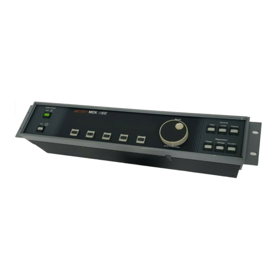
Advanced Energy MDX II User Manual (249 pages)
Brand:
Advanced Energy
| Category:
DC Drives
| Size: 4.98 MB
Table of Contents
Table of Contents
5
Chapter 1. Introduction
15
Read this Section
15
Interpreting the Manual
15
Type Conventions
15
Icons (Symbols)
15
Safety
18
Product Safety/Compliance
18
Directives
18
Table 1-1. Electromagnetic Compatibility (EMC)
18
Table 1-2. Safety Directives
18
Standards
19
Conditions of Use
19
Chapter 2. Product Overview
21
General Description
21
Panels
22
Displays
22
Interfaces
23
Unit Control Hierarchy
24
Output Regulation
25
Theory of Operation
25
Figure 2-1. MDXII Unit Functional Block Diagram
25
Figure 2-2. Switching Theory
26
Figure 2-3. Switching Theory Detail
26
Software Highlights
27
Arc Suppression
27
Fault Conditions and Indicators
27
Halo
28
Programmable Setpoints
28
Tap Settings
28
Target Supervision
28
Timers
29
Unit Software Configuration
29
Identifying Software Versions
29
Identifying Optional Software Features
29
Table 2-1. Hex-Conversion Table
30
Table 2-2. Example Software Options Table
31
Table 2-3. Software Options 7001020 - Expanded Profibus Command Set/Fast User Port
32
Table 2-4. Software Options 7004000 - Standard MDXII Unit
33
Table 2-5. Software Options 7004002 - MDXII Master/Slave Unit
34
Table 2-6. Software Options 7004025 - MDXII Profibus/Fast User
35
Table 2-7. Software Options 7004027 - MDXII Auto Contactor
36
Table 2-8. Software Options 7002218 - Standard MDXII (Universal Logic Card)
37
Table 2-9. Software Options 7002216 - MDXII CE Fast User Port (Universal Logic Card)
38
Understanding the Optional Software Features
39
Custom Options
43
Custom Software
43
Setpoint, 4 Target Software
43
Auto-Contactor Software
44
Custom Hardware
44
Setpoint.D
44
Deko
44
Chapter 3. Specifications
45
Physical Specifications
45
Table 3-1. MDXII 15K and 30K Physical Specifications
45
Electrical Specifications
46
Table 3-2. MDXII 15K and 30K Electrical Specifications
46
Table 3-3. MDXII 15K and 30K Output Voltage/Current Parameters
46
Environmental Specifications
47
Table 3-4. Climatic Specifications
47
Table 3-5. Coolant Parameters for Air (Gas)
47
Chapter 4. Installation
49
Setting up
49
Unpacking
49
Spacing Requirements
50
Figure 4-1. Top and Side Clearance Requirements for MDXII Units Stacked in a Cabinet
50
Figure 4-2. Rear Clearance Requirements for MDXII Units Stacked in a Cabinet
51
Cooling Requirements
52
Figure 4-3. Direction of Air Flow Around an MDXII Unit in a Cabinet
52
Cabinet Design
53
Figure 4-4. Cooling Pattern for Several Units Enclosed in a Cabinet
54
Rear Panel Connections
55
Grounding
55
Input Power Connection
55
Figure 4-5. Connecting the Input
57
Output Power Connection
58
Optimal Output Connection
58
Negative Output
59
Figure 4-6. Two Styles of Cables for Optimal Output Connection
59
Figure 4-7. Connector Wired for Negative Output
60
Positive Output
61
Figure 4-8. Connector Wired for Positive Output
62
Floating Output
63
Junction Box Port
63
Slave Port
63
Other Connections
64
Disconnecting
64
Chapter 5. Operation Overview
65
Output Regulation
65
Power
65
Current
66
Voltage
66
Limits
66
Timers and Counters
66
Ramp Timer
66
Run Timer
66
Output Setpoint Level
67
Out-Of-Setpoint Timer
67
Allowable Setpoint Deviation
68
Steps and Recipes
68
Target Controls
68
Arc Controls
69
Arc Counting Features and Limits
69
Arc Delay and Density
70
Arc Trip Levels
70
Arc-Check
70
Tap Settings
71
Table 5-1. Maximum Tap Setting Voltages and Currents
71
Selecting the Correct Tap
72
Figure 5-2. Impedances Plotted for the Example 1 Target
76
Figure 5-3. Voltage and Current Values for the Example 2 Target out of Range
77
Figure 5-4. Impedances Plotted for the Example 2 Target
78
Power Supply Enhancements
80
Lock
80
Program Source
80
Clicks
81
Serial Port Timeout Value
81
Analog Input Filtering
81
Transductor Calibration
82
Features/Options
82
Ascii
82
Halo
83
Vhalo
84
Contactor Hold
84
Service Functions
85
System Statistics
85
Memo Function
85
Clear NOVRAM
85
Check NOVRAM
85
References to Operation Functions
86
Table 5-1. Operation Reference Table
86
First-Time Operation
91
Chapter 6. Panel Connection, Controls and Indicators
93
Active Remote Panel Connection
93
Figure 6-1. Active Remote Panel Connector
93
Control Panel Interface
94
Output Power Switches
94
Control Switches
94
Regulation Switches
95
Two-Line Display
95
Soft Keys
95
Modify Knob
95
Control Panel Controls
95
Figure 6-2. Control Panel First-Level Menu Functions
96
Figure 6-3. Control Panel Menu Tree
97
Using Limits Functions
98
Using Timers Functions
98
Programming Ramp Time
98
Programming Output Setpoint Level
99
Setting Run Time
100
Setting Out-Of-Setpoint Time
101
Using Target Functions
101
Specifying an Active Target
101
Seeing Which Target Is Active
101
Setting the Target Life
102
Viewing the Remaining Target Life
102
Using Arc Functions
102
Detecting and Counting Arcs
102
Programming Delay and Density
102
Setting Arc Trip Levels
103
Programming Arc-Check
103
Using more Functions
104
Specifying a Tap Setting
104
Locking the Control Panel
104
Specifying Analog Input Filtering
106
Setting the Program Source
106
Specifying Clicks
106
Specifying Serial Port Timeout Value
107
Using the HALO Feature
107
Using the Contactor Hold Feature
107
Using the ASCII Feature
108
Calibrating the Transductor
108
Displaying User Input Character String
108
Returning Stored Parameters to Default State
109
Checking Values Stored in Nonvolatile Memory
109
Obtaining System Statistics
109
Panel Indicators
111
Control Panel LED and Fault Message Indicators
111
Passive Panel LED Indicators
111
Panel Illustrations
111
Figure 6-4. Front View of 15K Stand-Alone Unit with Active Front Panel
112
Figure 6-5. Front View of 15K Stand-Alone Unit with Passive Front Panel
113
Figure 6-6. Rear View of 15K Stand-Alone Unit
114
Figure 6-7. Front View of 30K Stand-Along (or Master) Unit with Active Front Panel
115
Figure 6-8. Front View of 30K Unit with Passive Front Panel
116
Figure 6-9. Rear View of 30K Stand-Alone (or Master) Unit (CE Model Shown)
117
Figure 6-10. Front View of an MDXII Active Remote Panel
118
Figure 6-11. Rear View of an MDXII Active Remote Panel
119
Chapter 7. Serial Port Connection, Controls and Indicators
121
Serial Port Connection
121
Pin Descriptions
122
Figure 7-1. Serial Port Connector
122
Table 7-1. Serial-Port Pin Descriptions
122
Configuration
123
AE Bus or Profibus Operation
123
Figure 7-2. Logic PCB in Card Cage
123
Figure 7-3. Switches, Jumpers, and Connectors on the Logic Board
124
Table 7-2. Configuring for Serial Port Mode of Operation
124
AE Bus Multidrop Operation
125
AE Bus Interface
125
Addresses and Baud Rates
125
Figure 7-4. S1 Switch on the MDXII Rear Panel
125
Table 7-3. Setting AE Bus Network Addresses
126
Table 7-4. Setting AE Bus BAUD Rates
127
Communications Protocol
128
Figure 7-5. Representation of a Message Packet
129
Figure 7-6. Ideal Communications Transaction
131
Figure 7-7. Example Communications Transaction
132
Profibus Interface
133
Addresses and Baud Rates
133
Figure 7-8. S1 Switch on the MDXII Rear Panel
133
Communications Protocol
134
Table 7-5. Configuration of Profibus Download Bytes
134
Table 7-6. Configuration of Profibus Upload Packet
135
Table 7-7. Definitions of Profibus Upload Packet Status Bits
136
Table 7-8. Example .Gsd File for an MDXII Profibus
139
Terminating Profibus
140
Serial Port Controls
140
Table 7-9. AE Bus and Profibus Communications Commands
140
Serial Port Indicators
177
AE Bus Indicators
177
Command Status Response (CSR) Codes
177
Table 7-10. AE Bus Command-Status Response (CSR) Codes
177
Profibus Indicators
178
Profibus-Specific Errors
178
Profibus Watch Dog Timer
178
Profibus-Specific Debug Menu
178
Chapter 8. Troubleshooting and Customer Support
181
Before You Call AE Customer Support
181
Troubleshooting Checklists
181
First Check
181
Checks with the Unit Powered off
181
Checks with the Unit Powered on
182
Checks if the Output Does Not Turn on
183
Checks for General Fault Conditions
183
Table 8-1. General Fault Conditions
183
Status Indicators
184
Panel Leds and Fault Messages
184
Table 8-2. Panel Leds and Fault Messages
185
Serial Port Command-Status Response (CSR) Codes
192
Table 8-3. AE Bus Command-Status Response (CSR) Codes
192
User Port Output Signals
193
Table 8-4. User Port Status Indicators
193
AE Customer Support
194
Table 8-5. Customer Support Locations
194
Returning Units for Repair
195
Warranty
195
Authorized Returns
196
Warranty Statement
196
Chapter 9. User Port Connection, Controls and Indicators
197
User Port Connection
197
Noise Prevention
197
Wiring Options
197
External Monitoring of Output
197
Figure 9-1. User Port Connector
197
Figure 9-2. Wiring for Externally Monitoring the Output
198
External Programming of Ramp Timer and Setpoint
199
Normal Interlock Connection
199
Figure 9-3. Wiring for Externally Programming Ramp Timer and Output Setpoint
199
Figure 9-4. Wiring for a Normal Interlock Setup
199
External On/Off Control for Dual Line Units
200
Figure 9-5. Wiring for External On/Off Control
200
Cheater Plug
201
Figure 9-6. Wiring Diagram for the "Cheater" Plug
201
User Port Grounding
202
User Port Controls and Indicators
202
Signal Pin Descriptions
203
Table 9-1. User Port Signal Pins
203
Table 9-2. Standard User Port Analog Signal Scalings
211
Appendix A. MDXII 18P Unit
213
Specifications
213
Physical Specifications
213
Table A-1. MDXII 18P Physical Specifications
213
Electrical Specifications
214
Table A-2. MDXII 18P Electrical Specifications
214
Table A-3. MDXII 18P Output Voltage/Current Parameters
214
Environmental Specifications
215
Operations and Functions
215
Contactor Closure
215
Deko/Varc
215
Table A-4. MDXII 18P Climatic Specifications
215
Fast User Port
216
Pulsed Duty Cycle Monitor
216
Tap Settings
216
Table A-5. MDXII 18P User Port Scalings
216
Vhalo
217
Table A-6. MDXII 18P Maximum Tap Setting Voltages and Currents
217
18P Unit Illustrations
218
Figure A-1. Active Front Panel of an MDXII 18P Unit
218
Figure A-2. Passive Panel of an MDXII 18P Unit
219
Figure A-3. Rear View of an MDXII 18P Unit
220
Appendix B. Master/Slave
221
Electrical Specifications
221
Table B-1. Electrical Specifications
221
Table B-2. Output Power
222
Table B-3. Output Display Accuracy (Based on 30 Kw Master)
222
Table B-4. Output Display Accuracy (Based on 15 Kw Master)
222
Operations
223
Slave Port
223
Table B-5. Output Parameters
223
Table B-6. Pin Descriptions
223
Indicators
228
Fault Messages
228
Table B-7. LED Descriptions
228
Table B-8. Fault Messages
228
Host/MDXII Communications Commands
230
Table B-9. Communications Commands
230
Figure B-1. Rear View of a 15 Kw Slave
232
Making Rear Panel Connections
233
Setting up for Master/Slave or Stand Alone Operation
233
Figure B-2. Transducer Board Location
233
Figure B-3. DIP Switch Block
234
Running as a Master/Slave System
234
Running as a Stand Alone Supply
235
Figure B-4. Interconnect Cable Connection
236
Start-Up Procedure
237
Master/Slave Operation
237
Table B-10. System Configurations
237
Target Controls
238
Tap Settings
239
Selecting the Correct Tap
239
Table B-11. Output Parameters
239
Advertisement
Advertisement
Related Products
Advanced Energy Paramount MF 2 kW
Advanced Energy LumaSense Technologies E2T QUASAR M8100PM-EXP
Advanced Energy LumaSense Technologies E2T QUASAR M8100FM-EXP
Advanced Energy LumaSense Technologies E2T QUASAR M8100SM-EXP
Advanced Energy Categories
Measuring Instruments
Power Supply
Controller
Portable Generator
Inverter
More Advanced Energy Manuals
Login
Sign In
OR
Sign in with Facebook
Sign in with Google
Upload manual
Upload from disk
Upload from URL