Sign In
Upload
Manuals
Brands
Adtech Manuals
Control Systems
CNC9640
Adtech CNC9640 4-Axis CNC Controller Manuals
Manuals and User Guides for Adtech CNC9640 4-Axis CNC Controller. We have
2
Adtech CNC9640 4-Axis CNC Controller manuals available for free PDF download: Maintenance Manual, Programming Manual
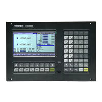
Adtech CNC9640 Maintenance Manual (249 pages)
Brand:
Adtech
| Category:
Control Systems
| Size: 14.45 MB
Table of Contents
Table of Contents
6
1 System Technical Characteristics
12
System Technical Parameters
12
System Operating Condition
14
System Function
14
Self-Diagnosis Function
14
Compensation
14
Abundant Instruction System
14
Full Chinese Menu Operation & Full Screen Edit
15
Abundant Error-Correction Functions
15
Program Exchange between CNC System and PC
15
2 Operating Panel
16
ADTCNC96 Series System Lcd/Keypad
16
ADTCNC99 and 98 Series System Lcd/Keypad
18
System Menus
20
Autorun
20
Program Edit
21
Parameter
22
Work Coordinates
22
Diagnosis
23
Operating Keys
24
3 Manual Operation
26
Returning to Reference Point Manually
26
Each Axis Returns to Reference Point Separately
26
Each Axis Return to Reference Point Simultaneously
26
Reset Machine Tool Position
26
Reset Relative Position Manually
27
Continuous Feeding Manually
27
Single-Step Feeding
28
Single-Step Increment Selection
28
Handwheel Feeding
29
Tool Setting
31
Centered (M Series)
31
Tool Regulator (M Series)
33
Auto Tool Setting Mode
39
Four-Point Centering
39
Calculate the Center of the Circle Using Two Points and Radius
39
Calculate Circle Center Using 3 Points
40
Manual Operation
40
Update the Coordinate System
40
Coordinate Parameter
40
EXT Offset Coordinates
40
Tool Regulator Parameter
42
Tool Setting by Test Cutting (L Series)
43
Data Settings
43
Tool Compensation Data Settings
43
System Parameters Setting
44
System Shortcuts
44
4 Automatic Operation
46
Memory Operation
46
MDI Operation
46
USB Disk DNC
46
Speed Rate Adjustment
47
SBK Function
47
BDT Function
48
Stopping Automatic Operating
48
5 Safe Operation
49
Emergency Stop
49
Hard Limit over Travel
49
Soft Limit over Travel
49
6 Alarm and Self-Diagnosis Function
50
NC Program Execution Alarm Error
50
System Environment Alarm Content Codes
52
Alarm Processing
57
Self-Diagnosis Function
57
7 Program Saving & Editing
58
Saving the Program in the Memory
58
Keypad Input (New Program)
58
Computer Network Access/Serial Port Input
58
Copying Processing Files from USB Disk
62
Reading Programs into Work Area
62
Reading Programs from Controller into Work Area
62
Reading Programs from USB Disk into Work Area
62
Editing & Modifying Programs
63
Single-Line Copy, Paste and Delete
63
Multi-Line Copy, Paste and Delete
63
Macro Function Fast Programming
63
Deleting Files
64
Deleting Files in Memory
64
8 Main Interfaces of the System
65
Position Interface
65
Absolute Position
66
Relative Position
67
Comprehensive Coordinates
68
Deviation Position
68
Edit
69
Program Edit
70
New Program
70
Save as
70
MDI Interface
70
File Management
72
Copy
72
Paste
73
Cut
73
Connect Computer
73
Graphic Simulation
74
Parameter Interface
74
Comprehensive Parameter
76
Axis Parameters
77
Management Parameter
78
Tool Magazine Parameters
79
Spindle Parameters
79
IO Configuration Parameters
80
Compensation Interface
80
Settings of Tool Setting Parameter
83
Allowance
84
Offset
85
Screw Itch Error Compensation
85
Alarm Check
87
IO Diagnosis Interface
87
Function Test
87
System Info
88
Current Mode Instruction Info
89
9 System Maintenance
90
Restart
90
System Upgrade
90
Reset
90
Parameter Backup and Restore
90
Enter BIOS
91
10 System Parameters
92
Parameter Index List
93
Comprehensive Parameter (P1.)
93
Management Parameter (P3.)
110
Tool Magazine Parameter (P4.)
111
Spindle Parameters (P5.)
111
Port Configuration (P6.)
183
11 Hardware Interface Definition and Connection Instructions
187
And 9650 Series External Interface Diagram
188
Series External Interface Diagram
189
Installation Precautions
191
Interface Definition
193
Digital Input Interface
197
Digital Output Interface
203
Handheld Box Interface
207
Analog Output Interface (9640 Series XS8)
210
Spindle Encoder Interface (9640 Series XS12)
211
USB Memory Connection Interface (96 Series XS10)
215
Power Connection Diagram
216
Servo Driver Connection Diagram
217
Step Connection Diagram
218
IO Electrical Connection Diagram
219
ADT9163 Splitter Wiring Diagram
222
ET102A Splitter Wiring Diagram
225
ET202A Splitter Wiring Diagram
228
ADT-I24HNA Input Board
229
12 CNC9 Series Hardware Interface Instructions
232
ADT9163 Splitter Wiring Diagram
235
ET102A Splitter Wiring Diagram
237
ET202A Splitter Wiring Diagram
241
13 Transmission of Computer NC Program Network to the System
244
14 Appendix-Common Servo Wiring Diagrams
248
Advertisement
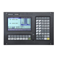
Adtech CNC9640 Programming Manual (161 pages)
Brand:
Adtech
| Category:
Controller
| Size: 3.52 MB
Table of Contents
Table of Contents
5
1 Overview
10
Specification
10
Basic Functions
10
Auxiliary Functions
11
Spindle Functions
11
Tool Functions
12
Gcodes List
12
Program Structure
14
Program Composition
14
Main Program and Subroutine
17
Modal and Non-Modal Function
18
Motion Direction Naming of Control Axes
19
2 System Programming
22
Preparation Functions (Gfunction )
22
G90 G91 Absolute and Relative Programming
22
Rapid Positioning (G00)
23
Linear Interpolation (G01)
24
Arc Interpolation (G02, G03)
25
Pause Instruction (G04)
29
Plane Selection (G17-G19)
29
Machine Tool Coordinate System (G53)
30
Programmable Workpiece Coordinate System (G92)
31
Gfunction Related to Reference Point
32
Auto Return to Reference Point (G28)
32
Auto Return from Reference Point (G29)
34
Reference Point Return Checking (G27)
35
Local Coordinate System (G52)
36
Tool Compensation Gfunction
38
Tool Length Compensation (G43, G44,G49)
38
Tool Radius Compensation (G40, G41, G42)
41
G41/G42Instruction and I, J, K Designation
55
Notes for Tool Radius Compensation
63
Hole Processing Function
67
High-Speed Deep-Hole Drilling Cycle (G73)
72
Left-Hand Thread Tapping Cycle (G74)
73
Fine Boring Cycle (G76)
74
Drilling Cycle (G81)
76
Drilling Cycle, Rough Boring Cycle (G82)
76
Deep-Hole Drilling Cycle (G83)
77
Tapping Cycle (G84)
78
Boring Cycle (G85)
80
Boring Cycle (G86)
81
Back Boring Cycle(G87)
83
Boring Cycle (G88)
84
Boring Cycle (G89)
84
Conversion of Gcommand
88
Program Coordinates Rotation G68 and G69
88
G51.1And G50.1 Mirroring
90
Probe Gcommand
94
G31.1
94
G31.2
94
G31.3
94
Machine Coordinate Positioning Commands
95
G53
95
G53.1
95
3 Auxiliaryfunction
96
Mcode List
96
M00 Program Pause
99
M03 Spindle Moves Clockwise (CW)
99
M04 Spindle Moves Counterclockwise (CCW)
99
M05 Spindle Stops
99
Mcommand for Input Signal Detection Output
99
M88 Input Port Signal Detection
99
M89 Specifies Output Port Control
99
Spindle Speed Functions
100
Tool Function
100
4 Category B Macro Function
101
Variable Instruction
101
Macro Program Call
103
Macro Program Calling Command
103
Variable
107
Types of Variables
109
Calculus Instruction
111
Control Instruction
115
Notes of Using Macro
119
Macro Variable User Parameters System Configuration
119
Extended Special Macro Functions
121
RCOOR Read Workpiece Coordinates
121
RMACPOS Read Machine Tool Coordinates
121
WMACPOS Write Machine Tool Coordinates
121
SPEEDS Set Interpolation Speed
121
SPEEDA Set Positioning Speed
122
MOVEABS Single Axis Moves to the Machine's Position
122
MOVEREL Relative Moved Position of Single Axis
122
MOVEASA Two Axes Move to the Machine's Position (Positioning or Interpolation)
122
MOVERSA Relative Moved Position of Two Axes (Positioning or Interpolation)
123
MOVEASB Three Axes Move to the Machine's Position (Positioning or Interpolation)
123
MOVERSB Relative Position of Motion of Three Axes
123
MOVEASC Absolute Position of Motion of Multiple Axes (Positioning or Interpolation)
124
MOVERSC Relative Position of Motion of Multiple Axes (Positioning or Interpolation)
124
WRITEOUT Write Physical Output
125
WRITELED Write Physical LED
125
READOUT Read Physical Output
125
READIN Read Physical Input
125
READLED Read Physical LED
125
MOVEWAITIN Search and Wait for the Input Signals in Motion
126
M2209
130
M2212
130
M2213
130
M2214
130
M2216
130
M2217
130
M2218
130
M2219
130
M2220
130
M2221
130
M Code Segment Activated by External Input Point
131
Auxiliary Channel Grun 4, 5, 6 and 7
131
Instruction on Custom Cam
132
Overview
132
Introduction of Cam Instruction Interface
132
Cam Instruction Menu Functions
133
Cam Instruction Configuration File
134
Schematic Diagram of Cam Instruction
141
Generation of Processing Programs
145
Cad Dxf Conversion
149
Function
149
Keywords Description
150
Example
151
Dxf File Manual Path Processing
154
Automatic Tool Change (Atc)
157
Spindle
157
Spindle Cabinet
157
Advertisement
Related Products
Adtech CNC9 Series
Adtech CNC9650
Adtech CNC9960
Adtech CNC9816
Adtech CNC9810E
Adtech CNC9810
Adtech CNC Series
Adtech CNC4620
Adtech 4 Series
Adtech ADT-09 Series
Adtech Categories
Transmitter
Control Systems
Control Unit
Controller
Security System
More Adtech Manuals
Login
Sign In
OR
Sign in with Facebook
Sign in with Google
Upload manual
Upload from disk
Upload from URL