Sign In
Upload
Manuals
Brands
ADLINK Technology Manuals
Computer Hardware
cPCI-3970 series
User Manuals: ADLINK Technology cPCI-3970 series Blades
Manuals and User Guides for ADLINK Technology cPCI-3970 series Blades. We have
1
ADLINK Technology cPCI-3970 series Blades manual available for free PDF download: User Manual
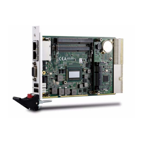
ADLINK Technology cPCI-3970 series User Manual (158 pages)
Performance 3U CompactPCI PlusIO Intel Core i7 Processor Blade
Brand:
ADLINK Technology
| Category:
Computer Hardware
| Size: 9.89 MB
Table of Contents
Revision History
2
Preface
3
Table of Contents
7
List of Figures
11
List of Tables
13
1 Introduction
15
Overview
15
Features
15
Model Number Decoder
16
Package Contents
19
2 Specifications
21
Cpci-3970 Processor Blade Specifications
21
Table 2-1: Cpci-3970 Processor Blade Specifications
21
Cpci-R3P00(T) RTM Specifications
25
Table 2-2: Cpci-R3P00(T) RTM Specifications
25
Block Diagrams
26
Figure 2-1: Cpci-3970 Blade Functional Block Diagram
26
Figure 2-2: DB-3610L2 Daughter Board Func. Block Diagram
27
Figure 2-3: DB-3970L2 Daughter Board Func. Block Diagram
28
Figure 2-4: DB-LANL2-S Daughter Board Func. Block Diagram
29
Figure 2-5: DB-Max Daughter Board Func. Block Diagram
30
Figure 2-6: Cpci-R3P00 RTM Func. Block Diagram
31
Figure 2-7: Cpci-R3P00T RTM Func. Block Diagram
32
I/O Connectivity Table
33
Power Requirements
34
Thermal Requirements
36
3 Functional Description
37
Processors
37
Platform Controller Hub
39
Pmc/XMC
39
Intel® Turbo Boost Technology
40
Intel® Hyper-Threading Technology
40
Trusted Platform Module
40
Battery
41
BIOS Recovery
42
4 Board Interfaces
43
Cpci-3970 Series Board Layout
43
Figure 4-1: Cpci-3970 Series Board Layout
43
Cpci-3970 Blade Assembly Layout
44
Figure 4-2: Cpci-3970 Blade Assembly Layout
44
Cpci-3970D Blade Assembly Layout
45
Figure 4-3: Cpci-3970D Blade Assembly Layout
45
Cpci-3970G Blade Assembly Layout
46
Figure 4-4: Cpci-3970G Blade Assembly Layout
46
Cpci-3970, Cpci-3970D, Cpci-3970G Faceplate
47
Figure 4-5: Cpci-3970(D/G) Front Panel Layout
47
Cpci-3970S, Cpci-3970P, Cpci-3970U Front Panel
48
Figure 4-6: Cpci-3970S/P/U Front Panel Layout
48
Cpci-3970L, Cpci-3970M, Cpci-3970Q Front Panel
49
Figure 4-7: Cpci-3970L/M/Q Front Panel Layout
49
Table 4-1: Cpci-3970 Front Panel System LED Descriptions
50
System Leds
50
Cpci-R3P00(T) RTM Board Layout
51
Figure 4-8: Cpci-R3P00 RTM Board Layout
51
Cpci-R3P00(T) RTM Faceplate
52
Figure 4-9: Cpci-R3P00(T) RTM Front Panel
52
Connector Pin Assignments
53
Table 4-2: USB Pin Definition
53
Table 4-3: VGA Pin Definition
53
Table 4-4: RJ-45 Gbe Pin Definitions
54
Table 4-5: LAN LED Status Definitions
54
Table 4-6: PS/2 Keyboard/Mouse Pin Definition
55
Table 4-7: Cpci-3970D/P COM1 (DB-9) Pin Definition
55
Table 4-8: Cpci-3970D/P COM1 Mode Selection Switch Settings
56
Table 4-9: Cpci-3970G/U COM1 (RJ-45) Pin Definition
57
Table 4-10: Cpci-3970G/U COM1 (DB-9 Adapter) Pin Definition
57
Table 4-11: RS-422/485 Adapter Dongle Pin Definition
58
Table 4-12: Cpci-3970D/P COM1 Dongle Pin Definition
58
Table 4-13: Cpci-3970G/U COM2 Pin Header Definition
59
Table 4-14: Cpci-R3P00 RTM COM4 Pin Definition
59
Table 4-15: Cpci-R3P00(T) RTM COM5 Pin Definition
60
Table 4-16: Cpci-R3P00(T) RTM Com5Dongle Pin Definition
60
Table 4-17: Displayport Pin Definition
61
Table 4-18: Cpci-3970M 100-Pin I/O Connector Pin Definition
62
Table 4-19: Serial ATA Connector on RTM Pin Definition
64
Table 4-20: Serial ATA Connector on DB-3610/3970L2 Pin Def'n
65
Table 4-21: Compactflash Socket Pin Definition
66
Table 4-22: Cfast Socket Pin Definition
67
Table 4-23: DB-3610L2 Connector Pin Definition
68
Table 4-24: DB-3CFAST Connector Pin Definition
69
Table 4-25: DB-3970L2 Connector Pin Definition
70
Table 4-26: DB-3UMC Connector Pin Definition
71
Table 4-27: PMC Connector Pin Definitions
72
Table 4-28: XMC Connector Pin Definition
74
Table 4-29: Compactpci J1 Connector Pin Definition
75
Table 4-30: Compactpci J2 Connector Pin Definition
76
Table 4-31: Cpci-R3P00 Rj2 Connector Pin Definition
77
Table 4-32: Cpci-R3P00T Rj2 Connector Pin Definition
78
Jumper Settings
79
Table 4-33: Load BIOS Default Jumper Settings
79
Table 4-34: XMC VPWR Select Jumper Settings
79
Table 4-35: PMC V(I/O) Select Jumper Settings
79
5 Getting Started
81
CPU and Heatsink
81
Memory Module Installation
82
SATA Drive Installation
84
Compactflash Installation
85
Converting from CF to Cfast Slot
86
PMC/XMC Card Installation
91
Installing the Cpci-3970 to the Chassis
95
RTM Installation - Cpci-R3P00(T)
96
6 Driver Installation
97
Cpci-3970 Drivers
97
USB-To-Serial Converter Driver (RTM)
100
LAN Driver for Cpci-R3P00T
104
7 Utilities
105
Watchdog Timer
105
Figure 7-1: Example Procedure for Configuring the WDT
109
Using the Trusted Platform Module
111
BIOS Recovery
115
BIOS Update
117
8 BIOS Setup Utility
119
Starting the BIOS
119
Main Setup
122
Advanced BIOS Setup
124
Chipset Configuration
134
Boot Configuration
138
Security Setup
139
Save & Exit
140
9 IPMI User Guide
143
Introduction
143
Summary of Commands Supported by BMR-AVR-Cpci
143
OEM Commands Summary Table
147
Compactpci Address Map
151
Communications with IPMC
151
IPMI Sensors List
152
Relevant Documents
153
Important Safety Instructions
155
Getting Service
157
Advertisement
Advertisement
Related Products
ADLINK Technology cPCI-3971 series
ADLINK Technology cPCI-3620 Series
ADLINK Technology cPCI-3510
ADLINK Technology cPCI-3510BLD
ADLINK Technology cPCI-3510BLG
ADLINK cPCI-3510P
ADLINK Technology cPCI-3630 Series
ADLINK Technology NuIPC cPCI-3500A Series
ADLINK Technology NuIPC cPCI-3500A-2S/CB
ADLINK Technology cPCI-3520 Series
ADLINK Technology Categories
Computer Hardware
Motherboard
PCI Card
Control Unit
Single board computers
More ADLINK Technology Manuals
Login
Sign In
OR
Sign in with Facebook
Sign in with Google
Upload manual
Upload from disk
Upload from URL