Sign In
Upload
Manuals
Brands
ABB Manuals
Measuring Instruments
NGC8200
ABB NGC8200 Manuals
Manuals and User Guides for ABB NGC8200. We have
1
ABB NGC8200 manual available for free PDF download: User Manual
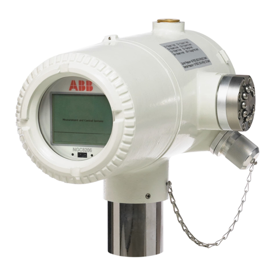
ABB NGC8200 User Manual (137 pages)
Gas Chromatograph
Brand:
ABB
| Category:
Measuring Instruments
| Size: 6.8 MB
Table of Contents
Table of Contents
2
Contents
2
List of Tables
6
Additional Information
7
Compliance
7
Cyber Security
7
Table 0-1: Related Documentation
7
Malware Prevention
8
Waste Electrical and Electronic Equipment (WEEE)
8
Safety
8
Potential Safety Hazards
9
Product Description
10
Overview
10
System Components
10
Principle of Operation: Sample Processing
11
Hardware Description
11
Table 2-1: Analyzer Specifications
11
Analyzer Standard Hardware Features
12
Cast Aluminum Enclosure
13
Exterior Enclosure Dimensions
14
Feed-Through Assembly
16
Configurations
16
Inlets
16
Vents
16
Analytical Module
16
GC Module
17
Analytical Processor/Manifold Assembly
17
Digital Controller Assembly with VGA Display
18
Termination Board
21
Local Communication Options
22
Embedded Software and User Interface
22
Embedded Software
22
User Interface (PCCU32)
22
Audit Quality Data
22
Compressibility Options
23
Calculation Options
23
Engineering Units
23
Supported Communication Protocols
23
Security
24
Installation
24
Plan for Installation
25
Unpack and Inspect
25
Analyzer Installation
25
Pipe Installation for Stand-Alone Mounting
25
Pipe Saddle Installation for Pipe Saddle Mounting
26
Shelf Installation
26
Analyzer Installation
27
Sample System Installation
28
Sample System Design Considerations
28
Tube Quality
28
Maintaining Phase
29
Sample Probe Installation
29
Sample Conditioning Modules
30
Table 4-1: Sample Conditioning Module Descriptions
31
Sample Line Connections
34
Carrier and Calibration System Installation
36
Calibration/Validation Stream
36
Cylinder Rack Installation on Meter Run
36
Carrier Gas Regulator Installation
36
Table 4-2: Calibration Gas Blend Recommended Components
36
Calibration Gas Regulator Installation
37
Carrier Gas and Calibration Gas Line Connections
39
Vent Lines Connections
40
Security Seal
41
Wiring
42
Wire for Serial Communication
42
Wire for Power and Grounding
42
Table 5-1: Serial Port 1 and Port 2 Pinouts and Terminations
42
Power Supply Requirements
43
Operating Voltages and Cable Lengths
43
Other Considerations
44
Ground the Analyzer
44
Cathodic Protection
44
Wire the Analyzer Power Connector
44
Table 5-2: 12 VDC Battery Power Supply System Maximum Cable Lengths
44
Startup
45
Download PCCU32 from the ABB Website
45
Install PCCU32
47
Establish Initial Local Communication
48
Connect Using USB Port (Standard)
48
Table 6-1: Cable for USB Connection
49
Connect Using RS-232 Port
50
Table 6-2: Required Cables for Connection with MMI Port
51
Connect Using Ethernet Port
52
Table 6-3: Ethernet Cabling for Local Connection
53
Power on Sequence
55
Initialization
55
Startup Diagnostics
55
Startup Wizard
57
Set up the Station
59
Set up the Stream
59
Table 6-4: Station Setup Basic Parameters
59
Table 6-5: Stream Setup Screens
60
Set up Calibration
61
View Diagnostics
62
Update Configuration
63
Analyze the Calibration Stream
64
Enable/Disable Streams
66
Run Analysis Process Streams
67
Complete Startup
68
Manual Peak Find
69
Troubleshoot Peak Find
73
Table 6-6: Peak Find Troubleshooting
73
Table 6-7: Suggested Carrier Pressure Setpoint Adjustment Values
74
Calibrate the Analyzer
75
Verify Calibration Data Using Peak Find
78
Configure for Network Connection
79
Basic Topology
79
IP Addressing
80
Cabling for Connection to Network
80
Table 8-1: Ethernet Cabling for Network Connection
80
Enable Ethernet and Configure IP Parameters
81
Verify Network Connection
83
Basic Ethernet Connection Troubleshooting
84
Configure Security
84
Configure Bi-Level Security
85
Table 9-1: Security Guidelines
85
Table 9-2: Bi-Level Security
85
Configure Role Base Access Control (RBAC)
88
Default Access Roles
90
Set up and Create a New RBAC Security Control File
91
Create the Administrator Account
91
Create Additional User Accounts with Standard Roles
93
Save RBAC Configuration File
94
Save Security Configuration on the Device
95
Maintenance
97
Maintaining Cleanliness
97
Visual Inspection
97
Technical Support and Returns
98
Spare Part Components
98
Replacement Components
98
Replacement Parts
98
Spare Parts
100
Field Tool Kit
100
Table 10-1: Spare Parts
100
Back up Configuration Files
101
Update Embedded Software
101
Table 10-2: Field Tools
101
Restore Configuration Files
104
Reset Procedures
105
Warm Start
105
Cold Start
106
Restore Factory Defaults
107
Lithium Battery Status
108
Change the Clock
108
Clock Change Not Crossing a Log Period Boundary
108
Forward Clock Change Crossing a Log Period Boundary
108
Backward Clock Change Crossing a Log Period Boundary
109
Replace Calibration or Carrier Gas Cylinder(S)
109
Replace the Digital Controller Assembly
109
Replace the Digital Controller Complete Assembly
110
Replace the Analytical Module
111
Replace the GC Module
113
Replace the Termination Panel
114
Replace the Feed-Through Assembly
116
Replace the Lithium Battery
117
Replace Frit Filters
118
Replace the Feed-Through Interface Gasket
119
Replace the Feed-Through Manifold Gasket
120
Replace the Termination Panel to the Digital Controller Cable
121
Replace the Analytical Processor to the Termination Panel Cable
122
Troubleshooting
123
Startup Diagnostics Troubleshooting
123
Carrier Pressure Regulator Test
123
Table 11-1: Startup Diagnostics
123
Table 11-2: Carrier Pressure Regulator Diagnostics
123
Oven Temperature Test
124
Processor Control Test
124
Stream Test
124
Table 11-3: Stream Test Diagnostics
124
Troubleshooting Alarms
125
Table 11-4: Default Alarms
125
Table 11-5: Alarm Severity
125
Alarm Definitions
126
Pressure Regulator 1 or 2 Alarm
126
Table 11-6: Default Alarm Definitions
126
Sample Pressure Alarm
127
Oven Temperature Error Alarm
127
No Stream Valve Selected
127
Digital-Analog Board Communication Error Alarm
128
Calculation Error Alarm
128
Calibration Un-Normalized Error Alarm
128
Stream Sequence Error Alarm
128
Calibration CV Percent Error Alarm
128
Calibration RF Percent Error Alarm
129
Enclosure Temperature Alarm
129
Power Supply Alarm
129
Low Carrier Gas Cylinder (DI1) Alarm
130
Low Cal Gas Cylinder (DI2) Alarm
130
GCM Processing Error Alarm
130
Bad Bead Alarm
130
No Pilot Valve Change Detected Alarm
130
Sample Flow Detection Alarm
130
CPU Loading Alarm
131
System Memory Available Alarm
131
RAM File Available Alarm
131
FLASH File Available Alarm
131
Missing Peak - Calibration Not Used
131
Stream Un-Normalized Total
132
Alarm Troubleshooting Tests
132
Column Vent Pressure Test
132
Sample Pressure Test
132
Feed-Through Assembly Blockage Test
133
Temperature Sensor Test
133
Abnormal Calibration Gas Depletion
133
Power Troubleshooting
133
Overview
133
Power Supply Voltage Test
133
Equipment Isolation Test
134
Analyzer Module Isolation Test
134
Serial Communications Troubleshooting
135
Communication
135
Communications Test
135
Table 11-7: RS-232 Field Wiring on Analyzer Termination Panel
135
Table 11-8: RS-485 Terminations
135
Table 11-9: RS-485 Pinouts (on Termination Panel)
135
Advertisement
Advertisement
Related Products
ABB NGC8206
ABB NETA-21
ABB Navigator 600 Series
ABB Navigator 500 Series
ABB Navigator 600 Phosphate
ABB +N5600
ABB NE810
ABB NBRA-654
ABB NAL Series
ABB NSK5
ABB Categories
Industrial Equipment
Controller
Measuring Instruments
Battery Charger
DC Drives
More ABB Manuals
Login
Sign In
OR
Sign in with Facebook
Sign in with Google
Upload manual
Upload from disk
Upload from URL