Sign In
Upload
Manuals
Brands
ABB Manuals
DC Drives
DCS 400
ABB DCS 400 Manuals
Manuals and User Guides for ABB DCS 400. We have
1
ABB DCS 400 manual available for free PDF download: Manual
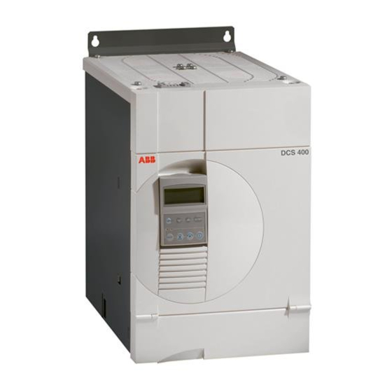
ABB DCS 400 Manual (193 pages)
DCS Thyristor power converter for DC drive systems 20 to 1000 A 9 to 522 kW
Brand:
ABB
| Category:
DC Drives
| Size: 8.12 MB
Table of Contents
Table of Contents
2
List of Contents
2
1 DCS 400 - the Compact-Size DC Drive
3
Unit Functions
4
Monitoring Functions
4
Activation and Operator-Control
4
Drive Window Light
4
2 System Overview of DCS 400
5
Environmental Conditions
6
Current Reduction to (%) for Armature Circuit and Field Supply
6
Compliance with Standards
6
DCS 400 Power Converter Modules
7
Sizes
7
Unit Table
7
DC Voltage Characteristic
7
DCS 400 Overload Withstand Capability
8
Types of Load
8
Load Cycles of Driven Machines
8
Recommended Converter Type
8
Control and Display Units of the DCS 400
9
Possibilities of Operation
9
Operation by PC
10
Start-Up Wizard
10
Example for a Start-Up Wizard Display
10
3 Technical Data
11
Module Dimensions
11
Cross-Sectional Areas - Tightening Torques
13
Cross-Sectional Areas for UL Installations
14
Power Losses
15
DCS 400 Armature Circuit
15
DCS 400 Field Supply
15
Power Section Cooling
16
Fan Data for DCS 400 (Data Per Fan)
16
Monitoring the DCS 400 Power Section
16
Control Board SDCS-CON-3A
17
Control Functions (Watchdog)
17
Supply Voltage Monitoring
17
Seven Segment Display
17
Digital and Analogue I/O Connection of the SDCS-CON-3A
18
Terminal Connection of the SDCS-CON-3A Board
18
Power Interface Board SDCS-PIN-3A
19
AC Supply Voltage (X98:3-4)
19
Output X98:1-2 (DO5)
19
Layout of the SDCS-PIN-3A Board
19
Field Exciter SDCS-FIS-3A
20
Electrical Data of SDCS-FIS-3A
20
Diagram of the Field Exciter Unit
20
Circuit Diagrams
22
Circuit Diagram 4-Q Converter
22
Circuit Diagram 2-Q Converter
23
4 Overview of Software
25
General Information about Application Macros
26
Overview of Factory Settings of Macro-Dependent Parameters
27
Application Macros
28
Description of I/O’s Functionality
30
Inter Locking of Jog Speed 1 – Jog Speed 2 – Drive START
30
Macro 1 - Standard
30
Connection Example Application-Macro 1 - Standard
31
Selection of Speed Reference or 2 Fixed Speed Via DI7 and DI8
32
Connection Example Application-Macro 2 - Man/Const Sp
33
Connection Example Application-Macro 3 - Hand/Auto
35
Connection Example Application-Macro 4 - Hand/Motpot
37
Connection Example Application-Macro 5 - Jogging
39
Connection Example Application-Macro 6 - Motor Pot
41
Connection Example Application-Macro 7 - Ext Field Rev
43
Connection Example Application-Macro 8 - Torque Ctrl
45
Digital and Analogue Inputs/Outputs
46
Comparison Regarding the Accuracy between the Different Control Modes
47
DCS400 Accuracy
47
Drive Logic
48
Switching off Behaviour at Emergency Stop
48
Switching off with Emergency Stop
48
Switching on and off
48
Field Heating
49
Special Cases
49
Switch-On Sequence of DCS 400
49
Minimal Circuitry for the Drive Logic
50
Switch-Off Sequence of DCS 400
50
Monitoring the Mains Voltage and Auto Reclosing
51
Regulator Functions
51
Alarm Trip Threshold
52
Monitoring the Mains Voltage
52
Auto Reclosing
53
Monitoring the Actual Speed Value
53
Automatic Field Weakening
54
Calculated EMF
54
Correlation of Armature Voltage and EMF
54
Motor Name Plate
54
Overtemperature Protection
55
With Speed-Dependent Current Limiting
55
Without Speed-Dependent Current Limiting
55
Armature Current Controller
56
Second Current Limitation
56
Armature Current Controller Operating Modes
57
Alternative Parameters for the Speed Controller
60
Flux Adaptation
60
Stall Protection
60
Autotuning
61
Manual Tuning
61
Service Procedures, Contr Service
61
Speed Controller
62
Thyristor Diagnosis
62
Internal Scaling
63
Signal "At Set Point"
64
Signal "Comm Fault"
64
Signal "Overtemp Mot" / "Overtemp DCS"
64
Signal Definitions
64
User Events
65
Software Structure
66
Parameter List
68
Parameter Overview
68
5 Installation
101
Incoming Inspection
101
Rating Plate
101
Storage and Transport
101
Electrical Connection
102
Intended Use
102
Safety Instructions
102
Transport, Storage
102
Common Warnings
103
EMC Compliant Installation and Configuration for a Power Drive System
104
Earth Fault Detection
105
Filter in an Earthed Line (TN or TT Network)
105
High Voltage Test
105
Classification
106
EMC Classification Guideline
106
Connection of Single and Three Phase Filters
107
Three-Phase Filters
107
Required Minimum Line Choke Impedance for Installation of Converter in First Environment
108
Cabinets
109
Converter (Dedicated) Transformers
109
Installation Hints
109
Separation Transformers
109
Power Cables with Screens
110
Screening
110
Signal Cables
110
Placement of Cables Outside the Cabinet
111
Placement of Cables Within the Cabinet
111
Power Cables Without Screens
111
Fast Fuses
113
Fuses at the Stubs from the Low Voltage Line
113
Industrial Low Voltage Lines
113
Stub for Auxiliary Devices
113
Connection Example in Compliance with EMC
115
Connection Example for Digital and Analogue Coupling of a PLC
117
Connection Examples
117
Connection Example with DC Breaker and Drive Coasting
121
Connection Example for Motor Fan and Converter Fan (Useful for All Macros)
122
6 Operating Instructions
123
Operating Panel DCS 400 PAN
123
OUPUT Display
123
Panel Link
123
Panel Mode: Menu Selection
124
Panel Mode: Function Selection
125
Panel Mode: Parameter Programming
125
Copy to Drive
127
Copy to Panel
127
Factory Setting
127
Panel Lock
127
Actual Value Display
128
Change Reference
128
Drive Control from the Panel
128
Panel Mode: Drive Control
128
Guided Commissioning
129
Parameter Entries
130
Value Parameters Are Parameters with Numerical
130
Start of Guided Commissioning
131
Manually Commissioning
139
Useful Hints for Commissioning
142
Drive Accelerates to Overspeed
143
Hints for Speed Controller Autotuning
143
Oscillating Speed
143
Speed Autotuning Failed
143
Change Macro
144
Comments to Flux Optimisation
144
Gear Protection
144
Motor Drifts at Zero Speed Reference
144
Soft Network in Regenerative Mode
145
Display of Status, Alarm and Fault Signals
146
General Messages
146
Starting Errors
146
Troubleshooting
146
Significance of the Panel Leds
147
Fault Signals (F)
148
Alarm Signals (A)
152
Diagnostic Messages
155
7 Serial Interfaces
159
Drive Configuration with Serial Communication
159
Communcation Parameters
162
Control and Status Word Allocation
163
Telegram Structure
163
Data Set Allocation
164
Panel-Port
164
Status Word Allocation
164
RS232-Port
165
Settings of RS232-Port
165
Connection of a Fieldbus Adapter to DCS 400
166
Fieldbus Interface
166
Short Commissioning Guide
166
Parameter Overview for the most Commonly Used Fieldbuses
167
Devicenet (Including Parameter Transfer)
170
Parameter Settings for the most Commonly Used Fieldbus Adapters
170
DCS 400 Fieldbus Parameter
171
Line Chokes
175
Appendix A Accessories
175
Line Chokes Type ND
176
Line Chokes Type ND 01...ND 06
176
Line Chokes Type ND 07...ND 12
177
Line Chokes Type ND 13
177
Fuses and Fuse Holders for Armature-Circuit Supply
178
Main Dimensions of Fuse Holders
179
EMC Filters
180
Dimensions of Filter
180
B Declaration of Conformity
181
C Quick Installation & Commissioning Guide
182
Application Macro Standard
183
Operation for Armature Control Mode
184
D Examples for Basic Parameter Programming
184
Operation for Field Control Mode
185
Operation for Field Control Mode with Speed-Dependent Current Limiting
186
Common Parameters for the Three Operating Modes
187
Advertisement
Advertisement
Related Products
ABB DCS550 Series
ABB DCS550-S01
ABB DCS800-S01-0125-05
ABB DCS800-S01-0090-05
ABB DCS800-S01-0065-05
ABB DCS800-EP2-0260-05
ABB DCS800-EP2-0075-05
ABB DCS800-S01-0315-05
ABB DCS800-R
ABB +Q950
ABB Categories
Industrial Equipment
Controller
Measuring Instruments
Battery Charger
DC Drives
More ABB Manuals
Login
Sign In
OR
Sign in with Facebook
Sign in with Google
Upload manual
Upload from disk
Upload from URL