AAON RN Series Manuals
Manuals and User Guides for AAON RN Series. We have 7 AAON RN Series manuals available for free PDF download: Installation Operation & Maintenance, Installation, Operation & Maintanance Manual
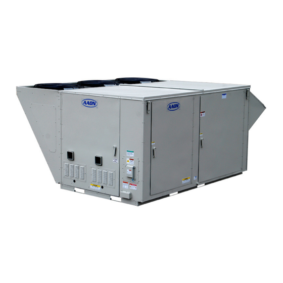
AAON RN Series Installation Operation & Maintenance (136 pages)
Packaged Rooftop Units, Heat Pumps, & Outdoor Air Handling Units
Table of Contents
-
Safety9
-
Installation29
-
Electrical45
-
Startup50
-
Filters50
-
Supply Fans50
-
-
Operation62
-
Maintenance63
-
Options69
-
-
Gas Heating97
-
Piping Supports100
-
Leak Testing104
Advertisement
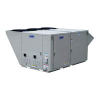
AAON RN Series Installation Operation & Maintenance (136 pages)
Packaged Rooftop Units, Heat Pumps, & Outdoor Air Handling Units
Brand: AAON
|
Category: Air Handlers
|
Size: 12.64 MB
Table of Contents
-
Safety9
-
Storage30
-
Installation31
-
Electrical44
-
Startup50
-
Filters50
-
Supply Fans51
-
Operation67
-
Maintenance68
-
Supply Fans68
-
DX Cooling70
-
Options74
-
Water Piping83

AAON RN Series Installation, Operation & Maintanance Manual (116 pages)
Packaged Rooftop Units, Heat Pumps, & Outdoor Air Handling Units
Table of Contents
-
Safety8
-
Installation29
-
Electrical47
-
Gas Heating50
-
Leak Testing53
-
Startup72
-
Supply Fans72
-
Filters76
-
-
-
Operation83
Advertisement
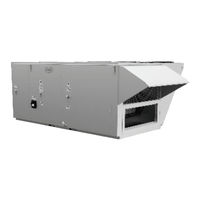
AAON RN Series Installation Operation & Maintenance (120 pages)
Packaged Rooftop Units, Heat Pumps, & Outdoor Air Handling Units
Brand: AAON
|
Category: Heating System
|
Size: 5.21 MB
Table of Contents
-
Safety9
-
Installation29
-
Electrical40
-
Startup45
-
Filters45
-
Supply Fans46
-
-
-
Operation58
-
Maintenance59

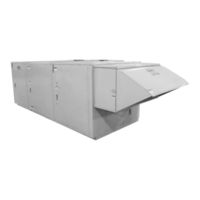
AAON RN Series Installation Operation & Maintenance (108 pages)
Packaged Rooftop Units & Outdoor Air Handling Units
Brand: AAON
|
Category: Air Handlers
|
Size: 6.92 MB
Table of Contents
-
Safety8
-
Storage29
-
Installation29
-
Electrical34
-
Startup40
-
Filters40
-
Supply Fans40
-
Operation50
-
Maintenance51
-
Supply Fans51
-
DX Cooling52
-
Options57
-
Gas Heating76

AAON RN Series Installation Operation & Maintenance (104 pages)
Horizontal Packaged Rooftop Units, Heat Pumps,
& Outdoor Air Handling Units
Table of Contents
-
Safety8
-
Installation28
-
Electrical36
-
Gas Heating39
-
Leak Testing43
-
Startup63
-
Supply Fans63
-
Filters67
-
-
Operation76

AAON RN Series Installation Operation & Maintenance (92 pages)
E Cabinet; Packaged Rooftop Units & Outdoor Air Handling Units
Table of Contents
-
Safety7
-
-
-
Figures
25 -
Installation25
-
Electrical30
-
Storage25
-
Tables
26-
Startup35
-
Filters35
-
Supply Fans35
-
-
Operation41
-
Maintenance42
-
Options46
-
-
Gas Heating65
-
Leak Testing70
-
Advertisement