Table of Contents
Advertisement
Advertisement
Table of Contents

Related Manuals for ECS G31T-M7


Summary of Contents for ECS G31T-M7
- Page 3 Preface Copyright This publication, including all photographs, illustrations and software, is protected under international copyright laws, with all rights reserved. Neither this manual, nor any of the material contained herein, may be reproduced without written consent of the author. Version 1.0 Disclaimer The information in this document is subject to change without notice.
-
Page 4: Declaration Of Conformity
Declaration of Conformity This device complies with part 15 of the FCC rules. Operation is subject to the following conditions: • This device may not cause harmful interference, and • This device must accept any interference received, including interfer- ence that may cause undesired operation Canadian Department of Communications This class B digital apparatus meets all requirements of the Canadian Interference- causing Equipment Regulations. -
Page 5: Table Of Contents
T T T T T ABLE OF CONTENTS ABLE OF CONTENTS ABLE OF CONTENTS ABLE OF CONTENTS ABLE OF CONTENTS Preface Chapter 1 Introducing the Motherboard Introduction..................1 Feature....................2 Motherboard Components.............4 Chapter 2 7 7 7 7 7 Installing the Motherboard Safety Precautions................7 Choosing a Computer Case............7 Installing the Motherboard in a Case..........7... - Page 6 Integrated Peripherals............34 Power Management Setup..........35 PCI/PnP Setup..............37 PC Health Status...............37 Frequency/Voltage Control..........40 Load Default Settings............41 Supervisor Password............41 User Password..............42 Save & Exit Setup..............42 Exit Without Saving............42 Chapter 4 43 43 43 43 Using the Motherboard Software About the Software CD-ROM............43 Auto-installing under Windows Vista.........43 Running Setup..............44 Manual Installation................48...
-
Page 7: Introducing The Motherboard
Chapter 1 Introducing the Motherboard Introduction Thank you for choosing the G31T-M7 motherboard. This motherboard is a high performance, enhanced function motherboard designed to support the LGA775 socket ® ™ ® Intel Yorkfield/Wolfdale/Core 2 Quad (Q6600/Q6700 G0)/Pentium Dual-Core/ ® Celeron 4xx Series processors for high-end business or personal desktop markets. -
Page 8: Feature
Feature Processor ® ™ The motherboard uses an LGA775 type of Intel Yorkfield/Wolfdale/Core ® ® Quad (Q6600/Q6700 G0)/Pentium Dual-Core/Celeron 4xx Series that car- ries the following features: ® ™ • Accommodates Intel Yorkfield/Wolfdale/Core 2 Quad (Q6600/ ® ® Q6700 G0)/Pentium Dual-Core/Celeron 4xx Series processors •... -
Page 9: Bios Firmware
Audio (optional) This motherboard may support either of the following Audio chipsets: • 5.1 Channel High Definition Audio Codec • ADCs support 44.1K/48K/96KHz sample rate • Meet Microsoft WLP 3.08 Vista premium and mobile PCs audio requirements • Direct Sound 3D compatible •... -
Page 10: Motherboard Components
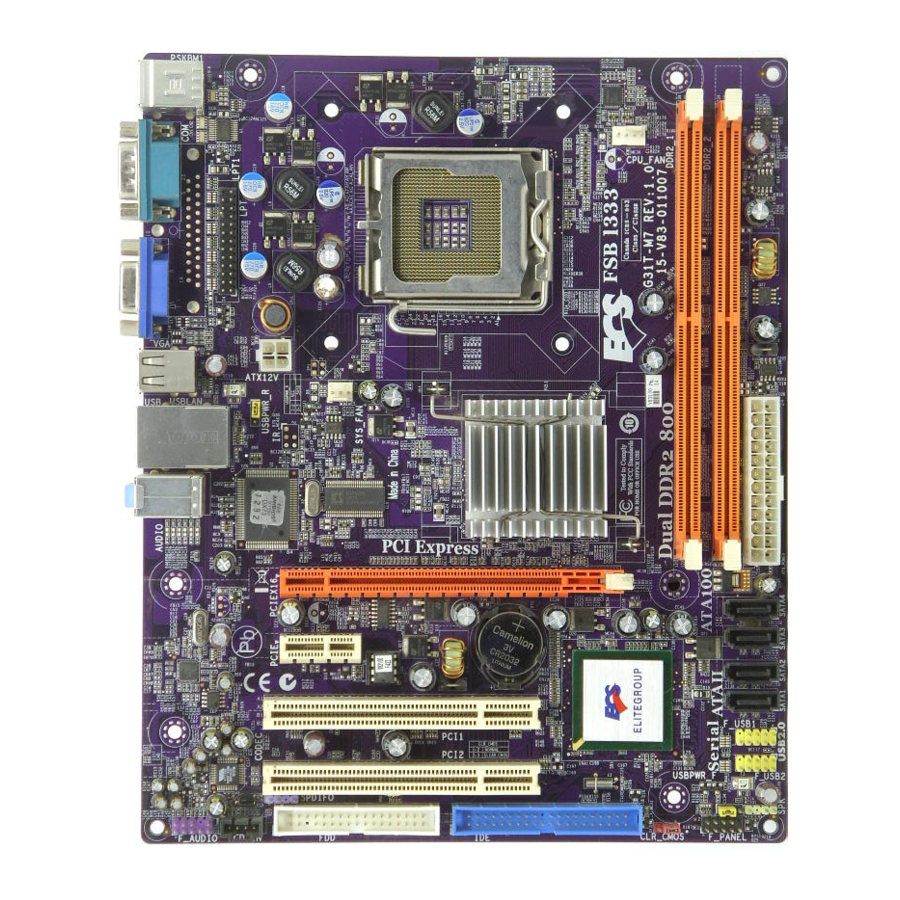
Motherboard Components Introducing the Motherboard... -
Page 11: Table Of Motherboard Components
Table of Motherboard Components LABEL COMPONENTS ® ™ LGA775 socket for Intel Yorkfield/Wolfdale/Core ® 1. CPU Socket Quad (Q6600/Q6700 G0)/Pentium Dual-Core/ ® Celeron 4xx Series processors 2. CPU_FAN CPU cooling fan connector 3. DDR2_1~2 240-pin DDR2 SDRAM slots 4. ATX_POWER Standard 24-pin ATX power connector 5. - Page 12 Memo Introducing the Motherboard...
-
Page 13: Installing The Motherboard
Chapter 2 Installing the Motherboard Safety Precautions • Follow these safety precautions when installing the motherboard • Wear a grounding strap attached to a grounded device to avoid dam- age from static electricity • Discharge static electricity by touching the metal case of a safely grounded object before working on the motherboard •... -
Page 14: Checking Jumper Settings
Do not over-tighten the screws as this can stress the motherboard. Checking Jumper Settings This section explains how to set jumpers for correct configuration of the motherboard. Setting Jumpers Use the motherboard jumpers to set system configuration options. Jumpers with more than one pin are numbered. -
Page 15: Checking Jumper Settings
Checking Jumper Settings The following illustration shows the location of the motherboard jumpers. Pin 1 is labeled. Jumper Settings Jumper Type Description Setting (default) 1-2: NORMAL 2-3: CLEAR CMOS CLR_CMOS 3-pin Clear CMOS Before clearing the CLR_CMOS CMOS, make sure to turn off the system. -
Page 16: Connecting Case Components
Connecting Case Components After you have installed the motherboard into a case, you can begin connecting the motherboard components. Refer to the following: Connect the CPU cooling fan cable to CPU_FAN. Connect the system cooling fan connector to SYS_FAN. Connect the case switches and indicator LEDs to the F_PANEL. Connect the case speaker cable to SPK. -
Page 17: Atx 24-Pin Power Connector
CPU_FAN: CPU Cooling FAN Power Connector Signal Name Function System Ground Power +12V +12V Sensor Sense Users please note that the fan connector supports the CPU cooling fan of 1.1A ~ 2.2A (26.4W max) at +12V. SYS_FAN: System Cooling FAN Power Connector Signal Name Function System Ground... -
Page 18: Front Panel Header
SPK: Internal speaker Signal Name Signal Front Panel Header The front panel header (F_PANEL) provides a standard set of switch and LED headers commonly found on ATX or micro-ATX cases. Refer to the table below for information: F_PANEL Signal Function Signal Function HD_LED_P Hard disk LED (+) -
Page 19: Installing Hardware
Installing Hardware Installing the Processor Caution: When installing a CPU heatsink and cooling fan make sure that you DO NOT scratch the motherboard or any of the surface- mount resistors with the clip of the cooling fan. If the clip of the cooling fan scrapes across the motherboard, you may cause serious damage to the motherboard or its components. -
Page 20: Cpu Installation Procedure
CPU Installation Procedure The following illustration shows CPU installation components. A. Read and follow the instructions shown on the sticker on the CPU cap. B. Unload the cap · Use thumb & forefinger to hold the lifting tab of the cap. ·... -
Page 21: Installing Memory Modules
Installing Memory Modules This motherboard accommodates two memory modules. It can support two 240-pin DDR2 800/667. The total memory capacity is 4 GB. DDR2 SDRAM memory module table Memory module Memory Bus DDR2 667 333 MHz DDR2 800 400 MHz You must install at least one module in any of the two slots. - Page 22 Table A: DDR2 (memory module) QVL (Qualified Vendor List) The following DDR2 800/667 memory modules have been tested and qualified for use with this motherboard. Type Size Vendor Module Name VALUESELECT 32M8CEC Corsair 64M8CFE PS1000545 Corsair K4T51083QC GEIL GL2L64M088BA18W 512 MB Ramaxel 5LB31 D9DCL SAMSUNG...
-
Page 23: Installing A Hard Disk Drive/Cd-Rom/Sata Hard Drive
Installing a Hard Dish Drive/CD-ROM/SATA Hard Drive This section describes how to install IDE devices such as a hard disk drive and a CD- ROM drive. About IDE Devices Your motherboard has one IDE channel interface. An IDE ribbon cable supporting two IDE devices is bundled with the motherboard. -
Page 24: Installing A Floppy Diskette Drive
Refer to the illustration below for proper installation: Attach either cable end to the connector on the motherboard. Attach the other cable end to the SATA hard drive. Attach the SATA power cable to the SATA hard drive and connect the other end to the power supply. -
Page 25: Installing Add-On Cards
Installing Add-on Cards The slots on this motherboard are designed to hold expansion cards and connect them to the system bus. Expansion slots are a means of adding or enhancing the motherboard’s features and capabilities. With these efficient facilities, you can in- crease the motherboard’s capabilities by adding hardware that performs tasks that are not part of the basic system. - Page 26 Follow these instructions to install an add-on card: Remove a blanking plate from the system case corresponding to the slot you are going to use. Install the edge connector of the add-on card into the expansion slot. Ensure that the edge connector is correctly seated in the slot. Secure the metal bracket of the card to the system case with a screw.
-
Page 27: Connecting Optional Devices
Connecting Optional Devices Refer to the following for information on connecting the motherboard’s optional devices: F_AUDIO: Front Panel Audio header for Azalia This header allows the user to install auxiliary front-oriented microphone and line- out ports for easier access. Signal Name Signal Name PORT 1L AUD_GND... - Page 28 F_USB1~2: Front Panel USB headers The motherboard has four USB ports installed on the rear edge I/O port array. Additionally, some computer cases have USB ports at the front of the case. If you have this kind of case, use auxiliary USB connector to connect the front-mounted ports to the motherboard.
- Page 29 LPT: Onboard parallel port header Signal Name Signal Name STROBE ERROR INIT SLCTIN Ground Ground Ground Ground Ground Ground BUSK Ground Ground SLCT Installing the Motherboard...
-
Page 30: Connecting I/O Devices
Connecting I/O Devices The backplane of the motherboard has the following I/O ports: PS2 Mouse Use the upper PS/2 port to connect a PS/2 pointing device. PS2 Keyboard Use the lower PS/2 port to connect a PS/2 keyboard. Serial Port Use the COM port to connect serial devices such as mice or (COM) fax/modems. -
Page 31: Using Bios
Chapter 3 Using BIOS About the Setup Utility The computer uses the latest “American Megatrends Inc. ” BIOS with support for Windows Plug and Play. The CMOS chip on the motherboard contains the ROM setup instructions for configuring the motherboard BIOS. The BIOS (Basic Input and Output System) Setup Utility displays the system’s configuration status and provides you with options to set system parameters. -
Page 32: Bios Navigation Keys
Press DEL to enter SETUP Press the delete key to access the BIOS Setup Utility. CMOS Setup Utility -- Copyright (C) 1985-2005, American Megatrends, Inc. Standard CMOS Setup Frequency/Voltage Control Advanced Setup Load Default Settings Advanced Chipset Setup Supervisor Password Integrated Peripherals User Password Power Management Setup... -
Page 33: Updating The Bios
Updating the BIOS You can download and install updated BIOS for this motherboard from the manufacturer’s Web site. New BIOS provides support for new peripherals, improve- ments in performance, or fixes for known bugs. Install new BIOS as follows: If your motherboard has a BIOS protection jumper, change the setting to allow BIOS flashing. -
Page 34: Standard Cmos Setup
Standard CMOS Setup This option displays basic information about your system. CMOS Setup Utility -- Copyright (C) 1985-2005, American Megatrends, Inc. Standard CMOS Setup Date Thu 05/29/2008 Help Item Time 18 : 47 : 06 User [Enter], [TAB] Primary IDE Master Hard Disk or [SHIFT-TAB] to Primary IDE Slave... - Page 35 Type (Auto) Use this item to configure the type of the IDE device that you specify. If the feature is enabled, it will enhance hard disk performance by reading or writing more data during each transfer. LBA/Large Mode (Auto) Use this item to set the LAB/Large mode to enhance hard disk performance by optimizing the area the hard disk is visited each time.
-
Page 36: Advanced Setup
Advanced Setup This page sets up more advanced information about your system. Handle this page with caution. Any changes can affect the operation of your computer. CMOS Setup Utility - Copyright (C) 1985-2005, American Megatrends, Inc. Advanced Setup Thermal Management Enabled Help Item TM Status... - Page 37 APIC Mode (Enabled) This item allows you to enable or disable the APCI (Advanced Programmable Inter- rupt Controller) mode. APIC provides symmetric multi-processing (SMP) for sys- tems, allowing support for up to 60 processors. 1st/2nd/3rd Boot Device (ST3320620AS/BENQ DVD DC DW1810/1st FLOPPY DRIVE) Use this item to determine the device order the computer used to look for an operating system to load at start-up time.
- Page 38 CD/DVD Drives (Press Enter) Scroll to this item and press <Enter> to view the following screen: CMOS Setup Utility - Copyright (C) 1985-2005, American Megatrends, Inc. CD/DVD Drives CD/DVD Drives Help Item 1st Drive BENQ DVD DC DW1810 Specifies the boot sequence from the available devices.
-
Page 39: Advanced Chipset Setup
Advanced Chipset Setup This page sets up more advanced information about your system. Handle this page with caution. Any changes can affect the operation of your computer. CMOS Setup Utility - Copyright (C) 1985-2005, American Megatrends, Inc. Advanced Chipset Setup DRAM Frequency Auto Help Item... -
Page 40: Integrated Peripherals
Integrated Peripherals This page sets up some parameters for peripheral devices connected to the system. CMOS Setup Utility - Copyright (C) 1985-2005, American Megatrends, Inc. Integrated Peripherals Onboard IDE Controller Enabled Help Item OnBoard SATA Controller Enhanced Onboard LAN Function Enabled DISABLED: disables the in- Onboard LAN Boot ROM... -
Page 41: Power Management Setup
Parallel Port IRQ (IRQ7) Use this item to assign IRQ to the parallel port. USB Functions (Enabled) Use this item to enable or disable the USB function. Legacy USB Support (Enabled) Use this item to enable or disable support for legacy USB devices. Setting to Auto allows the system to detect the presence of USB device at startup. - Page 42 Soft-Off by PWR-BTTN (Delay 4 Sec) Under ACPI (Advanced Configuration and Power management Interface) you can create a software power down. In a software power down, the system can be resumed by Wake Up Alarms. This item lets you install a software power down that is con- trolled by the power button on your system.
-
Page 43: Pci/Pnp Setup
PCI / PnP Setup This page sets up some parameters for devices installed on the PCI bus and those utilizing the system plug and play capability. CMOS Setup Utility - Copyright (C) 1985-2005, American Megatrends, Inc. PCI / PnP Setup Help Item Init Display First Allocate IRQ to PCI VGA... - Page 44 This item allows you to enable/disable the control of the system fan speed by chang- ing the fan voltage. ECS supports the latest PECI host technology. While using Wolfdale or Yorkfield CPU, the original images of the BIOS item “PC Health Status”...
- Page 45 CMOS Setup Utility - Copyright (C) 1985-2005, American Megatrends, Inc. Smart Fan Function Help Item SMART Fan Control Enabled SMART Fan start PWM value Options SMART Fan start Offset (-) CPU DeltaT Disabled Fan1 Slope PWM value/1 Unit Enabled Fan1 Full Speed Offset (-) SMART Fan2 Control Disabled : Move...
-
Page 46: Frequency/Voltage Control
Frequency/Voltage Control This page enables you to set the clock speed and system bus for your system. The clock speed and system bus are determined by the kind of processor you have in- stalled in your system. CMOS Setup Utility - Copyright (C) 1985-2005, American Megatrends, Inc. Frequency/Voltage Control Help item Manufacturer : Intel... -
Page 47: Load Default Settings
Load Default Settings This option opens a dialog box that lets you install stability-oriented defaults for all appropriate items in the Setup Utility. Select <OK> and then press <Enter> to install the defaults. Select <Cancel> and then press <Enter> to not install the defaults. -
Page 48: User Password
User Password This page helps you install or change a password. CMOS Setup Utility - Copyright (C) 1985-2005, American Megatrends, Inc. User Password User Password : Not Installed Help item : Move Enter : Select +/-/: Value F10: Save ESC: Exit F1:General Help F9: Load Default Settings User Password (Not Installed) -
Page 49: Using The Motherboard Software
Chapter 4 Using the Motherboard Software About the Software CD-ROM The support software CD-ROM that is included in the motherboard package contains all the drivers and utility programs needed to properly run the bundled products. Below you can find a brief description of each software program, and the location for your motherboard version. -
Page 50: Running Setup
Setup Tab Setup Click the Setup button to run the software installation program. Select from the menu which software you want to install. Browse CD The Browse CD button is the standard Windows command that al- lows you to open Windows Explorer and show the contents of the support CD. - Page 51 Click Next. The following screen appears: Check the box next to the items you want to install. The default options are recom- mended. Click Next run the Installation Wizard. An item installation screen appears: Follow the instructions on the screen to install the items. 1.
- Page 52 Method 1. Run Reboot Setup Windows Vista will block startup programs by default when installing drivers after the system restart. You must select taskbar icon Run Blocked Program and run Reboot Setup to install the next driver, until you finish all drivers installation. Method 2.
- Page 53 Select Classic View. Set User Account. Select Turn User Account Control on or off and press Continue. Using the Motherboard Software...
-
Page 54: Manual Installation
Disable User Account Control (UAC) to help protect your computer item and press OK, then press Restart Now. Then you can restart your computer and continue to install drivers without running blocked programs. Manual Installation Insert the CD in the CD-ROM drive and locate the PATH.DOC file in the root directory.
Need help?
Do you have a question about the G31T-M7 and is the answer not in the manual?
Questions and answers