Table of Contents
Advertisement
Advertisement
Table of Contents

Related Manuals for Supermicro X10SDV-TLN4F


Summary of Contents for Supermicro X10SDV-TLN4F
- Page 1 X10SDV-TLN4F X10SDV-F USER’S MANUAL...
- Page 2 This product, including software and docu- mentation, is the property of Supermicro and/or its licensors, and is supplied only under a license. Any use or reproduction of this product is not allowed, except as expressly permitted by the terms of said license.
-
Page 3: About This Motherboard
Xeon ® D-1540 SoC (System-on-a-Chip) processor in a BGA package. The X10SDV-TLN4F/F Mini-ITX motherboards address a low-power, high-density infrastructure need with 8 Xeon cores and 128 GB of addressable memory, two integrated 10 Gigabit Intel Ethernet ports (-TLN4F only), M.2 SSD, USB 3.0 and a thermal design up to 45 watts only. -
Page 4: Conventions Used In The Manual
X10SDV-TLN4F/F Motherboard User’s Manual Conventions Used in the Manual: Special attention should be given to the following symbols for proper installation and to prevent damage done to the components or injury to yourself: Warning: Critical information to prevent damage to the components or injury to your- self. -
Page 5: Contacting Supermicro
Super Micro Computer, Inc. 980 Rock Ave. San Jose, CA 95131 U.S.A. Tel: +1 (408) 503-8000 Fax: +1 (408) 503-8008 Email: marketing@supermicro.com (General Information) support@supermicro.com (Technical Support) Web Site: www.supermicro.com Europe Address: Super Micro Computer B.V. Het Sterrenbeeld 28, 5215 ML... -
Page 6: Table Of Contents
X10SDV-TLN4F/F Motherboard User’s Manual Table of Contents Preface About This Motherboard ....................iii Manual Organization ..................... iii Conventions Used in the Manual: .................iv Contacting Supermicro ....................v Chapter 1 Introduction Overview ......................1-1 Checklist ......................1-1 Motherboard Features ..................1-8 Processor Overview ..................1-11 Special Features ................... - Page 7 Table of Contents Universal Serial Bus (USB) ..............2-12 Unit Identifier Switch ................2-13 VGA ......................2-13 Front Control Panel ..................2-14 Front Control Panel Pin Definitions............... 2-15 Power LED ....................2-15 HDD LED ....................2-16 NIC1/NIC2 (LAN1/LAN2) ................2-16 Overheat (OH)/Fan Fail/PWR Fail/UID LED ..........
- Page 8 X10SDV-TLN4F/F Motherboard User’s Manual GbE LAN LEDs ..................2-32 BMC Heartbeat LED ................2-32 Onboard Power LED ................2-33 Overheat/PWR Fail/Fan Fail LED ............2-33 Unit Identification LED ................2-34 SATA Connections ..................2-35 SATA Ports (I-SATA0 ~ I-SATA5) ............2-35 M.2 Socket ....................
-
Page 9: Chapter 1 Introduction
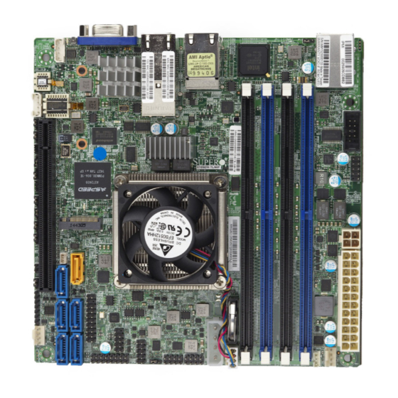
Checklist Congratulations on purchasing your computer motherboard from an acknowledged leader in the industry. Supermicro boards are designed with the utmost attention to detail to provide you with the highest standards in quality and performance. Please check that the following items have all been included with your motherboard. - Page 10 X10SDV-TLN4F/F Motherboard User’s Manual X10SDV-TLN4F Motherboard Image Note: All graphics shown in this manual were based upon the latest PCB Revision available at the time of publishing of the manual. The motherboard you have re- ceived may or may not look exactly the same as the graphics shown in this manual.
- Page 11 Chapter 1: Introduction X10SDV-F Motherboard Image...
- Page 12 X10SDV-TLN4F/F Motherboard User’s Manual X10SDV-TLN4F/F Motherboard Layout JPL1 VGA1 i350 JNVI2C1 SRW2 LAN1/2 LAN3/4 LED8 X10SDV-TLN4F SRW1 REV:1.01 DESIGNED IN USA AST2400 SLOT7 PCI-E3.0 X16 LEDM1 I-SATA1 I-SATA2 JBT1 USB 4/5 LED3 JGPIO1 I-SATA4 I-SGPIO2 I-SGPIO1 JPME1 FAN2 Important Notes to the User 1.
- Page 13 Chapter 1: Introduction X10SDV-TLN4F/F Motherboard Quick Reference LAN3/4 USB0/1 LED7 VGA1 LAN1/2 JPL1 IPMI LAN JNVI2C1 JPL1 VGA1 i350 JNVI2C1 SRW2 JIPMB1 SRW2 LAN1/2 LED8 JPG1 LAN3/4 SRW1 LED8 COM1 JPB1 JOH1 X10SDV-TLN4F SRW1 REV:1.01 JI2C1 DESIGNED IN USA USB2/3...
- Page 14 X10SDV-TLN4F/F Motherboard User’s Manual Jumpers Jumper Description Default JBR1 BIOS Recovery Pins 1-2 (Normal) JBT1 CMOS Clear Open: Normal, Short: Clear CMOS C1/JI SMB to PCI-Exp. Slots Pins 2-3 (Disabled) JPG1 VGA Enable Pins 1-2 (Enabled) JPL1 LAN1/LAN2 Enable Pins 1-2 (Enabled)
- Page 15 Chapter 1: Introduction LAN1~LAN2 Gigabit Ethernet (RJ45) Ports LAN3~LAN4 10G Ethernet (RJ45) Ports (TLN4F Only) 4-pin 12V DC Power Connector (To provide alternative power for special enclosure when the 24-pin ATX power is not in use.) SLOT7 PCI-E 3.0 x16 Slot SRW1, SRW2 M.2 Holding Screws USB 0/1...
-
Page 16: Motherboard Features
X10SDV-TLN4F/F Motherboard User’s Manual Motherboard Features Intel ® Xeon ® D-1540 SoC Processor (BGA) onboard 12MB Cache, 8 Cores, 16 Threads, 2.0 - 2.6GHz Memory Supports up to 128GB DDR4 ECC RDIMM or 64GB DDR4 ECC/Non-ECC UDIMM with speeds of 1600MHz,... - Page 17 Chapter 1: Introduction Plug and Play, ACPI 5.0, SMBIOS 2.8, BIOS Rescue Hot-Key, RTC Wakeup, Dual-Boot Block Power Configuration ACPI/ACPM Power Management (S0, S4 and S5 only) Wake-On LAN Power Button Override Power-on mode for AC power recovery PC Health Monitoring Onboard Voltage Monitoring +1.8V, +3.3V, +5V, +/-12V, +3.3V Stby, +5V Stby, VBAT, HT, Memory, PCH Temp, System Temp, Memory Temp...
-
Page 18: System Block Diagram
X10SDV-TLN4F/F Motherboard User’s Manual X10SDV-TLN4F/F Block Diagram JPCIE1 PCI-E 3.0 PCIE 3.0 x16 PCIE 3.0 x16 M.2 connector PCIE 3.0 x3 PCIE 3.0 x4 PCI-E 3.0 or SATA 3.0 x1 PCIE 3.0 x1 SWITCH PCI-E 3.0 TLN4F only SWITCH LAN KR... -
Page 19: Processor Overview
Chapter 1: Introduction Processor Overview The Intel ® Xeon ® D-1500 product family is the third generation, low-powered 64-bit SoC (System-on-a-Chip) processor that is optimized to deliver high performance, energy effiency and enhanced total cost of ownership solutions. The low-power consumption of the processor makes it suitable for dense servers that can ef- fectively take on hyperscale workloads, intelligent edge network or ultra-dense embedded devices. -
Page 20: Special Features
Environmental Temperature Control The X10SDV-F motherboard comes with a passive heatsink built in, while the X10SDV-TLN4F comes with an active heatsink. Please follow the instructions given in your system design guide or your system user manual to provide adequate airflow to your system. -
Page 21: Acpi Features
Chapter 1: Introduction ACPI Features ACPI stands for Advanced Configuration and Power Interface. The ACPI specifica- tion defines a flexible and abstract hardware interface that provides a standard way to integrate power management features throughout a PC system, including its hardware, operating system and application software. This enables the system to automatically turn on and off peripherals such as CD-ROMs, network cards, hard disk drives and printers. - Page 22 X10SDV-TLN4F/F Motherboard User’s Manual Notes 1-14...
-
Page 23: Chapter 2 Installation
The following statements are industry-standard warnings, provided to warn the user of situations which have the potential for bodily injury. Should you have questions or experience difficulty, contact Supermicro's Technical Support department for assis- tance. Only certified technicians should attempt to install or configure components. - Page 24 X10SDV-TLN4F/F Motherboard User’s Manual Attention Danger d'explosion si la pile n'est pas remplacée correctement. Ne la remplacer que par une pile de type semblable ou équivalent, recommandée par le fabricant. Jeter les piles usagées conformément aux instructions du fabricant. ¡Advertencia! Existe peligro de explosión si la batería se reemplaza de manera incorrecta.
-
Page 25: Product Disposal
Chapter 2: Installation Product Disposal Warning! Ultimate disposal of this product should be handled according to all national laws and regulations. 製品の廃棄 この製品を廃棄処分する場合、 国の関係する全ての法律 ・ 条例に従い処理する必要が あり ます。 警告 本产品的废弃处理应根据所有国家的法律和规章进行。 警告 本產品的廢棄處理應根據所有國家的法律和規章進行。 Warnung Die Entsorgung dieses Produkts sollte gemäß allen Bestimmungen und Gesetzen des Landes erfolgen. -
Page 26: Static-Sensitive Devices
X10SDV-TLN4F/F Motherboard User’s Manual القىانين واللىائح الىطنية جميع وفقا ل ينبغي التعامل معه هذا المنتج من التخلص النهائي عند 경고! 이 제품은 해당 국가의 관련 법규 및 규정에 따라 폐기되어야 합니다. Waarschuwing De uiteindelijke verwijdering van dit product dient te geschieden in overeenstemming met alle nationale wetten en reglementen. -
Page 27: Motherboard Installation
Philips Screwdriver Standoffs (4) Philips Screws (4) Only if Needed Location of Mounting Holes JPL1 VGA1 i350 JNVI2C1 SRW2 LAN1/2 LAN3/4 LED8 X10SDV-TLN4F SRW1 REV:1.01 DESIGNED IN USA AST2400 SLOT7 PCI-E3.0 X16 LEDM1 I-SATA1 I-SATA2 JBT1 USB 4/5 LED3 JGPIO1... -
Page 28: Installing The Motherboard
X10SDV-TLN4F/F Motherboard User’s Manual Installing the Motherboard 1. Install the I/O shield into the back of the chassis. 2. Locate the mounting holes on the motherboard. (See the previous page.) 3. Locate the matching mounting holes on the chassis. Align the mounting holes on the motherboard against the mounting holes on the chassis. -
Page 29: Memory Support
Chapter 2: Installation Memory Support The X10SDV-TLN4F/F motherboard supports up to 128GB of DDR4 ECC RDIMM or 64GB of DDR4 ECC/Non-ECC UDIMM with speeds up to 2133MHz in four memory slots. Populating these DIMM slots with memory modules of the same type and size will result in interleaved memory, which will improve memory per- formance. -
Page 30: Memory Installation Guidelines
X10SDV-TLN4F/F Motherboard User’s Manual Memory Installation Guidelines When installing memory modules, the DIMM slots should be populated in the following order: DIMMA1, DIMMB1, then DIMMA2, DIMMB2. • Always use DDR4 DIMM modules of the same size, type and speed. Mixing memory modules of different types and speeds is not allowed. -
Page 31: Connectors/Io Ports
The I/O ports are color coded in conformance with the industry standards. See the figure below for the colors and locations of the various I/O ports. Back panel I/O Panel JPL1 VGA1 i350 JNVI2C1 SRW2 LAN1/2 LAN3/4 LED8 X10SDV-TLN4F SRW1 REV:1.01 DESIGNED IN USA AST2400 SLOT7 PCI-E3.0 X16 LEDM1 I-SATA1 I-SATA2 JBT1... -
Page 32: Serial Port
X10SDV-TLN4F/F Motherboard User’s Manual Serial Port COM Port 1 Pin Definitions COM1 port is located near DIMM slot Pin # Definition Pin # Definition A1 to provide a front accessible serial connection. See the table on the right for pin definitions. -
Page 33: Ethernet Ports
TD3- Ground A. LAN1 B. LAN2 C. LAN3 D. LAN4 E. IPMI LAN JPL1 VGA1 i350 JNVI2C1 SRW2 LAN1/2 LAN3/4 LED8 X10SDV-TLN4F SRW1 REV:1.01 DESIGNED IN USA AST2400 SLOT7 PCI-E3.0 X16 LEDM1 I-SATA1 I-SATA2 JBT1 USB 4/5 LED3 JGPIO1 I-SATA4... -
Page 34: Universal Serial Bus (Usb)
X10SDV-TLN4F/F Motherboard User’s Manual Universal Serial Bus (USB) Two USB 3.0 ports (USB0/1) are located on the I/O back plane. Two USB 2.0 headers (USB2/3, 4/5) are on the motherboard to provide front panel access. USB cables are not included. See the tables below for pin definitions. -
Page 35: Unit Identifier Switch
Note: UID can also be triggered via IPMI on the motherboard. For more information on IPMI, please refer to the IPMI User's Guide posted on our website at http://www.supermicro. com. A. UID Switch A VGA port is located next to the LAN ports on B. -
Page 36: Front Control Panel
These connectors are designed spe- cifically for use with Supermicro chassis. See the figure below for the descriptions of the front control panel buttons and LED indicators. Refer to the following section for descriptions and pin definitions. -
Page 37: Front Control Panel Pin Definitions
Chapter 2: Installation Front Control Panel Pin Definitions Power LED Power LED Pin Definitions (JF1) The Power LED connection is located Pin# Definition on pins 15 and 16 of JF1. Refer to the 3.3V table on the right for pin definitions. PWR LED A. -
Page 38: Hdd Led
X10SDV-TLN4F/F Motherboard User’s Manual HDD LED HDD LED Pin Definitions (JF1) The HDD LED connection is located Pin# Definition on pins 13 and 14 of JF1. Attach a 3.3V Standby cable here to indicate the status of HD LED HDD-related activities, including IDE, SATA activities. -
Page 39: Overheat (Oh)/Fan Fail/Pwr Fail/Uid Led
Chapter 2: Installation Overheat (OH)/Fan Fail/PWR Fail/ OH/Fan Fail/ PWR Fail/Blue_UID LED UID LED Pin Definitions (JF1) Pin# Definition Connect an LED cable to pins 7 and Blue_UID LED 8 of Front Control Panel to use the OH/Fan Fail/Power Fail Cathode Overheat/Fan Fail/Power Fail and UID LED connections. -
Page 40: Reset Button
X10SDV-TLN4F/F Motherboard User’s Manual Reset Button Reset Button Pin Definitions (JF1) The Reset Button connection is located Pin# Definition on pins 3 and 4 of JF1. Attach it to a Reset hardware reset switch on the computer Ground case to reset the system. Refer to the table on the right for pin definitions. -
Page 41: Connecting Cables
Pin# Definition A. 24-Pin ATX Power B. 12V DC Power C. 4-Pin HDD Power JPL1 VGA1 i350 JNVI2C1 SRW2 LAN1/2 LAN3/4 LED8 X10SDV-TLN4F SRW1 REV:1.01 DESIGNED IN USA AST2400 SLOT7 PCI-E3.0 X16 LEDM1 I-SATA1 I-SATA2 JBT1 USB 4/5 LED3 JGPIO1... -
Page 42: Fan Headers (Fan1 ~ Fan3)
X10SDV-TLN4F/F Motherboard User’s Manual Fan Headers (FAN1 ~ FAN3) Fan Header Pin Definitions This motherboard has three fan headers. These Pin# Definition fans are 4-pin headers. Although pins 1-3 of the Ground (Black) fan headers are backward compatible with the... -
Page 43: System Management Bus Header
See the table on the right for pin Ground definitions. A. NVMe Header B. DOM Power JPL1 VGA1 i350 JNVI2C1 SRW2 LAN1/2 LAN3/4 LED8 X10SDV-TLN4F SRW1 REV:1.01 DESIGNED IN USA AST2400 SLOT7 PCI-E3.0 X16 LEDM1 I-SATA1 I-SATA2 JBT1 USB 4/5 LED3... -
Page 44: Tpm Header/Port 80 Header
X10SDV-TLN4F/F Motherboard User’s Manual TPM Header/Port 80 Header TPM/Port 80 Header Pin Definitions A Trusted Platform Module/Port 80 Pin # Definition Pin # Definition header, located at JTPM1, provides LCLK Trusted-Platform (TPM) support and LFRAME# <(KEY)> Port 80 connection. Use this header... -
Page 45: Speaker
Ground tions. No connection A. JD1 B. Standby Power JPL1 VGA1 i350 JNVI2C1 SRW2 LAN1/2 LAN3/4 LED8 X10SDV-TLN4F SRW1 REV:1.01 DESIGNED IN USA AST2400 SLOT7 PCI-E3.0 X16 LEDM1 I-SATA1 I-SATA2 JBT1 USB 4/5 LED3 JGPIO1... -
Page 46: I-Sgpio1/I-Sgpio2
X10SDV-TLN4F/F Motherboard User’s Manual I-SGPIO1/I-SGPIO2 Serial Link General Purpose Headers (SGPIO) Two Serial Link General Purpose In- Pin Definitions put/Output (SGPIO) headers are used Pin# Definition Definition to communicate with the enclosure management chip in the system. See Ground DATA Out... -
Page 47: Nvme I2C Header
Chapter 2: Installation NVMe I2C Header Connector JNVI2C is a management header for the Supermicro AOC NVMe PCI-E peripheral cards. Please connect the I2C cable to this connector. A. PCI-E NVMe I2C Header JPL1 VGA1 i350 JNVI2C1 SRW2 LAN1/2 LAN3/4... -
Page 48: Jumper Settings
X10SDV-TLN4F/F Motherboard User’s Manual Jumper Settings Explanation of Jumpers To modify the operation of the mother- board, jumpers can be used to choose between optional settings. Jumpers create shorts between two pins to change the function of the connector. Pin 1 is identified with a square solder pad on the printed circuit board. -
Page 49: Cmos Clear
PCI-E slot. See the table on the right for jumper settings. A. Clear CMOS B. JI C. JI JPL1 VGA1 i350 JNVI2C1 SRW2 LAN1/2 LAN3/4 LED8 X10SDV-TLN4F SRW1 REV:1.01 DESIGNED IN USA AST2400 SLOT7 PCI-E3.0 X16 LEDM1 I-SATA1 I-SATA2 JBT1 USB 4/5 LED3... -
Page 50: Watch Dog Timer Enable
X10SDV-TLN4F/F Motherboard User’s Manual Watch Dog Timer Enable Watch Dog Jumper Settings Watch Dog (JWD1) is a system monitor that Pin# Definition can be used to enter LAN bypass default set- Reset (Default) tings, reset the system or enter NMI when the Timer expires. -
Page 51: Management Engine (Me) Recovery
See the table on the right for jumper settings. A. ME Recovery B. Manufacturing Mode JPL1 VGA1 i350 JNVI2C1 SRW2 LAN1/2 LAN3/4 LED8 X10SDV-TLN4F SRW1 REV:1.01 DESIGNED IN USA AST2400 SLOT7 PCI-E3.0 X16 LEDM1 I-SATA1 I-SATA2 JBT1 USB 4/5... -
Page 52: Bios Recovery
X10SDV-TLN4F/F Motherboard User’s Manual BIOS Recovery BIOS Recovery Jumper Settings Close pins 2 and 3 of jumper JBR1 for Pin# Definition BIOS recovery. The default setting is on Normal pins 1 and 2 for normal operation. See BIOS Recovery the table on the right for jumper settings. -
Page 53: Usb Wake-Up
Enabled (Default) right for jumper settings. Disabled A. USB Wake-up B. 10Gb Ethernet Support JPL1 VGA1 i350 JNVI2C1 SRW2 LAN1/2 LAN3/4 LED8 X10SDV-TLN4F SRW1 REV:1.01 DESIGNED IN USA AST2400 SLOT7 PCI-E3.0 X16 LEDM1 I-SATA1 I-SATA2 JBT1 USB 4/5 LED3 JGPIO1... -
Page 54: Onboard Indicators
X10SDV-TLN4F/F Motherboard User’s Manual Onboard Indicators Activity LED GbE LAN LEDs There are four GbE LAN ports on the Color Status Definition motherboard. Each Gigabit Ethernet LAN No Connections port has two LEDs. The Yellow LED in- Yellow Flashing Active dicates connection and activity. -
Page 55: Onboard Power Led
Blinking PWR Fail or Fan Fail A. PWR LED B. OH/PWR Fail/Fan Fail LED JPL1 VGA1 i350 JNVI2C1 SRW2 LAN1/2 LAN3/4 LED8 X10SDV-TLN4F SRW1 REV:1.01 DESIGNED IN USA AST2400 SLOT7 PCI-E3.0 X16 LEDM1 I-SATA1 I-SATA2 JBT1 USB 4/5 LED3... -
Page 56: Unit Identification Led
X10SDV-TLN4F/F Motherboard User’s Manual Unit Identification LED UID LED Status A rear UID LED indicator (LED7) is located Color/State Status next to the Unit Identifier (UID) switch on the Blue: On Unit Identified I/O back panel. The front panel UID LED is located at Pin 7 of the Front Control Panel at JF1. -
Page 57: Sata Connections
There are six SATA 3.0 ports on the motherboard. These ports provide serial-link signal connections, which are faster than the connections of Parallel ATA. I-SATA0 also supports SuperDOM, Supermicro proprietary SATA DOM with built-in power connection via pin 8. M.2 Socket M.2 is formerly known as Next Generation Form Factor (NGFF). - Page 58 X10SDV-TLN4F/F Motherboard User’s Manual Notes 2-36...
-
Page 59: Chapter 3 Troubleshooting
Chapter 3: Troubleshooting Chapter 3 Troubleshooting Troubleshooting Procedures Use the following procedures to troubleshoot your system. If you have followed all of the procedures below and still need assistance, refer to the ‘Technical Support Procedures’ and/or ‘Returning Merchandise for Service’ section(s) in this chapter. Always disconnect the AC power cord before adding, changing or installing any hardware components. -
Page 60: Memory Errors
2. You should be using ECC or Non-ECC DDR4 UDIMM (1.5V, 1.35V) 1600/1333 MHz memory recommended by Supermicro. Also, it is required that you use the memory modules of the same type and speed for all DIMMs in the system. Do not use memory modules of different sizes, different speeds, nor different types on the same motherboard. -
Page 61: Technical Support Procedures
Before contacting Technical Support, please make sure that you have followed all the steps listed below. Also, Note that as a motherboard manufacturer, Supermicro does not sell directly to end users, so it is best to first check with your distributor or reseller for troubleshooting services. -
Page 62: Frequently Asked Questions
Frequently Asked Questions Question: What type of memory does my motherboard support? Answer: The X10SDV-TLN4F/F motherboard supports up to 128GB of DDR4 ECC RDIMM or 64GB of DDR4 ECC/Non-ECC UDIMM memory of speeds up to 2133MHz. See Section 2-4 for details on installing memory. -
Page 63: Battery Removal And Installation
Chapter 3: Troubleshooting Battery Removal and Installation Battery Removal To remove the onboard battery, follow the steps below: 1. Power off your system and unplug your power cable. 2. Locate the onboard battery as shown below. 3. Using a tool such as a pen or a small screwdriver, push the battery lock out- wards to unlock it. -
Page 64: Returning Merchandise For Service
You can obtain service by calling your vendor for a Returned Merchandise Authorization (RMA) number. For faster service, you may also obtain RMA authorizations online (http://www.supermicro. com/RmaForm/). When you return the motherboard to the manufacturer, the RMA number should be prominently displayed on the outside of the shipping carton, and mailed prepaid or hand-carried. -
Page 65: Chapter 4 Bios
When an option is selected in the left frame, it is highlighted in white. Often a text message will accompany it. (Note: the AMI BIOS has default text messages built in. Supermicro retains the option to include, omit, or change any of these text messages.) The AMI BIOS setup utility uses a key-based navigation system called "hot keys". -
Page 66: How To Start The Setup Utility
Flashing the wrong BIOS can cause irreparable damage to the system. In no event shall Supermicro be liable for direct, indirect, special, incidental, or consequential dam- ages arising from a BIOS update. If you have to update the BIOS, do not shut down or reset the system while the BIOS is updating. - Page 67 Day MM/DD/YY format. The time is entered in HH:MM:SS format. Note: The time is in the 24-hour format. For example, 5:30 P.M. appears as 17:30:00. The following BIOS items will also be displayed: Supermicro X10SDV-F Version Build Date Memory Information Total Memory This displays the total size of memory available in the system.
-
Page 68: Advanced Setup Configurations
X10SDV-TLN4F/F Motherboard User’s Manual Advanced Setup Configurations Use the arrow keys to select Boot Setup and press <Enter> to access the submenu items. Warning: Take caution when changing the Advanced settings. An incorrect value, a very high DRAM frequency, or an incorrect DRAM timing setting may make the system unstable. -
Page 69: Power Configuration
Chapter 4: AMI BIOS Wait For 'F1' If Error Use this feature to force the system to wait until the 'F1' key is pressed if an error occurs. The options are Disabled and Enabled. INT19 (Interrupt 19) Trap Response Interrupt 19 is the software interrupt that handles the boot disk function. When this item is set to Immediate, the ROM BIOS of the host adaptors will "capture"... -
Page 70: Cpu Configuration
X10SDV-TLN4F/F Motherboard User’s Manual CPU Configuration The following CPU information will be displayed: • Processor ID • Processor Frequency • Processor Max Ratio • Processor Min Ratio • Microcode Revision • L1 Cache RAM • L2 Cache RAM •... - Page 71 Chapter 4: AMI BIOS Execute Disable Bit (Available if supported by the OS & the CPU) Select Enabled to enable the Execute-Disable Bit which will allow the processor to designate areas in the system memory where an application code can execute and where it cannot, thus preventing a worm or a virus from flooding illegal codes to overwhelm the processor or damage the system during an attack.
-
Page 72: Advanced Power Management Configuration
X10SDV-TLN4F/F Motherboard User’s Manual Intel ® Virtualization Technology (Available when supported by the CPU) Select Enabled to support Intel ® Virtualization Technology, which will allow one platform to run multiple operating systems and applications in independent parti- tions, creating multiple "virtual" systems in one physical computer. The options are Enable and Disable. - Page 73 Chapter 4: AMI BIOS Boot Performance Mode This feature allows the user to select the performance state that the BIOS will set before the operating system handoff. The options are Max Performance and Max Efficient. Turbo Mode Select Enable for processor cores to run faster than the frequency specified by the manufacturer.
- Page 74 X10SDV-TLN4F/F Motherboard User’s Manual Enhanced Halt State (C1E) Select Enabled to use Enhanced Halt-State technology, which will significantly reduce the CPU's power consumption by reducing the CPU's clock cycle and voltage during a Halt-state. The options are Disable and Enable.
-
Page 75: Chipset Configuration
Chapter 4: AMI BIOS SAPM Control This feature indicates whether the PCU should control the System Agent PM using its power-performance tuning algorithm. The options are Enable and Disable. Energy Efficient Turbo Use this feature to enable energy efficient turbo mode. The options are En- able and Disable. -
Page 76: Memory Configuration
X10SDV-TLN4F/F Motherboard User’s Manual ® IOAT (Intel IO Acceleration) Configuration Enable IOAT Select Enable to enable Intel I/OAT (I/O Acceleration Technology) support, which significantly reduces CPU overhead by leveraging CPU architectural improve- ments and freeing the system resource for other tasks. The options are Enable and Disable. -
Page 77: Dimm Information
Chapter 4: AMI BIOS Data Scrambling Select Enabled to enable data scrambling to enhance system performance and data integrity. The options are Auto, Disabled and Enabled. DRAM RAPL Baseline Use this feature to set the run-time power-limit baseline for DRAM modules. The options are Disable, DRAM RAPL Mode 0, and DRAM RAPL Mode 1. -
Page 78: South Bridge
X10SDV-TLN4F/F Motherboard User’s Manual Patrol Scrub Interval This feature allows you to decide how many hours the system should wait before the next complete patrol scrub is performed. Use the keyboard to enter a value from 0-24. The Default setting is 24. -
Page 79: Sata Configuration
Chapter 4: AMI BIOS EHCI1 Select Enabled to enable EHCI (Enhanced Host Controller Interface) support on USB 2.0 connector #1 (at least one USB 2.0 connector should be enabled for EHCI support). The options are Disabled and Enabled. EHCI2 Select Enabled to enable EHCI (Enhanced Host Controller Interface) support on USB 2.0 connector #2 (at least one USB 2.0 connector should be enabled for EHCI support). - Page 80 X10SDV-TLN4F/F Motherboard User’s Manual SATA Port 0~ Port 5 This item displays the information detected on the installed SATA drive on the particular SATA port. • Model number of drive and capacity • Software Preserve Support Port 0 ~ Port 5 Hot Plug This feature designates this port for hot plugging.
- Page 81 Chapter 4: AMI BIOS • ME Firmware Status #1 • ME Firmware Status #2 • Current State • Error Code PCIe/PCI/PnP Configuration The following information will display: • PCI Bus Driver Version • PCI Devices Common Settings: PCI PERR/SERR Support Select Enabled to allow a PCI device to generate a PERR/SERR number for a PCI Bus Signal Error Event.
-
Page 82: Super Io Configuration
X10SDV-TLN4F/F Motherboard User’s Manual M.2 PCI-E 3.0 X4 Use this feature to select which firmware type to be loaded for the add-on card in this slot. The options are Disabled, Legacy, and EFI. SLOT 7 PCI-E 3.0 X16 Use this feature to select which firmware type to be loaded for the add-on card in this slot. -
Page 83: Serial Port Console Redirection
Chapter 4: AMI BIOS Serial Port Select Enabled to enable the selected onboard serial port. The options are Enabled and Disabled. Device Settings This item displays the status of a serial part specified by the user. Change Port 1 Settings This feature specifies the base I/O port address and the Interrupt Request address of a serial port specified by the user. - Page 84 X10SDV-TLN4F/F Motherboard User’s Manual Data Bits Use this feature to set the data transmission size for Console Redirection. The options are 7 Bits and 8 Bits. Parity A parity bit can be sent along with regular data bits to detect data transmission errors.
- Page 85 Chapter 4: AMI BIOS Putty KeyPad This feature selects the settings for Function Keys and KeyPad used for Putty, which is a terminal emulator designed for the Windows OS. The options are VT100, LINUX, XTERMR6, SC0, ESCN, and VT400. Redirection After BIOS Post Use this feature to enable or disable legacy console redirection after BIOS POST.
- Page 86 X10SDV-TLN4F/F Motherboard User’s Manual Parity A parity bit can be sent along with regular data bits to detect data transmission errors. Select Even if the parity bit is set to 0, and the number of 1's in data bits is even. Select Odd if the parity bit is set to 0, and the number of 1's in data bits is odd.
- Page 87 Chapter 4: AMI BIOS Redirection After BIOS Post Use this feature to enable or disable legacy Console Redirection after BIOS POST. When set to Bootloader, legacy Console Redirection is disabled before booting the OS. When set to Always Enable, legacy Console Redirection remains enabled when booting the OS.
-
Page 88: Acpi Settings
X10SDV-TLN4F/F Motherboard User’s Manual Flow Control Use this item to set the flow control for Console Redirection to prevent data loss caused by buffer overflow. Send a "Stop" signal to stop sending data when the re- ceiving buffer is full. Send a "Start" signal to start sending data when the receiving buffer is empty. -
Page 89: Event Logs
Chapter 4: AMI BIOS Event Logs Use this feature to configure Event Log settings. Change SMBIOS Event Log Settings Enabling/Disabling Options SMBIOS Event Log Change this item to enable or disable all features of the SMBIOS Event Logging during system boot. The options are Enabled and Disabled. Runtime Error Logging Support Select Enabled to support Runtime Error Logging. -
Page 90: View Smbios Event Log
X10SDV-TLN4F/F Motherboard User’s Manual PCI-Ex (PCI-Express) Error Enable Select Yes for the BIOS to correct errors occurred in the PCI-E slots. The options are Yes and No. Erasing Settings Erase Event Log If No is selected, data stored in the event log will not be erased. Select Yes, Next Reset, data in the event log will be erased upon next system reboot. -
Page 91: Ipmi
Chapter 4: AMI BIOS IPMI Use this feature to configure Intelligent Platform Management Interface (IPMI) settings. BMC Firmware Revision This item indicates the IPMI firmware revision used in your system. IPMI Status (Baseboard Management Controller) This item indicates the status of the IPMI firmware installed in your system. System Event Log ... -
Page 92: Bmc Network Configuration
X10SDV-TLN4F/F Motherboard User’s Manual When SEL is Full This feature allows the user to decide what the BIOS should do when the system event log is full. Select Erase Immediately to erase all events in the log when the system event log is full. The options are Do Nothing and Erase Immediately. - Page 93 Chapter 4: AMI BIOS Station MAC Address This item displays the Station MAC address for this computer. Mac addresses are 6 two-digit hexadecimal numbers. Gateway IP Address This item displays the Gateway IP address for this computer. This should be in decimal and in dotted quad form (i.e., 172.31.0.1).
-
Page 94: Security Settings
X10SDV-TLN4F/F Motherboard User’s Manual Security Settings This menu allows the user to configure the following security settings for the system. Password Check Select Setup for the system to check for a password at Setup. Select Always for the system to check for a password at bootup or upon entering the BIOS Setup utility. - Page 95 Chapter 4: AMI BIOS Secure Boot Use this item to enable secure boot. The options are Disabled and Enabled. Secure Boot Mode Use this item to select the secure boot mode. The options are Standard and Custom. Key Management This submenu allows the user to configure the following Key Management settings.
- Page 96 X10SDV-TLN4F/F Motherboard User’s Manual Authorized Signatures Set New Key Select Yes to load the database from the manufacturer's defaults. Select No to load the DB from a file. The options are Yes and No. Append Key Select Yes to add the database from the manufacturer's defaults to the existing DB.
-
Page 97: Boot Settings
Chapter 4: AMI BIOS Boot Settings Use this feature to configure Boot Settings: Setup Prompt Timeout Use this item to indicate the length of time (the number of seconds) for the BIOS to wait before rebooting the system when the setup activation key is pressed. Enter the value of 65535 (0xFFFF) for the BIOS to wait indefinitely. - Page 98 X10SDV-TLN4F/F Motherboard User’s Manual • Boot Option #6 • Boot Option #7 • Boot Option #8 • Boot Option #9 • Boot Option #10 • Boot Option #11 • Boot Option #12 • Boot Option #13 • Boot Option #14 •...
-
Page 99: Save & Exit
Chapter 4: AMI BIOS Save & Exit Select the Exit tab from the BIOS setup utility screen to enter the Exit BIOS Setup screen. Discard Changes and Exit Select this option to quit the BIOS Setup without making any permanent changes to the system configuration, and reboot the computer. - Page 100 X10SDV-TLN4F/F Motherboard User’s Manual Restore Defaults To set this feature, select Restore Defaults from the Save & Exit menu and press <Enter>. These are factory settings designed for maximum system stability, but not for maximum performance. Save As User Defaults To set this feature, select Save as User Defaults from the Exit menu and press <En-...
-
Page 101: Appendix A Bios Error Beep Codes
Appendix A: POST Error Beep Codes Appendix A BIOS Error Beep Codes During the POST (Power-On Self-Test) routines, which are performed each time the system is powered on, errors may occur. Non-fatal errors are those which, in most cases, allow the system to continue with bootup. - Page 102 X10SDV-TLN4F/F Motherboard User’s Manual Notes...
-
Page 103: Appendix B Software Installation Instructions
Software Installation Instructions B-1 Installing Software Programs The Supermicro ftp site contains drivers and utilities for your system at ftp://ftp. supermicro.com. Some of these must be installed, such as the chipset driver. After accessing the ftp site, go into the CDR_Images directory and locate the ISO file for your motherboard. -
Page 104: B-2 Installing Superdoctor5
Note: The default User Name and Password for SuperDoctor 5 is admin /admin. SuperDoctor 5 Interface Display Screen (Health Information) Note: The SuperDoctor 5 program and User’s Manual can be downloaded from the Supermicro web site at http://www.supermicro.com/products/nfo/ sms_sd5.cfm. -
Page 105: Appendix C Uefi Bios Recovery Instructions
Flashing the wrong BIOS can cause irreparable damage to the system. In no event shall Supermicro be liable for direct, indirect, special, incidental, or consequential damages arising from a BIOS update. If you need to update the BIOS, do not shut down or reset the system while the BIOS is updating to avoid possible boot failure. - Page 106 Root "\" Directory of a USB device or a writeable CD/DVD. Note: If you cannot locate the "Super.ROM" file in your driver disk, visit our website at www.supermicro.com to download the BIOS image into a USB flash device and rename it "Super ROM" for BIOS recovery use.
- Page 107 Appendix C: UEFI BIOS Recovery 6. After the process of BIOS Recovery is complete, press any key to reboot the system. 7. Using a different system, extract the BIOS package into a bootable USB flash drive. 8. When a DOS prompt appears, enter AMI.BAT BIOSname.### at the prompt. Note: Do not interrupt this process until BIOS flashing is completed.
- Page 108 X10SDV-TLN4F/F Motherboard User’s Manual 9. After seeing the message that BIOS update is completed, unplug the AC pow- er cable from the power supply to clear CMOS, and then plug the AC power cable in the power supply again to power on the system.
-
Page 109: Appendix D Dual Boot Block
Appendix D: Dual Boot Block Appendix D Dual Boot Block D-1 Introduction This motherboard supports the Dual Boot Block feature, which is the last-ditch mechanism to recover the BIOS boot block. This section provides an introduction to the feature. BIOS Boot Block A BIOS boot block is the minimum BIOS loader required to enable necessary hardware components for the BIOS crisis recovery flash that will update the main BIOS block. -
Page 110: D-2 Steps To Reboot The System By Using Jumper Jbr1
X10SDV-TLN4F/F Motherboard User’s Manual D-2 Steps to Reboot the System by Using Jumper JBR1 1. Power down the system. 2. Close pins 2-3 on Jumper JBR1, and power on the system. 3. Follow the BIOS recovery SOP listed in the previous chapter (Appendix C). - Page 111 (Disclaimer Continued) The products sold by Supermicro are not intended for and will not be used in life support systems, medical equipment, nuclear facilities or systems, aircraft, aircraft devices, aircraft/emergency com- munication devices or other critical systems whose failure to perform be reasonably expected to result in significant injury or loss of life or catastrophic property damage.
Need help?
Do you have a question about the X10SDV-TLN4F and is the answer not in the manual?
Questions and answers