Table of Contents
Advertisement
Advertisement
Table of Contents

Related Manuals for ASROCK Super Alloy B150M COMBO-G


Summary of Contents for ASROCK Super Alloy B150M COMBO-G
-
Page 2: Copyright Notice
(including damages for loss of proits, loss of business, loss of data, interruption of business and the like), even if ASRock has been advised of the possibility of such damages arising from any defect or error in the documentation or product. - Page 3 he terms HDMI™ and HDMI High-Deinition Multimedia Interface, and the HDMI logo are trademarks or registered trademarks of HDMI Licensing LLC in the United States and other countries.
-
Page 4: Table Of Contents
Quad CrossFireX Operation Guide 2.7.1 Installing Two CrossFireX -Ready Graphics Cards 2.7.2 Driver Installation and Setup Chapter 3 Software and Utilities Operation Installing Drivers ASRock Live Update & APP Shop 3.2.1 UI Overview 3.2.2 Apps 3.2.3 BIOS & Drivers 3.2.4 Setting... - Page 5 Enabling USB Ports for Windows® 7 Installation Chapter 4 UEFI SETUP UTILITY Introduction 4.1.1 UEFI Menu Bar 4.1.2 Navigation Keys Main Screen OC Tweaker Screen Advanced Screen 4.4.1 CPU Coniguration 4.4.2 Chipset Coniguration 4.4.3 Storage Coniguration 4.4.4 Super IO Coniguration 4.4.5 ACPI Coniguration 4.4.6 USB Coniguration 4.4.7 Trusted Computing...
-
Page 6: Chapter 1 Introduction
If you require technical support related to this mother- board, please visit our website for speciic information about the model you are using. You may ind the latest VGA cards and CPU support list on ASRock’s website as well. ASRock website http://www.asrock.com. -
Page 7: Speciications
1.2 Speciications • Micro ATX Form Factor Platform • Solid Capacitor design • Supports 6 Generation Intel® Core i7/i5/i3/Pentium®/ Celeron® Processors (Socket 1151) • Digi Power design • 6 Power Phase design • Supports Intel® Turbo Boost 2.0 Technology • Intel® B150 Chipset • Supports Intel®... - Page 8 * To conigure 7.1 CH HD Audio, it is required to use an HD front panel audio module and enable the multi-channel audio feature through the audio driver. • Supports Surge Protection (ASRock Full Spike Protection) • ELNA Audio Caps • Gigabit LAN 10/100/1000 Mb/s • Giga PHY Intel®...
- Page 9 • 1 x D-Sub Port • 1 x DVI-D Port • 1 x HDMI Port • 2 x USB 2.0 Ports (Supports ESD Protection (ASRock Full Spike Protection)) • 4 x USB 3.0 Ports (Supports ESD Protection (ASRock Full Spike Protection)) • 1 x RJ-45 LAN Port with LED (ACT/LINK LED and SPEED...
- Page 10 * To install Windows® 7 OS, a modiied installation disk with xHCI drivers packed into the ISO ile is required. Please refer to page 34 for more detailed instructions. * For the updated Windows® 10 driver, please visit ASRock’s website for details: http://www.asrock.com • FCC, CE, WHQL Certiica- • ErP/EuP ready (ErP/EuP ready power supply is required)
-
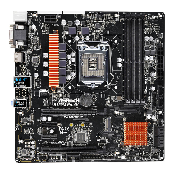
Page 11: Motherboard Layout
1.3 Motherboard Layout CPU_FAN1 ATX12V1 USB 2.0 T: USB5 B: USB6 USB 3.0 Top: T: USB5 RJ-45 B: USB6 B150M Combo-G CHA_FAN2 Front USB 3.0 PCIE1 PCI Express 3.0 CMOS Battery Intel B150 PCIE2 RoHS PCIE3 128Mb BIOS SPK_PLED PANEL1 USB1_2 USB3_4 SPEAKER... - Page 12 B150M Combo-G No. Description ATX 12V Power Connector (ATX12V1) CPU Fan Connector (CPU_FAN1) 2 x 288-pin DDR4 DIMM Slots (DDR4_A1, DDR4_B1) 2 x 240-pin DDR3/DDR3L DIMM Slots (DDR3_A1, DDR3_B1) ATX Power Connector (ATXPWR1) USB 3.0 Header (USB3_1_2) SATA Express Connector (SATAE_1) SATA3 Connector (SATA3_1) SATA3 Connector (SATA3_0) Chassis Fan Connector (CHA_FAN1)
-
Page 13: I/O Panel
1.4 I/O Panel No. Description No. Description PS/2 Mouse/Keyboard Port USB 3.0 Ports (USB3 _56) D-Sub Port USB 2.0 Ports (USB56) LAN RJ-45 Port* HDMI Port Line In (Light Blue)** DVI-D Port Front Speaker (Lime)** USB 3.0 Ports (USB3_34) Microphone (Pink)** * here are two LEDs on each LAN port. - Page 14 B150M Combo-G ** To conigure 7.1 CH HD Audio, it is required to use an HD front panel audio module and enable the multi- channel audio feature through the audio driver. Please set Speaker Coniguration to “7.1 Speaker”in the Realtek HD Audio Manager. Function of the Audio Ports in 7.1-channel Coniguration: Port Function...
-
Page 15: Chapter 2 Installation
Chapter 2 Installation his is a Micro ATX form factor motherboard. Before you install the motherboard, study the coniguration of your chassis to ensure that the motherboard its into it. Pre-installation Precautions Take note of the following precautions before you install motherboard components or change any motherboard settings. -
Page 16: Installing The Cpu
B150M Combo-G 2.1 Installing the CPU 1. Before you insert the 1151-Pin CPU into the socket, please check if the PnP cap is on the socket, if the CPU surface is unclean, or if there are any bent pins in the socket. Do not force to insert the CPU into the socket if above situation is found. - Page 18 B150M Combo-G Please save and replace the cover if the processor is removed. he cover must be placed if you wish to return the motherboard for ater service.
-
Page 19: Installing The Cpu Fan And Heatsink
2.2 Installing the CPU Fan and Heatsink... -
Page 20: Installing Memory Modules (Dimm)
B150M Combo-G 2.3 Installing Memory Modules (DIMM) his motherboard provides two 288-pin DDR4 (Double Data Rate 4) and two 240- pin DDR3/DDR3L (Double Data Rate 3) DIMM slots, and supports Dual Channel Memory Technology. Warning! It is NOT allowed to install a memory module into a DDR4 slot and a DDR3 slot simultaneously;... -
Page 22: Expansion Slots (Pci Express Slots)
B150M Combo-G 2.4 Expansion Slots (PCI Express Slots) here are 3 PCI Express slots on the motherboard. Before installing an expansion card, please make sure that the power supply is switched of or the power cord is unplugged. Please read the documentation of the expansion card and make necessary hardware settings for the card before you start the installation. -
Page 23: Jumpers Setup
2.5 Jumpers Setup he illustration shows how jumpers are setup. When the jumper cap is placed on the pins, the jumper is “Short”. If no jumper cap is placed on the pins, the jumper is “Open”. he illustration shows a 3-pin jumper whose pin1 and pin2 are “Short” when a jumper cap is placed on these 2 pins. -
Page 24: Onboard Headers And Connectors
B150M Combo-G 2.6 Onboard Headers and Connectors Onboard headers and connectors are NOT jumpers. Do NOT place jumper caps over these headers and connectors. Placing jumper caps over the headers and connectors will cause permanent damage to the motherboard. System Panel Header Connect the power PLED+ PLED-... - Page 25 SPEAKER Power LED and Speaker Please connect the DUMMY Header power LED and the DUMMY (7-pin SPK_PLED) chassis speaker to this (see p.6, No. 16) header. PLED+ PLED+ PLED- Serial ATA3 Connectors hese six SATA3 (SATA3_0) connectors support SATA (see p.6, No. 9) data cables for internal (SATA3_1) storage devices with up to...
- Page 26 B150M Combo-G USB 3.0 Header Besides four USB 3.0 Vbus Vbus (19-pin USB3_1_2) ports on the I/O panel, Vbus IntA_PB_SSRX- IntA_PA_SSRX- IntA_PB_SSRX+ (see p.6, No. 6) there is one header on this IntA_PA_SSRX+ IntA_PB_SSTX- motherboard. Each USB IntA_PA_SSTX- IntA_PB_SSTX+ IntA_PA_SSTX+ 3.0 header can support IntA_PB_D- two ports.
- Page 27 CPU Fan Connector his motherboard pro- FAN_VOLTAGE (4-pin CPU_FAN1) vides a 4-Pin CPU fan CPU_FAN_SPEED (see p.6, No. 2) FAN_SPEED_CONTROL (Quiet Fan) connector. If you plan to connect a 3-Pin CPU fan, please connect it to Pin 1-3. ATX Power Connector his motherboard pro- (24-pin ATXPWR1) vides a 24-pin ATX power...
- Page 28 B150M Combo-G TPM Header his connector supports Trusted (17-pin TPMS1) Platform Module (TPM) system, (see p.6, No. 19) which can securely store keys, digital certiicates, passwords, and data. A TPM system also helps enhance network security, protects digital identities, and ensures platform integrity.
-
Page 29: Tm Operation Guide
2.7 CrossFireX and Quad CrossFireX Operation Guide his motherboard supports CrossFireX and Quad CrossFireX that allows you to install up to three identical PCI Express x16 graphics cards. 1. You should only use identical CrossFireX -ready graphics cards that are AMD certiied. 2. - Page 30 B150M Combo-G Step 3 Connect a VGA cable or a DVI cable to the monitor connector or the DVI connec- tor of the graphics card that is inserted to PCIE1 slot.
-
Page 31: Driver Installation And Setup
2.7.2 Driver Installation and Setup Step 1 Power on your computer and boot into OS. Step 2 Remove the AMD drivers if you have any VGA drivers installed in your system. he Catalyst Uninstaller is an optional download. We recommend using this utility to un- install any previously installed Catalyst drivers prior to installation. -
Page 32: Chapter 3 Software And Utilities Operation
B150M Combo-G Chapter 3 Software and Utilities Operation 3.1 Installing Drivers he Support CD that comes with the motherboard contains necessary drivers and useful utilities that enhance the motherboard’s features. Running The Support CD To begin using the support CD, insert the CD into your CD-ROM drive. he CD automatically displays the Main Menu if “AUTORUN”... -
Page 33: Asrock Live Update & App Shop
Double-click on your desktop to access ASRock Live Update & APP Shop utility. *You need to be connected to the Internet to download apps from the ASRock Live Update & APP Shop. 3.2.1 UI Overview Category Panel Hot News... -
Page 34: Apps
B150M Combo-G 3.2.2 Apps When the "Apps" tab is selected, you will see all the available apps on screen for you to download. Installing an App Step 1 Find the app you want to install. he most recommended app appears on the let side of the screen. he other various apps are shown on the right. - Page 35 Step 3 If you want to install the app, click on the red icon to start downloading. Step 4 When installation completes, you can ind the green "Installed" icon appears on the upper right corner. To uninstall it, simply click on the trash can icon *he trash icon may not appear for certain apps.
- Page 36 B150M Combo-G Upgrading an App You can only upgrade the apps you have already installed. When there is an available new version for your app, you will ind the mark of "New Version" appears below the installed app icon. Step 1 Click on the app icon to see more details.
-
Page 37: Bios & Drivers
3.2.3 BIOS & Drivers Installing BIOS or Drivers When the "BIOS & Drivers" tab is selected, you will see a list of recommended or critical updates for the BIOS or drivers. Please update them all soon. Step 1 Please check the item information before update. Click on to see more details. -
Page 38: Setting
B150M Combo-G 3.2.4 Setting In the "Setting" page, you can change the language, select the server location, and determine if you want to automatically run the ASRock Live Update & APP Shop on Windows startup. -
Page 39: Enabling Usb Ports For Windows® 7 Installation
Requirements • A Windows® 7 installation disk or USB drive • USB 3.0 drivers (included in the ASRock Support CD or website) • A Windows® PC • Win7 USB Patcher (included in the ASRock Support CD or website) Scenarios... - Page 40 Select the “Win7 Folder” from Step1 by clicking the red circle as shown as the picture below. Step 4 Select the “USB Driver Folder” by clicking the red circle as shown as the picture below. If you are using ASRock’s Support CD for the USB 3.0 driver, please select your CD-ROM.
- Page 41 Step 5 Select where to save the ISO ile by pressing the red circle as shown as the picture below. Step 6 If you want to burn the patched image to a CD, please check “Burn Image” and select “Target Device to Burn”.
-
Page 42: Chapter 4 Uefi Setup Utility
B150M Combo-G Chapter 4 UEFI SETUP UTILITY 4.1 Introduction his section explains how to use the UEFI SETUP UTILITY to conigure your system. You may run the UEFI SETUP UTILITY by pressing <F2> or <Del> right ater you power on the computer, otherwise, the Power-On-Self-Test (POST) will continue with its test routines. -
Page 43: Navigation Keys
4.1.2 Navigation Keys Use < > key or < > key to choose among the selections on the menu bar, and use < > key or < > key to move the cursor up or down to select items, then press <Enter>... -
Page 44: Main Screen
B150M Combo-G 4.2 Main Screen When you enter the UEFI SETUP UTILITY, the Main screen will appear and display the system overview. Favorite Display your collection of BIOS items. Press F5 to add/remove your favorite items. -
Page 45: Oc Tweaker Screen
4.3 OC Tweaker Screen In the OC Tweaker screen, you can set up overclocking features. Because the UEFI sotware is constantly being updated, the following UEFI setup screens and descriptions are for reference purpose only, and they may not exactly match what you see on your screen. -
Page 46: Long Duration Maintained
B150M Combo-G Long Duration Maintained Conigure the period of time until the CPU ratio is lowered when the Long Duration Power Limit is exceeded. Short Duration Power Limit Conigure Package Power Limit 2 in watts. When the limit is exceeded, the CPU ratio will be lowered immediately. - Page 47 precharge command and opening the next row. RAS# Active Time (tRAS) he number of clock cycles required between a bank active command and issuing the precharge command. Command Rate (CR) he delay between when a memory chip is selected and when the irst active command can be issued.
- Page 48 B150M Combo-G Four Activate Window (tFAW) he time window in which four activates are allowed the same rank. CAS Write Latency (tCWL) Conigure CAS Write Latency. Third Timing tREFI Conigure refresh cycles at an average periodic interval. tCKE Conigure the period of time the DDR4 initiates a minimum of one refresh command internally once it enters Self-Refresh mode.
- Page 49 Conigure between module write to read delay. tWRRD_dg Conigure between module write to read delay. tWRRD_dr Conigure between module write to read delay. tWRRD_dd Conigure between module write to read delay. tWRWR_sg Conigure between module write to write delay. tWRWR_dg Conigure between module write to write delay.
- Page 50 B150M Combo-G Write_Early_ODT Conigure Write_Early_ODT. tAONPD Conigure tAONPD. Conigure tXP. tXPDLL Conigure tXPDLL. tPRPDEN Conigure tPRPDEN. tRDPDEN Conigure tRDPDEN. twRPDEN Conigure twRPDEN. OREF_RI Conigure OREF_RI. tREFIx9 Conigure tREFIx9. txSDLL Conigure txSDLL. txs_ofset Conigure txs_ofset. tZQOPER Conigure tZQOPER. tMOD Conigure tMOD. ZQCS_period Conigure ZQCS_period.
-
Page 51: Advanced Setting
tZQCS Conigure tZQCS. Advanced Setting ODT WR (CH A) Conigure the memory on die termination resistors' WR for channel A. ODT WR (CH B) Conigure the memory on die termination resistors' WR for channel B. ODT PARK (CH A) Conigure the memory on die termination resistors' PARK for channel A. ODT PARK (CH B) Conigure the memory on die termination resistors' PARK for channel B. - Page 52 B150M Combo-G Save User Default Type a proile name and press enter to save your settings as user default. Load User Default Load previously saved user defaults.
-
Page 53: Advanced Screen
4.4 Advanced Screen In this section, you may set the conigurations for the following items: CPU Coniguration, Chipset Coniguration, Storage Coniguration, Super IO Conigura- tion, ACPI Coniguration, USB Coniguration and Trusted Computing. Setting wrong values in this section may cause the system to malfunction. UEFI Coniguration Active Page on Entry Select the default page when entering the UEFI setup utility. -
Page 54: Cpu Coniguration
B150M Combo-G 4.4.1 CPU Coniguration Active Processor Cores Select the number of cores to enable in each processor package. CPU C States Support Enable CPU C States Support for power saving. It is recommended to keep C3, C6 and C7 all enabled for better power saving. Enhanced Halt State (C1E) Enable Enhanced Halt State (C1E) for lower power consumption. -
Page 55: Intel Virtualization Technology
Intel Virtualization Technology Intel Virtualization Technology allows a platform to run multiple operating systems and applications in independent partitions, so that one computer system can function as multiple virtual systems. Hardware Prefetcher Automatically prefetch data and code for the processor. Enable for better performance. -
Page 56: Chipset Coniguration
B150M Combo-G 4.4.2 Chipset Coniguration Primary Graphics Adapter Select a primary VGA. VT-d Intel® Virtualization Technology for Directed I/O helps your virtual machine monitor better utilize hardware by improving application compatibility and reliability, and providing additional levels of manageability, security, isolation, and I/O performance. -
Page 57: Onboard Lan
PCH DMI ASPM Support his option enables/disables the ASPM support for all PCH DMI devices. Share Memory Conigure the size of memory that is allocated to the integrated graphics processor when the system boots up. IGPU Multi-Monitor Select disable to disable the integrated graphics when an external graphics card is installed. Select enable to keep the integrated graphics enabled at all times. -
Page 58: Storage Coniguration
B150M Combo-G 4.4.3 Storage Coniguration SATA Controller(s) Enable/disable the SATA controllers. SATA Aggressive Link Power Management SATA Aggressive Link Power Management allows SATA devices to enter a low power state during periods of inactivity to save power. It is only supported by AHCI mode. -
Page 59: Super Io Coniguration
4.4.4 Super IO Coniguration Serial Port Enable or disable the Serial port. Serial Port Address Select the address of the Serial port. PS2 Y-Cable Enable the PS2 Y-Cable or set this option to Auto. -
Page 60: Acpi Coniguration
B150M Combo-G 4.4.5 ACPI Coniguration Suspend to RAM Select disable for ACPI suspend type S1. It is recommended to select auto for ACPI S3 power saving. ACPI HEPT Table Enable the High Precision Event Timer for better performance. PS/2 Keyboard Power On Allow the system to be waked up by a PS/2 Keyboard. - Page 61 USB Keyboard/Remote Power On Allow the system to be waked up by an USB keyboard or remote controller. USB Mouse Power On Allow the system to be waked up by an USB mouse.
-
Page 62: Usb Coniguration
B150M Combo-G 4.4.6 USB Coniguration Legacy USB Support Enable or disable Legacy OS Support for USB 2.0 devices. If you encounter USB compatibility issues it is recommended to disable legacy USB support. Select UEFI Setup Only to support USB devices under the UEFI setup and Windows/Linux operating systems only. -
Page 63: Trusted Computing
4.4.7 Trusted Computing Security Device Support Enable or disable BIOS support for security device. -
Page 64: Tools
In order to prevent users from bypassing OMG, guest accounts without permission to modify the system time are required. UEFI Tech Service Contact ASRock Tech Service if you are having trouble with your PC. Please setup network coniguration before using UEFI Tech Service. Easy Driver Installer For users that don’t have an optical disk drive to install the drivers from our support... - Page 65 Boot Manager Enable/disable the Boot Manager. Boot Manager Timeout Enable/disable the Boot Manager Timeout. Timeout Seconds Conigure the number of seconds to wait for the Boot Manager. Dehumidiier Function If Dehumidiier Function is enabled, the computer will power on automatically to dehumidify the system ater entering S4/S5 state.
-
Page 66: Network Coniguration
Save UEFI iles in your USB storage device and run Instant Flash to update your UEFI. Internet Flash - DHCP (Auto IP), Auto ASRock Internet Flash downloads and updates the latest UEFI irmware version from our servers for you. Please setup network coniguration before using Internet Flash. -
Page 67: Hardware Health Event Monitoring Screen
4.6 Hardware Health Event Monitoring Screen his section allows you to monitor the status of the hardware on your system, including the parameters of the CPU temperature, motherboard temperature, fan speed and voltage. Fan-Tastic Tuning Select a fan mode for CPU Fans 1&2, or choose Customize to set 5 CPU temperatures and assign a respective fan speed for each temperature. - Page 68 B150M Combo-G Over Temperature Protection When Over Temperature Protection is enabled, the system automatically shuts down when the motherboard is overheated. Case Open Feature Enable or disable Case Open Feature to detect whether the chassis cover has been removed.
-
Page 69: Security Screen
4.7 Security Screen In this section you may set or change the supervisor/user password for the system. You may also clear the user password. Supervisor Password Set or change the password for the administrator account. Only the administrator has authority to change the settings in the UEFI Setup Utility. Leave it blank and press enter to remove the password. -
Page 70: Boot Screen
B150M Combo-G 4.8 Boot Screen his section displays the available devices on your system for you to conigure the boot settings and the boot priority. Fast Boot Fast Boot minimizes your computer's boot time. In fast mode you may not boot from an USB storage device. - Page 71 Full Screen Logo Enable to display the boot logo or disable to show normal POST messages. AddOn ROM Display Enable AddOn ROM Display to see the AddOn ROM messages or conigure the AddOn ROM if you've enabled Full Screen Logo. Disable for faster boot speed. Boot Failure Guard Message If the computer fails to boot for a number of times the system automatically restores the default settings.
- Page 72 B150M Combo-G CSM (Compatibility Support Module) Enable to launch the Compatibility Support Module. Please do not disable unless you’re running a WHCK test. If you are using Windows 8.1 64-bit and all of your devices support UEFI, you may also disable CSM for faster boot speed. Launch PXE OpROM Policy Select UEFI only to run those that support UEFI option ROM only.
-
Page 73: Exit Screen
4.9 Exit Screen Save Changes and Exit When you select this option the following message, “Save coniguration changes and exit setup?” will pop out. Select [OK] to save changes and exit the UEFI SETUP UTILITY. Discard Changes and Exit When you select this option the following message, “Discard changes and exit setup?”... -
Page 74: Contact Information
Contact Information If you need to contact ASRock or want to know more about ASRock, you’re welcome to visit ASRock’s website at http://www.asrock.com; or you may contact your dealer for further information. For technical questions, please submit a support request form at http://www.asrock.com/support/tsd.asp...
Need help?
Do you have a question about the Super Alloy B150M COMBO-G and is the answer not in the manual?
Questions and answers