Table of Contents
Advertisement
Service Manual
CS-C181KE / CU-C181KE
CS-C241KE / CU-C241KE
Contents
Features .......................................................... 1
Functions ................................................... 2 - 4
Product Specifications ............................... 5 - 8
Dimensions .............................................. 9 - 10
Refrigeration Cycle Diagram ......................... 10
Block Diagram ............................................... 11
Wiring Diagram .............................................. 12
Operation Details ................................... 13 - 19
Installation Information .......................... 20 - 21
3-way Valves ......................................... 22 - 28
Servicing Information ............................. 29 - 32
Troubleshooting Guide .......................... 33 - 34
Technical Data ....................................... 35 - 36
Exploded View ......................................... 37, 39
Replacement Parts List ........................... 38, 40
Electronic Parts List ....................................... 41
ORDER NO. MAC9806008C2
Room Air Conditioners
© 1998 Matsushita Air-Conditioning Corp. Sdn. Bhd.
(183914D)
All rights reserved. Unauthorized copying and distribu-
tion is a violation of law.
Advertisement
Table of Contents
Troubleshooting

Related Manuals for Panasonic CS-C181KE


Summary of Contents for Panasonic CS-C181KE
-
Page 1: Table Of Contents
ORDER NO. MAC9806008C2 Service Manual Room Air Conditioners CS-C181KE / CU-C181KE CS-C241KE / CU-C241KE Contents Features ............1 Functions ........... 2 – 4 Product Specifications ....... 5 – 8 Dimensions ..........9 – 10 Refrigeration Cycle Diagram ......10 Block Diagram ..........11 Wiring Diagram .......... -
Page 2: Features
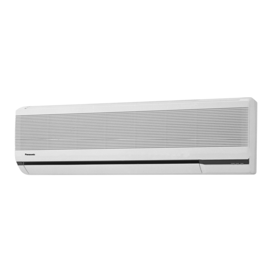
CS-C181KE WARNING This service information is designed for experienced repair technicians only and is not designed for use by the general public. It does not contain warnings or cautions to advise non-technical individuals of potential dangers in attempting to service a product. Products powered by electricity should be serviced or repaired only by experienced professional technicians. -
Page 3: Functions
CS-C181KE Functions Remote Control OFF / ON I TEMP. Operation OFF / ON Room Temperature Setting • Temperature Setting (16˚C to 30˚C) • Automatic Operation MODE Operation Mode Selection 2˚C lower than standard Standard • Automatic Operation Mode AUTO •... - Page 4 CS-C181KE Functions Indoor Unit POWER I Power Switch OFF / ON Auto Restart Control • Operation is restarted after power failure AUTO at previous setting mode. OFF / ON Temporary Operation Switch Anti-Freezing Control • Used when the remote control cannot be used.
-
Page 5: Functions
CS-C181KE Functions Outdoor Unit Overload Protector • Inner protector 60 Secs. Forced Operation Control • Once the compressor is activated, it does not stop for 60 secs. (Stops immediately with remote control stop signal.) Outdoor Fan Operation Control • 4-pole induction motor (2-speed) •... -
Page 6: Product Specifications
CS-C181KE Product Specifications Unit CU-C181KE CS-C181KE 5.40 - 5.30 Cooling Capacity Btu/h 18,400 - 18,100 Moisture Removal Pint/h Phase Single Power Source 240 - 220 Cycle SIDE VIEW TOP VIEW OUTLET Airflow Method INTAKE Air Volume Indoor Air (Lo) 11.2 (400) /min (cfm) –... - Page 7 CS-C181KE Product Specifications Unit CS-C181KE CU-C181KE Heat Evaporator Description Condenser Exchanger Tube material Copper Copper Fin material Aluminium Aluminium Fin Type Slot Fin Corrugated Fin Row / Stage (Plate fin configuration, forced draft) 2 × 14 2 × 31 775.2 Size (W ×...
- Page 8 CS-C181KE Product Specifications Unit CU-C241KE CS-C241KE 6.65 - 6.60 Cooling Capacity Btu/h 22,700 - 22,500 Moisture Removal Pint/h Phase Single Power Source 240 - 220 Cycle SIDE VIEW TOP VIEW OUTLET Airflow Method INTAKE Air Volume Indoor Air (Lo) 13.5 (480) /min (cfm) –...
-
Page 9: Product Specifications
CS-C181KE Product Specifications Unit CS-C241KE CU-C241KE Evaporator Description Condenser Heat Tube material Copper Copper Exchanger Fin material Aluminium Aluminium Fin Type Slot Fin Corrugated Fin Row / Stage (Plate fin configuration, forced draft) 2 × 14 2 × 26 769.2 Size (W ×... -
Page 10: Dimensions
CS-C181KE Dimensions CS-C181K / CS-C241K <Top View> <Front View> Air intake direction Right piping hole Approx 2,100 Air outlet direction <Side View> Left piping hole Lower piping hole 48.5 Remote control transmitter Installation plate hooks Drain ports Gas side Liquid side Approx. -
Page 11: Dimensions
CS-C181KE Dimensions CU-C181K / CU-C241K Required space for installation 56.3 Air intake direction 10cm 10cm 70cm Anchor bolt pitch 280 x 570 Air outlet direction Slots (12 x 17) Four places 3-way valve at liquid side 3-way valve at gas side... -
Page 12: Block Diagram
CS-C181KE Block Diagram CS-C181KE / CU-C181KE CS-C241KE / CU-C241KE – 11 –... -
Page 13: Wiring Diagram
CS-C181KE Wiring Diagram CS-C181KE / CU-C181KE CS-C241KE / CU-C241KE WIRELESS ELECTRONIC REMOTE CONTROLLER 220-240V, 50Hz CONTROL POWER SUPPLY CORD RECEIVER DISPLAY LAMP CN-DISP (WHT) REMOTE CONTROL No. ELECTRONIC CONTROLLER REMARKS: : BLUE : BROWN MOTOR : BLACK : WHITE PUMP DOWN SW... -
Page 14: Operation Details
CS-C181KE Operation Details 1) Cooling Mode Operation Cooling in operation according to Remote Control setting. Time Delay Safety Control (3 minutes) • When the compressor is stopped by Power Switch, Remote Control or there is a power failure, it restarts after 3 minutes when the Power Switch, Remote Control is turned ON or the power supply is resumed. -
Page 15: Indoor Fan
CS-C181KE Operation Details Automatic Fan Speed Mode When Automatic Fan Speed is selected at Remote Control during cooling operation. • Fan speed rotates in the range of Hi to Me. • Deodorizing Control. Indoor stop stop stop stop 40" 20"... - Page 16 CS-C181KE Operation Details 2) Soft Dry Mode Operation • The unit starts cooling operation until the room temperature reaches the setting temperature set on the Remote Control, and then Soft Dry operation will start. • During Soft Dry operation, the Indoor Fan will operate and stop at 4-second intervals at low speed.
-
Page 17: Outdoor Fan
CS-C181KE Operation Details Soft Dry Operation Time Diagram a b c d e f g h i j k l m n o p q r s t u v Intake Air Temperature Cooling ON 1.5°C Cooling OFF Set Temp. - Page 18 CS-C181KE Operation Details 3) Air Circulation Mode Operation • When the temperature near the ceiling reaches the setting temperature, Air Circulation Mode operation commences at low airflow volume. It stops when the temperature drops to 2°C below the setting temperature.
- Page 19 CS-C181KE Operation Details 5) Sleep Mode Auto Operation Cooling or Soft Dry Operation When you press the SLEEP Mode, the following move- Approx. 0.5°C increase ment will start to avoid overcooling. TEMP. • When the room temperature reaches the setting Approx.
-
Page 20: Operation Details
CS-C181KE Operation Details 8) Airflow Direction Control Airflow Direction Auto-Control • When set a Airflow Direction Auto-Control with Horizontal remote control, the louver swings up and down as Upper limit shown in the diagram. 34° • The louver does not swing when the Indoor Fan Swing up and down stops during operation. -
Page 21: Installation Information
CS-C181KE Installation Information Attached accessories Accessories part Qty. Accessories part Qty. Remote control Installation plate Installation plate fixing screw Battery Vinyl tape Air purifiying filter Vinyl tape Band Accessories: Flaring piping kit CZ-4F5, 7, 10AN (C181K) CZ-52F5, 7, 10AN (C241K) -
Page 22: Installation Information
CS-C181KE Installation Information Indoor / Outdoor unit installation diagram Length of power supply cord Piping direction Attention not to bend up drain hose (Front side) about 1 m about 2 m Right Right < < < < rear Left Left... - Page 23 CS-C181KE 3-way Valve 3-way Valve (Liquid Side) 3-way Valve (Gas Side) Valve cap Flare nut Hexagonal wrench(4 mm) Open position Flare nut Open position Closed position Closed position piping piping connection connection Service port Service port Service Service port cap...
-
Page 24: 3-Way Valves
CS-C181KE 1 Evacuation of Installation When installing an air conditioner, be sure to evacuate the air inside the indoor unit and pipes in the following procedure. Required tools: hexagonal wrench, adjustable wrench, The air in the indoor unit and in the piping must be torque wrenches, wrench to hold the purged. -
Page 25: Pumping Down
CS-C181KE 2 Pumping down (Indoor unit) (Liquid side) (Outdoor unit) 3-way valve Close (Gas side) 3-way valve CLOSE Open Refrigerant Reclaiming Equipment CLOSE Procedure: (1) Confirm that both the 3-way valves are set to the (6) Operate the air conditioner at the cooling cycle open position. - Page 26 CS-C181KE 3 Evacuation of Re-installation WHEN RE-INSTALLING AN AIR CONDITIONER, BE If air remains in the indoor unit and refrigeration SURE TO EVACUATE THE AIR INSIDE THE INDOOR pipes, it will affect the compressor, reduce to cooling UNIT AND PIPES in the following procedure.
- Page 27 CS-C181KE 4 Balance refrigerant of the 3-way valves (Lack of refrigerant in the refrigeration cycle) (Indoor unit) (Liquid side) (Outdoor unit) 3-way valve Open (Gas side) 3-way valve OPEN Open Refrigerant Reclaiming Equipment OPEN Procedure: (1) Confirm that both the 3-way valves are set to the opened position.
- Page 28 CS-C181KE 5 Evacuation (No refrigerant in the refrigeration cycle) (Indoor unit) (Liquid side) (Outdoor unit) 3-way valve Open (Gas side) 3-way valve OPEN Open Vacuum pump OPEN Procedure: (1) Connect the vacuum pump to the charge set’s centre hose. (2) Turn on the vaccuum pump to evacuate the unit.
- Page 29 CS-C181KE 6 Gas charging (After Evacuation) (Indoor unit) (Liquid side) (Outdoor unit) 3-way valve Open (Gas side) 3-way valve Check valve CLOSE Open Charging cylinder OPEN Procedure: (5) Mount the valve stem nuts and the service port (1) Connect the charge hose to the charging cylinder.
-
Page 30: Servicing Information
CS-C181KE Servicing Information (A) Disassembly of the parts Electronic Inspection points for the Indoor Electronic Controller Controller 1. The Electronic Controller, a signal Receiver and an Indicator can be seen by removing the Front Grille and Control Board Cover, as shown in the Fig. 1. - Page 31 CS-C181KE Servicing Information 3. Remove the Discharge Grille. Remove the Discharge Grille by taking off the 3 screws that hold the Discharge Grille and then pull the Discharge Grille in a down and forward direction. Screws Fig. 5 Fan Motor 4.
- Page 32 CS-C181KE Servicing Information Cross Flow Fan Removal Procedure 1. Remove the Fan Mounting Screws and Bearing. (Refer to No. 4 of Indoor Fan Motor the removal procedure) 2. Loosen the 2 screws mounted at the left side of the evaporator.
-
Page 33: Servicing Information
CS-C181KE Servicing Information Reset terminal (B) Remote Control Transmission Setting • Remote Control Reset When the batteries are inserted for the first time, or the batteries are replaced, all the indications will blink and the remote control might not work. -
Page 34: Troubleshooting Guide
CS-C181KE Troubleshooting Guide Refrigeration cycle system In order to diagnose malfunctions, make sure that Normal Pressure and Outlet Air Temperature (Standard) there are no electrical problems before inspect- ing the refrigeration cycle. Such problems include Gas pressure Outlet air temperature... -
Page 35: Troubleshooting Guide
CS-C181KE Troubleshooting Guide 1. Relationship between the condition of the air conditioner and pressure and electric current Cooling Mode Condition of the air Low Pressure High Pressure Electric current during operation conditioner Insufficient refrigerant (gas leakage) Clogged capillary tube or Strainer... -
Page 36: Technical Data
CS-C181KE Technical Data L L L L L Thermostat characteristics CS-C181K / CS-C241K • Soft Dry • Cooling (°C) (°C) COMP. ON Cooling ON COMP. OFF = Set Temperature Cooling OFF = Set Temperature Soft Dry OFF, Soft Dry ON Diff. -
Page 37: Technical Data
CS-C181KE Technical Data L L L L L Operation characteristics CS-C181K / CU-C181K • Cooling Characteristic • Piping Length Characteristic 220V 220V 240V 240V 12.5 11.5 12.5 11.5 OUTDOOR ROOM TEMPERATURE (°C) PIPING LENGTH (m) [Condition] Room temperature: 27/19°C [Condition] Room temperature: 27/19°C Cooling operation: At High fan Outdoor temperature: 35/24°C... -
Page 38: Exploded View
CS-C181KE Exploded View CS-C181KE / CS-C241KE " & > – 37 –... -
Page 39: Replacement Parts List
CS-C181KE Replacement Parts List <Model: CS-C181KE / CS-C241KE> REMARKS DESCRIPTION & NAME CS-C181KE CS-C241KE CHASSY COMPLETE CWD50C265 CHASSY BACK COVER CWD93956 FAN MOTOR CWA92270 CWA92287 CWH02C058 CROSS FLOW FAN COMPLETE SCREW – CROSS FLOW FAN CWH4580304 BEARING ASS’Y CWH64K007 EVAPORATOR... -
Page 40: Exploded View
CS-C181KE Exploded View CU-C181KE / CU-C241KE < & " > – 39 –... - Page 41 CS-C181KE Replacement Parts List <Model: CU-C181KE / CU-C241KE> REF. DESCRIPTION & NAME CU-C181KE CU-C241KE REMARKS ← CHASSY ASS’Y CWD50K514B ← SOUND PROOF BOARD CWH15223 ← FAN MOTOR BRACKET CWD54145 ← SCREW - FAN MOTOR BRACKET CWH55101 ← PARTICULAR PLATE F/M (L) CWD90835 ←...
-
Page 42: Electronic Parts List
CS-C181KE Electronic Parts List <Model: CWA741180> SYMBOL DESCRIPTION & NAME PART NO. DIODE A54RA15–01V3 DIODE A54CS1VB20E ZENAR DIODE A54D7.5EL1TB ZNR1, ZNR2 A54C352 TRANSISTOR A55C1741ASTR A55DTC114EST TRANSISTOR A55DTC143XST TRANSISTOR TRANSISTOR Q4, Q5 A55C1740STPQ INTEGRATED CIRCUIT A52D0001W015 INTEGRATED CIRCUIT A52C040 INTEGRATED CIRCUIT... - Page 43 CS-C181K/C241K CS-C181K/C241K CS-C181K/C241K ELECTRONIC CIRCUIT DIAGRAM • CS-C181K / CU-C181K SERIES • CS-C241K / CU-C241K SERIES BLUE AC220-240V YELLOW 50Hz/60Hz SINGLE PHASE TRANSFORMER A40C246 TEMPERATURE POWER FUSE TEMPERATURE SUPPLY FUSE 113°C 102°C SWITCH ELECTRONIC CIRCUIT (XH-3) BLUE CN-FUSE CN-T CN-FUSE1 AUTO MODE TEMP.
- Page 44 CS-C181K/C241K CS-C181K/C241K CS-C181K/C241K How to use electronic circuit diagram ELECTRONIC CIRCUIT DIAGRAM PRINT PATTERN • INDOOR UNIT PRINTED CIRCUIT BOARD Before using the circuit diagram, read the following carefully. REMOTE CONTROL * Voltage measurement * Indications for capacitor Voltage has been measured with a digital a.
- Page 45 Printed in Malaysia MACC P980702500YW...