Advertisement
Quick Links
Download this manual
See also:
Instruction Manual
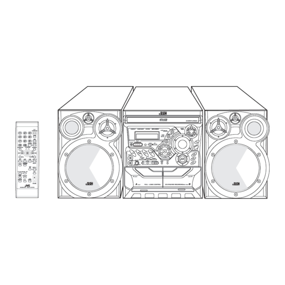
SERVICE MANUAL
COMPACT COMPONENT SYSTEM
Contents
Safety precautions ----------------------------- 1- 2
Important for laser products ------------------ 1- 3
Preventing static electricity ------------------- 1- 4
Disassembly method -------------------------- 1- 5
Adjustment method --------------------------- 1-18
MX-K350V
©
COPYRIGHT
2001VICTOR COMPANY OF JAPAN, LTD.
Flow of functional
operation until TOC read --------------- 1-20
Maintenance of laser pickup ---------------- 1-21
Replacement of laser pickup ---------------- 1-21
Description of major ICs --------------------- 1-22
MX-K350V
Area Suffix
US .................. SINGAPORE
UX .................. SAUDI
No.21166
Dec.2002
Advertisement

Related Manuals for JVC MX-K350V


Summary of Contents for JVC MX-K350V
- Page 1 MX-K350V SERVICE MANUAL COMPACT COMPONENT SYSTEM MX-K350V Area Suffix US ....SINGAPORE UX ....SAUDI Contents Flow of functional Safety precautions ----------------------------- 1- 2 operation until TOC read --------------- 1-20 Important for laser products ------------------ 1- 3 Maintenance of laser pickup ---------------- 1-21...
- Page 2 Safety Precautions 1. This design of this product contains special hardware and many circuits and components specially or safety purposes. For continued protection, no changes should be made to the original design unless authorized in writing by the manufacturer. Replacement parts must be identical to those used in the original circuits.
- Page 3 Important for laser products 1. CLASS 1 LASER PRODUCT 5. CAUTION : If safety switches malfunction, the laser is able to function. 2. DANGER : Invisible laser radiation when open and inter lock failed or defeated. Avoid direct exposure to beam. 6.
- Page 4 Preventing static electricity 1. Grounding to prevent damage by static electricity Electrostatic discharge (ESD), which occurs when static electricity stored in the body, fabric, etc. is discharged, can destroy the laser diode in the traverse unit (optical pickup). Take care to prevent this when performing repairs.
- Page 5 Disassembly method Commence disassembly of this set by removing the main units and then proceed to the components and assemblies inside the units. Replacement of the fuses and the power IC Top cover CD changer unit Front panel assembly Chassis unit CD changer unit Removing the main PCB Removing the CD changer mechanism assembly...
- Page 6 <Disassembly of the main blocks of this set> Replacing the power IC (See Fig.2 ) Prior to performing the following procedure, remove Replacement of the fuses and the power IC the top cover. 1. Remove the two screws “ A ” from the heat sinkbetween Replacing the fuses (See Fig.1, Fig.3) the power IC.
- Page 7 Removing the top cover and two sides BOARD (See Fig.4 and 5) 1. Remove the six screws “ B ” that retain the top cover from the rear of the body. 2. Remove the eight screws “ C ” and “ D ” that retain the top from the two sides of the body.
- Page 8 Removing the CD changer unit (See Fig.6 and 9) Prior to performing the following procedures, remove the top cover and both sides BOARD. [Caution] Although the CD mechanism unit can be removed without removing the CD tray panel, it is still recommended to remove it in order to prevent damage.
- Page 9 Removing the front panel assembly (See Fig.10 and 11) Prior to performing the following procedures, remove the top cover and both sides board. Also remove the CD changer unit. 1. Disconnect the parallel wire and card wire from the connectors CN702, CN701, CN703, CN850 on the power amp and supply PCB.
- Page 10 <Disassembly of units and assembly inside this set> Removing the CD PCB (See Fig.12 and 13) Prior to performing the following procedures, remove the top cover and both sides board. Also remove the CD changer unit. 1. The two screws “ E ” that retain the VCD assembly should be removed.
- Page 11 Removing the CD changer mechanism assembly (See Fig.14 and 16) Prior to performing the following procedures, remove the top cover and both sides board. Also remove the CD changer unit. 1. Remove the screws “ d ” from the front chuch base of the CD changer mechanism unit.
- Page 12 Removing the CD PCB (See Fig.17) Prior to performing the following procedures, remove the top cover and both sides board. Also remove the CD changer unit. Also remove the CD changer mechanism. 1. Widen the section “ f ” . 2.
- Page 13 Removing the cassette deck mechanism (See Fig.21) Prior to performing the following procedure, remove the top cover and both sides board. Also remove the CD changer unit. Also remove the front panel assembly. 1. Remove the five screws “ Z ” retaining the cassette deck mechanism.
- Page 14 Removing the switch PCB and sound mode and CD function switch PCB (See Fig.23 to 26) Prior to performing the following procedures, remove the top cover and both sides board. Also remove the CD changer unit. Also remove the front panel assembly. 1.
- Page 15 Removing the cassette deck main motor, and replacing the main belts (See Fig. 21, 27 and 28) Prior to performing the following procedures, remove the top cover and both sides board. Also remove the CD changer unit. Also remove the front panel assembly. 1.
- Page 16 Removing the cassette deck heads Removing the 3-pin regulator (See Fig.21 to 30) (See Q904, Q907, 31) Prior to performing the following procedures, remove Prior to performing the following procedures, remove the top cover and both sides board. the top cover and both sides board. Also remove the CD changer unit.
- Page 17 2. Pull out the heat sink cover toward you. 3. Remove four(CA-MXK350V) screws “ AA” form the MX-K350V back panel between the heat sink. 4. Remove the three screws “ X ” that retain the speaker terminals and aux terminal.
- Page 18 Adjustment method Adio input signal Measurement instruments required for adjustment AM modulation frequency : 400Hz Modulation factor : 30% 1. Low frequency oscillator FM modulation frequency : 400Hz This oscillator should have a capacity to output 0dB Frequency displacement : 22.5kHz to 600ohm at an oscillation frequency of 50Hz- 20kHz.
- Page 19 Arrangement of adjusting positions Tape recorder section Measurement Standard Adjusting Items Measurement method conditions values positions Cassette Head Test tape : 1. Playback the test tape VT703 (10KHz) or equivalent. Maximum output Adjust the VT703 (10kHz) Azimuth Alignments head azimuth 2.
- Page 20 Flow of functional operation until TOC read 1-20...
- Page 21 Maintenance of laser pickup Replacement of laser pickup (1) Cleaning the pick up lens Before you replace the pick up, please try to clean the lens with a alcohol soaked cotton swab. (2) Life of the laser diode When the life of the laser diode has expired, the following symptoms will appear.
- Page 22 Description of major ICs n VIDEO CD PROCESSOR CHIP PINOUT n VIDEO PC PROCESSOR CHIP PIN DESCRIPTION 1-22...
- Page 23 VIDEO CD COMPANION CHIP 1. Pinout 1-23...
- Page 24 2. Pin description 1-24...
- Page 25 BA15218/BA15218F(IC102/IC852): Dual operational amplifier 1. Terminal layout & block diagram BA3837(IC103): MIC Mixer 1. Terminal layout & block diagram 2. Pin function BU9253AS(IC851): Low pass filter & echo mixer 1. Terminal layout & block diagram 2. Pin function 1-25...
- Page 26 TA8189N (IC401) : REC/PB amp. 1. Terminal layout 2. Block diagram 3. Pin function 1-26...
- Page 27 TC74HC4094AP (IC402) : 8-bit shift and store resister 1. Terminal layout 2. Block diagram 1-27...
- Page 28 TDA7440D (IC101) : Audio processor 1. Terminal layout 2. Block diagram 1-28...
- Page 29 < M E M O >...
- Page 30 MX-K350V VICTOR COMPANY OF JAPAN, LIMITED AUDIO & COMMUNICATION BUSINESS DIVISION PERSONAL & MOBILE NETWORK B.U.10-1, 1 Chome, Ohwatari-machi, maebashi-city, 371-8543, Japan Printed in Japan No.21166 200212...
- Page 31 A rea S uffix S upplement US --------------- Singapore UX ----------- Saudi Arabia Because there were many mistake to the Service Manual MX-K350V (No.21166,Page 3-3 to 3-21 on PARTS LIST.),please this supplementally for servicing. N o .21166B M ay .2003 COPYRIGHT 2002 VICTOR COMPANY OF JAPAN, LTD.
- Page 32 MX-K350V VICTOR COMPANY OF JAPAN, LI MITED AV & MALUTIMEDIA COMPANY AUDIO/VIDEO SYSTEM CATEGORY. 10-1,1chome,Ohwatari-machi,Maebashi-city,371-8543,Japan N o .21166B 200305...
- Page 33 MX-K350V SCHEMATIC DIAGRAMS COMPACT COMPONENT SYSTEM MX-K350V CD-ROM No.SML200212 Area suffix US ------------- Singapore UX ---------- Saudi Arabia 3-CD PLAY & EXCHANGE CD-R/RW PLAYBACK SOUND COMPACT COMPONENT SYSTEM MX-K350V MODE REPEAT 1 BIT STANDBY/ON DUAL D/A CONVERTER PROGRAM SLEEP RANDOM...
- Page 34 MX-K350V In regard with component parts appearing on the silk-screen printed side (parts side) of the PWB diagrams, the parts that are printed over with black such as the resistor ( diode ( ) and ICP ( ) or identified by the " " mark nearby are critical for safety.
- Page 35 MX-K350V Block diagram...
- Page 36 MX-K350V MX-K350V Standard schematic diagrams CD Servo Control Section K350V...
- Page 37 MX-K350V Power transformer section K350V MIC AMP. and H.P section...
- Page 38 MX-K350V MX-K350V FL Display and CPU Control Section...
- Page 39 MX-K350V Head AMP. audio, power AMP. and power Supply...
- Page 40 MX-K350V MX-K350V MPEG Section...
- Page 41 MX-K350V Tuner Section...
- Page 42 MX-K350V MX-K350V Remote Control Section...
- Page 43 MX-K350V Printed circuit boards Main /power-amp. circuit board (Top side ) K350V...
- Page 44 MX-K350V MX-K350V Main / power-amp. circuit board(Botton side ) K350V 2-10...
- Page 45 MX-K350V CD Main. circuit board (Top side) K350V CD Main. circuit board (Bottom side) K350V 2-11...
- Page 46 MX-K350V MX-K350V Display/Uicom control. circuit board (Top side) K350V 2-12...
- Page 47 MX-K350V Display/Uicom control. circuit board (Bottom side) K350V 2-13...
- Page 48 MX-K350V MX-K350V MPEG. circuit board (Top side) K350V MPEG. circuit board (Bottom side) K350V 2-14...
- Page 49 MX-K350V Tuner. circuit board (Top side) K350V 2-15...
- Page 50 MX-K350V VICTOR COMPANY OF JAPAN, LIMITED AUDIO & COMMUNICATION BUSINESS DIVISION PERSONAL & MOBILE NETWORK BUSINESS UNIT. 10-1,1chome,Ohwatari-machi,Maebashi-city,371-8543,Japan Printed in Japan 200212 No.21166SCH...
-
Page 51: Table Of Contents
MX-K350V PARTS LIST [ MX-K350V ] * All printed circuit boards and its assemblies are not available as service parts. Area suffix US ---------------------- Singapore UX ------------------- Saudi Arabia - Contents - 3- 3 Exploded view of general assembly and parts list (Block No.M1) 3- 5 CD changer mechanism assembly and parts list (Block No.MA) - Page 52 MX-K350V < M E M O >...
- Page 53 MX-K350V Exploded view of general assembly and parts list Block No.
- Page 54 MX-K350V MX-K350V Parts list (General assembly) Parts list (General assembly) Block No. M1MM Block No. M1MM Item Parts number Parts name Q'ty Description Area Item Parts number Parts name Q'ty Description Area BI109808010101 WINDOW CASS L BI202267010101 BRACKET HLDR VFD...
-
Page 55: Cd Changer Mechanism Assembly And Parts List (Block No.ma)
MX-K350V CD changer mechanism assembly and parts list Block No. - Page 56 MX-K350V MX-K350V Parts list (CD changer mechanism) Parts list (CD changer mechanism) Block No. MAMM Block No. MAMM Item Parts number Parts name Q'ty Description Area Item Parts number Parts name Q'ty Description Area BI3199801000 GEAR PLATE BI86000115F1 SCREW 2 M2.0X12.0...
-
Page 57: Cassette Mechanism Assembly And Parts List (Block No.mp)
MX-K350V Cassette mechanism assembly and parts list Block No. CMAT6Z219A L SIDE TYPE L SIDE R SIDE R SIDE TYPE Note: Parts listed on the Parts List below can be supplied. However, parts that are not listed below cannot be supplied individually but only by purchasing the whole Cassette Mechanism Assembly Unit. -
Page 58: Packing Materials And Accessories Parts List (Block No.m3,M5)
MX-K350V Packing materials and accessories parts list Block No. Block No. Note / Depending on the Video CD to be used the VCD NUMBER + or VCD NUMBER Ð button on the Unit does not work properly. In this case, when the button is used, ÒINV ALIDÓ is displayed. - Page 59 MX-K350V Parts list (Packing) Block No. M3MM Item Description Parts number Parts name Q'ty Area BI4312641 CARTON BOX BI4511363 POLY FOAM L POLY FOAM R BI4511373 BI4005355 POLY BAG 2 REMOTE&AC CORD BI4710321 POLY BAG 1 UNIT BI4511451 EPE FOAM PAPER...
-
Page 60: Area Suffix
MX-K350V PARTS LIST [ MX-K350V ] * All printed circuit boards and its assemblies are not available as service parts. Area suffix US ---------------------- Singapore UX ------------------- Saudi Arabia - Contents - 3- 3 Exploded view of general assembly and parts list (Block No.M1) 3- 5 CD changer mechanism assembly and parts list (Block No.MA) - Page 61 MX-K350V < M E M O >...
- Page 62 MX-K350V Exploded view of general assembly and parts list (K350V) Block No.
- Page 63 MX-K350V MX-K350V Parts list (Exploded view of general assembly) ltem Parts number Parts name Q'ty Description Area ltem Parts number Parts name Q'ty Description Area BI109808010101 WINDOW, CASS L BI202267010101 BRACKET HLDR-VFD BI109809010101 WINDOW, CASS R PWB-VFD 251099G01V BI109806010201 BOX, CASS L...
- Page 64 MX-K350V CD changer mechanism assembly and parts list Block No. 52 X4...
- Page 65 MX-K350V MX-K350V Cassette mechanism assembly and parts list Electrical parts list ( K350V-CD Changer ) Block No. CMAT6Z219A Item Parts number Parts name Q'ty. Description Area Location BI3199801000 GEAR PLATE BI3199802000 GUIDE PLATE BI3199804002 UP COVER PLATE BI3499801000 SHAFT PULLEY...
- Page 66 MX-K350V Electrical parts list (CD selection) Block No. 01 Item Parts number Parts name Remarks Area Item Parts number Parts name Remarks Area CN601 12S160031 CONNECTOR 16P/1.0MM C660 QETM1CM-106 E CAPACITOR 10UF M 16V CN602 23S600961 CONNECTOR 6P/PITCH2.0MM C661 QETM1HM-335 E CAPACITOR 3.3UF M 50V...
- Page 67 MX-K350V Electrical parts list (CD selection) Block No. 01 Item Parts number Parts name Remarks Area R634 QRE141J-103 C RESISTOR 10K J 1/4W R635 QRE141J-473 C RESISTOR 47K J 1/4W R637 QRE141J-332 C RESISTOR 3.3K J 1/4W R638 QRE141J-222 C RESISTOR 2.2K J 1/4W...
- Page 68 MX-K350V Electrical parts list Block No. 02 (Front disply uicom selection) Item Remarks Item Remarks Parts number Parts name Area Parts number Parts name Area ----- 251173G01V FRONT B 350V RA705 NRSA63J-473X MG RESISTOR 47K J 1/16W ----- 202267010101 HOLDER VFD...
- Page 69 MX-K350V Electrical parts list Block No. 02 (Front disply uicom selection) Item Parts number Parts name Remarks Area Item Parts number Parts name Remarks Area R710 NRSA63J-473X MG RESISTOR 47K J 1/16W R774 NRSA63J-102X MG RESISTOR 1K J 1/16W R711...
- Page 70 MX-K350V Electrical parts list (Tuner selection) Block No. 03 Item Parts number Parts name Remarks Area Item Parts number Parts name Remarks Area ----- QCFB1HZ-473 C CAPACITOR 0.047UF Z 50V 11ES2-T4 SI DIODE ----- 202304010101 HOLDER 0.5MM 11ES2-T4 SI DIODE...
- Page 71 MX-K350V Electrical parts list (Tuner selection) Block No. 03 Item Parts number Parts name Remarks Area QRE141J-473 C RESISTOR 47K J 1/4W QRE141J-102 C RESISTOR 1K J 1/4W QRE141J-102 C RESISTOR 1K J 1/4W QRE141J-102 C RESISTOR 1K J 1/4W...
- Page 72 MX-K350V Electrical parts list (VCD changer) Block No. 04 Item Parts number Parts name Remarks Area Item Parts number Parts name Remarks Area ----- 202454010101 GRD VIDEO SPTE T=0.5MM L1108 26033000KM0024 FIXED INDUCTOR 3.3UH ----- 11AT370B9 BLACK WIRE WITH 1.3MM...
- Page 73 MX-K350V Block No. 04 Electrical parts list (VCD changer) Item Parts number Parts name Remarks Area W1104 5283A TIN COATED 0.6MM X1101 2102401 CRYSTAL COMMUTER 3-14...
- Page 74 MX-K350V Electrical parts list (Main) Block No. 05 Item Parts number Parts name Remarks Area Item Parts number Parts name Remarks Area ----- RT000611B3 RH/TS 3XL8MM C219 NDC31HJ-471X C CAPACITOR 470PF J 50V ----- 201771010101 INTERNAL TOOTH M2.6 C220 NDC31HJ-221X...
- Page 75 MX-K350V Electrical parts list (Main) Block No. 05 Item Parts number Parts name Remarks Area Item Parts number Parts name Remarks Area C381 NCF31HZ-223X C CAPACITOR 0.022UF Z 50V C903 QFLA2AJ-683 M CAPACITOR 0.068UF J 100V C382 QETM1HM-104 E CAPACITOR 0.1UF M 50V...
- Page 76 MX-K350V Electrical parts list (Main) Block No. 05 Item Parts number Parts name Remarks Area Item Parts number Parts name Remarks Area FB304 18A843556N0002 F-BEAD 52MM Q314 DTC114YSA-T D.TRANSISTOR FB306 18A843556N0002 F-BEAD 52MM Q315 2KTC3199GP0008 TRANSISTOR KTC3199GR FB951 201196010101 FUSE HOLDER...
- Page 77 MX-K350V Electrical parts list (Main) Block No. 05 Item Parts number Parts name Remarks Area Item Parts number Parts name Remarks Area R118 NRSA63J-472X MG RESISTOR 4.7K J 1/16W R304 NRSA63J-331X MG RESISTOR 330 J 1/16W R119 NRSA63J-103X MG RESISTOR...
- Page 78 MX-K350V Electrical parts list (Main) Block No. 05 Item Parts number Parts name Remarks Area Item Parts number Parts name Remarks Area R376 NRSA63J-472X MG RESISTOR 4.7K J 1/16W R856 NRSA63J-823X MG RESISTOR 82K J 1/16W R377 NRSA63J-221X MG RESISTOR...
- Page 79 MX-K350V Packing materials and accessories parts list Block No. Block No. Note / Depending on the Video CD to be used the VCD NUMBER + or VCD NUMBER Ð button on the Unit does not work properly. In this case, when the button is used, ÒINV ALIDÓ is displayed.
- Page 80 MX-K350V Packing Parts list Block No. M3MM Item Parts number Parts name Q'ty Description Area BI4312641 CARTON BOX BI4511363 POLY FOAM L BI4511373 POLY FOAM R BI4005355 POLY BAG REMOTE CONTROL AC POWER CORD BI4710321 POLY BAG UNIT BI4511451 EPE Foam Paper...