Marantz SR7001 User Manual
Marantz av surround receiver user guide sr7001, sr8001
Hide thumbs
Also See for SR7001:
- Specification (19 pages) ,
- Specification sheet (2 pages) ,
- Service bulletin (2 pages)
Table of Contents
Advertisement
Advertisement
Table of Contents
Troubleshooting

Related Manuals for Marantz SR7001


Summary of Contents for Marantz SR7001
- Page 1 Model SR7001/SR8001 User Guide AV Surround Receiver...
-
Page 2: Important Safety Instructions
CAUTION RISK OF ELECTRIC SHOCK DO NOT OPEN CAUTION: TO REDUCE THE RISK OF ELECTRIC SHOCK, DO NOT REMOVE COVER (OR BACK) NO USER-SERVICEABLE PARTS INSIDE REFER SERVICING TO QUALIFIED SERVICE PERSONNEL The lightning flash with arrowhead symbol within an equilateral triangle is intended to alert the user to the presence of uninsulated “dangerous voltage”... - Page 3 Grounding or Polarization – This product m a y b e e q u i p p e d w i t h a p o l a r i z e d alternatingcurrent line plug (a plug having one blade wider than the other). This plug will fi...
-
Page 4: Table Of Contents
SURROUND ...42 BATTERY REPLACEMENT INTERVAL ...11 SOURCE DIRECT ...42 SETTING THE TIME ...11 PURE DIRECT ...42 GENERAL INFORMATION OF RC8001SR TO SR7001 ...12 OTHER FUNCTION ...46 CONNECTIONS ...13 TV AUTO ON/OFF FUNCTION ...46 SPEAKER PLACEMENT ...13 ATTENUATION TO ANALOG INPUT SIGNAL ...46 CONNECTING SPEAKERS ...13... -
Page 5: Introduction
When the THX mode of the SR7001 is on, three distinct THX technologies are automatically added: Re-Equalization-restores the correct tonal balance for watching a movie in a home environment. - Page 6 THX Select2 Neo:6 offers several important improvements as Before any home theater component can be THX follow, Select2 certifi ed, it must pass a rigorous series of • Neo:6 provides up to six full-band channels of matrix decoding from stereo matrix material. Users quality and performance tests.
- Page 7 Dolby Virtual Speaker is a technologycertified HDCD by Dolby Laboratories that creates a virtualized patented process for delivering on Compact Disc the surround sound experience from two speakers using full richness and details of the original microphone a multichannel Dolby Digital source. Additionally, feed.
-
Page 8: Features
The SR7001 incorporates the latest generation of selectors and volume controls are intuitively placed. digital surround sound decoding technology such as The SR7001 is here to perform in your unrivaled home Dolby Digital EX, Dolby Digital, DTS ES (Discrete 6.1 entertainment setup. -
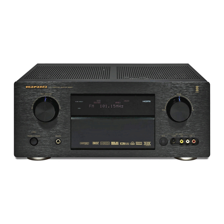
Page 9: Front Panel
HEADPHONE jack for stereo headphones Press this button to activate the Multiroom system. This jack may be used to listen to the SR7001’s “MULTI” indicator will be illuminated in the display. output through a pair of headphones. Be certain (See page 56) that the headphones have a standard 1/4”... -
Page 10: Fl Display And Indicater
¡9 ¡8 R SR DISP (Display Off) indicator C 6.1 This indicator is illuminated when the SR7001 is in ITAL DIGI the display off condition. SLEEP timer indicator 1 INP This indicator is illuminated when the sleep timer function in the main-room is in use. -
Page 11: Rear Panel
UNSWITCHED outlets are provided. A/B, Video) The one marked SWITCHED provides power only when the SR7001 is turned on and is useful for components which you use every time you play your system. The one marked UNSWITCHED is always live as long as the SR7001 is plugged into a live outlet. -
Page 12: Remote Controller Rc8001Sr
Learning Remote Controller • Set the AMP mode to use this button with the SR7001. MUTE button This button is used to mute the audio for the SR7001 and television. Note: • Set the AMP mode to use this button with the SR7001. -
Page 13: Lcd Indicators
Note: • Select the AMP as the source to use this remote controll with the SR7001. • The MD button does not work with the SR7001. ⁄5 LIGHT 1 and 2 buttons Pressing these buttons will light up the LCD and its buttons. -
Page 14: Remote Control Range
Close the cover until it clicks. The distance between the transmitter of the remote control and the IR SENSOR of the SR7001 should be less than 5 meters. If the remote control is pointed in a direction other than the IR SENSOR or if there is an obstacle between them, use of the remote control may not be possible. -
Page 15: Checking The Time
GENERAL INFORMATION OF RC8001SR TO SR7001 To control the SR7001 by your RC8001SR, you have to select the device AMP or TUNER by pressing the function selector button. Please refer below for the details in AMP and TUNER mode. -
Page 16: Connections
Surround left and right speakers CONNECTIONS When the SR7001 is used in surround operation, the preferred location for surround speakers is on the side walls of the room, at or slightly behind the SPEAKER PLACEMENT listening position. The center of the speaker should face into the The ideal surround speaker system for this unit is 7- room. -
Page 17: Connecting A Subwoofer
Dolby Digital RF output jack of the videodisc player to the digital input jack. • The digital signal jacks on the SR7001 conform to the EIA standard. If you use a cable that does not conform to this standard, the SR7001 may not function properly. -
Page 18: Connecting Hdmi Devices
HDMI signal may be affected by noise. An HDMI cable (sold separately) is used to connect the HDMI jack on the SR7001 with the HDMI jack on a DVD player, TV, projector or other component. To transmit multichannel audio via HDMI, the connected player must support multichannel audio transmission through its HDMI jack. -
Page 19: Connecting Video Components
MULTI OUT video signals properly. 7.1CH • If you connect the S-VIDEO or component signal to the S-VIDEO or component jack on the SR7001, it is AUDIO (AUX2) not necessary to connect the conventional video signal to the VIDEO (composite) jack. If you use both video... -
Page 20: Advanced Connecting
CONTROL EXTERNAL INTERNAL Whenever external infrared sensors or similar devices are connected to RC-5 IN of the SR7001, be sure to always disable operation of the infrared sensor on the main unit by using the following procedure. Hold down the MULTI button and the MENU button on the front panel at the same time for fi... -
Page 21: Connecting The Antenna Terminals
CONNECTING THE ANTENNA TERMINALS FM Antenna FM External Antenna INPUT 1(TV) INPUT 2(DVD) FM (75Ω) FM ( ( 75 75Ω Ω ) ) ANTENNA ANTENNA ANTENNA COMPONENT VIDEO INPUT 3(VCR1) INPUT 4(DSS/VCR2) INPUT 1(TV) INPUT 2(DVD) INPUT 3(VCR1) INPUT 4(DSS/VCR2) OUTPUT 1 OUTPUT 2 HDMI... -
Page 22: Xm Radio Overview
XM RADIO OVERVIEW SR7001 is the XM Ready ® receiver. You can receive XM Satellite Radio and-Play or Passport system (sold separately) and subscribing the XM service. Introducing XM Satellite Radio There’s a world of audio listening pleasure beyond AM and FM. XM Satellite Radio which includes: •... -
Page 23: Connecting For The Multi Room
CONNECTING FOR THE MULTI ROOM INPUT 1(TV) INPUT 2(DVD) ANTENNA FM (75Ω) COMPONENT VIDEO INPUT 3(VCR1) INPUT 4(DSS/VCR2) INPUT 1(TV) INPUT 2(DVD) INPUT 3(VCR1) INPUT 4(DSS/VCR2) OUTPUT 1 OUTPUT 2 HDMI Ver1.2 TV(1) DVD(2) VCR1(3) DSS/VCR2(4) MONITOR MULTI MULTI TV(1) DVD(2) VCR1(3) DSS/VCR2(4) -
Page 24: Connecting Other Equipment
IR receiver, by connecting an external IR receiver. s DC OUT (DC TRIGGER) External devices can be controlled from the SR7001 by connecting them to the DC OUT terminal (12 V). d EMITTER OUT (SR8001 Only) Outputs the remote control signal input to the IR An IR receiver is connected as shown above. -
Page 25: Setup
After all components are connected, initial setup must be performed. ONSCREEN DISPLAY MENU SYSTEM The SR7001 incorporates an onscreen menu system, which makes various operations possible by using the cursor (3, 4, 1 , 2) and OK/ENTER buttons on the remote control unit or on the front panel. - Page 26 E X I T R E T U R N “4. VIDEO SETUP” (P. 35) Note: • The SR7001 does not have the “HDMI OUT” and “COMPO OUT 2” sub-menus. MAIN MENU M A I N M E N U...
-
Page 27: Input Setup
1 INPUT SETUP This menu is for setting the matching the output of connected audio devices and the input jacks of this receiver. • FUNC INPUT SETUP : “1-1 FUNC INPUT SETUP” (see page 25) • 7.1 CH INPUT SETUP : “1-2 7.1 CH INPUT SETUP”... - Page 28 HDMI and COMPONENT inputs can be assigned to HDMI AUDIO of “5. PREFERENCE” is set to the preferred source. THROUGH, audio is not output from the SR7001. Use this menu to select which digital input jacks are (See page 36) to be assigned to which input source.
-
Page 29: Function Rename
1-3 FUNCTION RENAME Input sources can be registered under any name. This menu is for renaming input source. BACK: This menu is for renaming function name. Names can be up to 10 characters long, including spaces. (Characters are selected from those appearing on DEFAULT: the display.) This name appears on the receiver's FL display and the OSD, but it does not appear in the... -
Page 30: Spkr (Speaker) Setup
2 SPKR (SPEAKER) SETUP After you have installed the SR7001 connected all the components and determined the speaker layout, it is now time to perform the settings in the Speaker Setup menu for the optimum sound acoustics for your environment and speaker layout. - Page 31 SR7001 during this time. • During measurement, step away from the microphone and operate the SR7001 via the remote control unit from a position that is out of the path of the speaker When the detection check ends, the following sound.
- Page 32 A U T O A U T O Note: Do not turn the power to the SR7001 off while storing parameters in memory. This may erase all data in the SR7001’s memory and may damage the receiver. L E V E L 0 .
-
Page 33: Error Messages
ERROR MESSAGES Displayed Error MIC SET ERROR!! A U T O S E T U P A U T O S E T U P : S T A R T M A I N R O O M S U R R B A C K : 2 C H M I C... - Page 34 Note: This is important for the timing of the acoustics to create the proper sound space that the SR7001 and • If using small front speakers, set a slightly higher frequency. If using large front speakers, set a slightly today’s sound systems are able to produce.
-
Page 35: Test Mode
Press the OK/ENTER button to enter the selection. Move the cursor to FRONT L by pressing the 4 cursor button. The SR7001 will emit a pink noise from the front left speaker. Remember the level of this noise and then Advanced Speaker Array (ASA) press the 4 cursor button. -
Page 36: Surround Setup
3 SURROUND SETUP This menu is for setting surround effect parameters for the various surround input signals so as to bring out the live audio effect of your speaker system. • CHANNEL LEVEL: “3-1 CHANNEL LEVEL” (see page 33) • PLIIx MUSIC PARAMETER: “3-2 PLIIx MUSIC PARAMETER”... - Page 37 • If “NONE” was selected for the subwoofer speaker such as CDs. setting in the SPEAKER SIZE, then this setting will In this mode, the SR7001 includes three controls to not appear. fi ne-tune the sound fi eld as follows.
-
Page 38: Video Setup
HDMI 1 or HDMI 2, to output the signal to. Select the output destination with the 1 / 2 cursor buttons. 4-1 VIDEO CONVERT The SR7001 is equipped to convert video signals for monitor output. This section explains how to set up conversion for each type of video input. -
Page 39: Preference
2 cursor buttons. HDMI AUDIO: This setting determines whether to play back audio input to the HDMI jacks through the SR7001 or output it through the receiver to a TV or projector. ENABLE: The audio input to the HDMI jacks can be played back by this receiver. - Page 40 MSPK (MULTI SPEAKER): A only) for the two other rooms in the multi room Switch the speaker output “ON” or “OFF” with the system. (The SR7001 has only one other room in the 1 or 2 cursor buttons. multi-room system.) VOL (VOLUME SETUP): These features can be set from this menu.
-
Page 41: Acoustic Eq
6 ACOUSTIC EQ This display is for setting up the equalizer and changing the Equalizer mode. After you complete this portion of the setup, move the • PRESET G. EQ ADJ : cursor to “RETURN” with the 3, 4, 1 and 2 cursor “6-1 PRESET G. - Page 42 6-1 PRESET G. EQ ADJ 6-2 CHECK AUTO These modes allow you to set a 9-band graphic These menus are for confirming the results of equalizer for each of the 7 channels. AUTO SETUP function equalizer measurement (AUDYSSEY, FRONT, FLAT). Select “6.
-
Page 43: Basic Operation (Play Back)
“18 dB - Maximum value of channel level) NIGHT MODE page 42. press either the THX button on the SR7001 or the THX button on the remote control unit. individual surround mode button on page 1.2 on the remote control unit. -
Page 44: Video Convert
S-VIDEO MONITOR OUT terminals. OSD information is also output when the video conversion feature is on and the video signal input to the VIDEO or S-VIDEO input jack of the SR7001 AV SURROUND RECEIVER SR8001 is converted and output from the COMPONENT... -
Page 45: Surround Mode
AUTO SURROUND MODE When this mode is selected, the SR7001/SR8001 determines whether the digital input signal is Dolby SURROUND Digital, Dolby Digital Surround EX, DTS, DTS-ES, DTS 96/24 or PCM audio. The SR7001/SR8001 is equipped with many Surround EX & DTS-ES will operate for multichannel surround modes. - Page 46 In stereo program sources, the left and right channels signals from certain CD players if you connect play normally when PCM audio or analog stereo is the player to the SR7001/SR8001 digitally. This input. is because the digital signal has been processed With Dolby Digital and DTS sources, the 5.1 channels...
- Page 47 The surround mode is selected with the surround AUTO mode selector on the SR7001 or the remote control unit. However, the sound you hear is subject to the relationship between the selected surround mode and the input signal. That relationship is as follows:...
- Page 48 Surround Mode Input Signal Decoding Dolby Virtual Dolby Surr.EX Dolby Virtual Speaker Dolby D (5.1ch) Dolby Virtual Speaker Speaker Dolby D (2ch) Dolby Virtual Speaker Dolby D (2ch Surr) Dolby Virtual Speaker DTS-ES Dolby Virtual Speaker DTS 96/24 Dolby Virtual Speaker DTS (5.1ch) Dolby Virtual Speaker Multi Ch-PCM...
-
Page 49: Other Function
LISTENING THROUGH HEADPHONES In the above situation, turn the TV TUNER OFF This jack may be used to listen to the SR7001’s or select a channel that does not contain any output through a pair of headphones. Be certain that broadcast. -
Page 50: Display Mode
SETUP” from the MAIN MENU. (See page 25) RECORDING AN ANALOG SOURCE In normal operation, the audio or video source selected for listening through the SR7001 is sent to the record outputs. This means that any program you are watching... -
Page 51: Speaker A/B
VOL buttons on the remote. LIP.SYNC Depending on the image device (TV, monitor, projector, etc.) connected to the SR7001, a time lag can occur between image signal processing and audio signal processing. Though minor, this time lag can interfere with movie and music enjoyment. -
Page 52: Basic Operation (Tuner)
(Using the SR7001) BASIC OPERATION Turn the INPUT SELECTOR knob to select (TUNER) “TUNER”. Press the BAND button to select either FM or To operate the unit from the remote control, press the TUNER button on the remote control so that the Press the 3 or 4 cursor buttons on the front tuner mode is engaged. -
Page 53: Auto Preset Memory
MODE This function automatically scans the FM and AM PURE DIRECT band and enters all stations with proper signal strength into the memory. 2. 4. 1. 3. (Using the SR7001) AV SURROUND RECEIVER SR8001 READY INPUT SELECTOR VOLUME PURE DIRECT... - Page 54 CLEARING STORED PRESET STATIONS SORTING PRESET STATIONS You can remove preset stations from the memory using the following procedure. INPUT SELECTOR TEST CH.SEL SURR 7.1CH SPK-AB VOLUM STANDBY POWER ON/STANDBY DISP SLEEP SPKR A B V-OFF PEAK ANALOG SURROUND DISC 6.1 MTX 6.1 NIGHT DIGITAL...
-
Page 55: Listening To Xm Satellite Radio
LISTENING TO XM SATELLITE RADIO AND RADIO ID SELECTING AN INPUT SOURCE Before you can listen to XM Satellite Radio, you must fi rst select the input source on the SR7001. AV SURROUND RECEIVER SR8001 PAGE INPUT SELECTOR PURE DIRECT... -
Page 56: Preset Search Mode
C A T : R o c k Note: • To change the display content from XM information to SR7001 functions, do so from the display mode. (See “DISPLAY MODE” on page 47) When this display appears, press the OSD button again. -
Page 57: Preset Memory
AUX2 LIGHT RC8500SR Learning Remote Controller (Using the SR7001) Press the ENTER button on the front panel. Press the 1 or 2 button on the front panel to select the desired Category. After selecting the Category, Press the 3 or 4 cursor button to select the desired station of the category. - Page 58 PRESET SCAN CLEARING STORED PRESET STATIONS You can remove preset stations from the memory using the following procedure. 3.5. PAGE SPKR A B V-OFF PEAK ANALOG DISC 6.1 MTX 6.1 NIGHT DIGITAL BAND T-MODE DISPLAY TUNER TUNER CD-R LIP.SYNC PREV MUTE ENTER EXIT...
-
Page 59: Multi Room System
MULTI OUT A and B AUDIO output terminals to the MULTI ROOM A and B amps. Note: • The SR7001 does not have a MULTI ROOM B setting. Connect the VIDEO output (MULTI OUT) terminal to the monitor in Room A. -
Page 60: Operation Of The Multi Room Outputs With
(Room B output cannot be operated from another until PAGE 4 is displayed. Press the MULTI room.) (D1) button.) This operations will put the SR7001 into multi room mode and “MULTI” will be illuminated on the display. MULTl ROOM Video out put will show OSD information for the MULTI ROOM setup. -
Page 61: Remote Controller Operation
Press the desired operation buttons to play the selected component. • For details, refer to the component’s user guide. • It may not be possible to operate some models. CONTROLLING A MARANTZ DVD PLAYER (DVD MODE) SOURCE ON/OFF Turns the DVD player on and off POWER ON... - Page 62 CONTROLLING A MARANTZ CD RECORDER (CDR MODE) SOURCE ON/OFF Turns the CD recorder on and off POWER ON Turns the CD recorder on POWER POWER ON/OFF ON/OFF POWER OFF Turns the CD recorder off SOURCE SOURCE D1 - D5 / >(Page) (Refer to page vi)
-
Page 63: Basic Operation
DVD. Pressing the SOURCE button once changes the remote control to the settings for the source that • When using Marantz products, TV and DVD can was pressed. To change the amplifi er or other source, press the SOURCE button twice (double-click). -
Page 64: Learn Mode
For codes which are not learned, the remote control Follow the same procedure to make the remote will transmit either the Marantz preset codes from control learn the other buttons. the initial settings, or remote codes from another Repeat the procedure in steps 3 to 6 to have manufacturer’s AV equipment which is set by the... -
Page 65: Erasing Programmed Codes
ERASING PROGRAMMED CODES Press the DVD source button . (RETURNING TO INITIAL SETTINGS) indicator blinks. NAME The “ ” blinks to indicate that the letter can be Codes can be erased in fi ve ways: by buttons, direct changed. buttons, direct button pages, sources, and by all Press the 2 cursor button twice. -
Page 66: Programming Macros
Erasing All Note: • If the signal transmission interval (interval time) This procedure clears (resets) all programmed is changed using the Setup mode (described later), codes and names. Once all the data is cleared, the this transmission interval is applied to all macro memory is returned to the factory default status. - Page 67 Press the D4 (MACRO) direct button. The macro menu is displayed. MACRO indicator displays and LEARN blinks. Press the D1 (M-01) direct button . The NAME is displayed. Press the D3 (NAME) direct button . The “ ” blinks to indicate that rewriting is possible. Press the 5 numeric button to select M.
-
Page 68: Clone Mode
SETTING THE MACRO TIMER EXECUTING THE MACRO TIMER Setting the macro timer enables the macro program The macro program starts when the time that was to automatically turn the power for a device on or off set is reached. The TIMER or perform other operations. -
Page 69: Setup
• If the copying fails in the middle of the copying process, ERROR is displayed on the remote control. Check and perform steps 1 to 7 again. Once copying is completed, press the M button on both remote controls. SETTING THE MACRO INTERVAL TIME When a macro program is executed, control signals are transmitted in sequence. -
Page 70: Troubleshooting
If your trouble cannot be recovered with the remedy actions listed in the following table, malfunction of the internal circuitry is suspected; immediately unplug the power cable and contact your dealer, nearest Marantz authorized dealer or the Marantz Service Center in your country. -
Page 71: Hdmi
A 5 m or shorter cable is recommended to ensure stable operation and prevent image quality deterioration. Turn on the power to the SR7001/ SR8001. Shut off and then turn the power back on to the SR7001/SR8001, TV and source component. -
Page 72: Technical Specifications
Should the operation or display seem to be abnormal, reset the unit with the following procedure. SR8001 The SR7001 is turned on, press and hold the MULTI Power Output (20 Hz – 20 kHz/THD=0.08%) Front L&R ...8 ohms 125 W / Ch + SPEAKERS A/B buttons simultaneously for 3 Center ...8 ohms 125 W / Ch... -
Page 73: Setup Codes
Source button name : AMP Integra Brand name Setup code Amstrad 0105 Arcam 0296 Audiolab 0296 Kenwood Carver 0296 0105 Magnavox Genexxa 0422 Marantz Grundig 0296 Micromega Harman/Kardon 0919 Musicmagic 0358 Myryad Left Coast 0919 Linn 0296 Norcent Magnavox 0296 Onkyo... - Page 74 1032 Carver Orbitech 1127 Grundig Pace 0482, 0874, 1202, 1350 Harman/Kardon Panasonic 0274, 0728, 0874, 1347 Magnavox Panda 0482 Marantz Paysat 0751 Myryad Philips 1169, 0776, 1776, 0751, 1103, 0749, 0160, 0227, Optimus 0482, 0880 Philips Pioneer 0880 Pioneer Promax...
- Page 75 Source button name : TV Source button name : TV Brand name Setup code Brand name Chun Yun 0027, 0207, 0036, 0119 Chung Hsin 0207, 0080, 0135 Cimline 0036 Cineral 0478, 0119 Gateway Citizen 0087, 0057, 0119 Geloso Clarion 0207 Genexxa Clarivox 0064...
- Page 76 Loewe 0064, 0108, 1589 Logik 0267, 0099 Luxor 0075, 0131, 0070 M Electronic 0027 0062 0267, 0070 MGN Technology 0267 0267, 0027 Magnasonic 1305 Magnavox 0062, 0066, 0108, 0027, 1808 Magnin 0267 Manesth 0072, 0099 Marantz 0062, 0108 Marta 0064...
- Page 77 Zenith 0066, 0060, 0027, 1506 0072 0075, 0834 0131, 0099 0267 Source button name : DVD 0064, 0108, 0131 Brand name Setup code 0064 MARANTZ DVD1 0001 0072, 0099 MARANTZ DVD2 0002 0108 Acoustic Solutions 0757 0641, 0643 Alba 0744...
-
Page 78: Direct Button Functions
Source button name : DVD DIRECT BUTTON PAGE PAGE 1 FUNCTIONS Source button name : AMP PAGE Command Note PAGE 1 1 AUTO SELECT AUTO SURROUND PAGE 2 SELECT DOLBY MODE 3 DTS SELECT DTS MODE 4 EX/ES SELECT EX/ES 5 DIRECT SELECT PURE DIRECT PAGE 2... - Page 79 You can find your nearest authorized distributor or dealer on our website. is a registered trademark. Printed in China 06/2006 00M05CW851250 ecmf-d...
Need help?
Do you have a question about the SR7001 and is the answer not in the manual?
Questions and answers