Table of Contents
Advertisement
Advertisement
Table of Contents

Related Manuals for SOYO SY-K7V DRAGON Plus!


Summary of Contents for SOYO SY-K7V DRAGON Plus!
- Page 1 SY-K7V DRAGON Plus! Motherboard **************************************************** K7 Ath1on & Duron Processor supported VIA KT266A AGP/PCI Motherboard 100/133 MHz Front Side Bus supported ATX Form Factor **************************************************** User's Manual...
- Page 2 It is the policy of SOYO Computer Inc. to respect the valid patent rights of third parties and not to infringe upon or to cause others to infringe upon such rights.
-
Page 3: Table Of Contents
SY -K7V DRAGON PLUS! MOTHERBOARD COMPONENTS ..8 CHAPTER 2 HARDWARE INSTALLATION ........10 PREPARATIONS............10 INSTALLATION GUIDE ..........11 QUICK BIOS SETUP.............36 CHAPTER 3 BIOS SETUP UTILITY..........38 SOYO COMBO SETUP ..........41 STANDARD CMOS SETUP..........45 ADVANCED BIOS FEATURES ........49 ADVANCED CHIPSET FEATURES ......53 INTEGRATED PERIPHERALS........60 POWER MANAGEMENT SETUP ........66 PNP/PCI CONFIGURATIONS........72... - Page 4 Table of Contents SY-K7V DRAGON Plus! CHAPTER 7 ..91 PROMISE RAID FAMILY DRIVER INSTALLATION CHAPTER 8 ULTRA FAMILY DRIVER INSTALLATION ...93 APPENDIX A FASTTRAK-100-LITE MANUAL ......95 APPENDIX B ...156 C-MEDIA 6 CHANNEL AUDIO SOLUTION MANUAL APPENDIX C TROUBLESHOOTING AT FIRST START .....184 APPENDIX D ...........191 CONTACT INFORMATION...
-
Page 5: Chapter 1 Motherboard Description
1-2 UNPACKING THE MOTHERBOARD When unpacking the Motherboard, check for the following items: The SY-K7V DRAGON Plus! KT266A AGP/PCI Motherboard The user manual The Installation CD-ROM SOYO Bonus Pack CD-ROM 3 IDE Device ATA 66 Flat Cable One Floppy Disk Drive Flat Cable... -
Page 6: Key Features
SY-K7V DRAGON Plus! as well. CPU SETTINGS The SY-K7V DRAGON Plus! provides the user with a very complete and convenient CPU setting environment. The CPU settings are all adjusted through the special SOYO COMBO page in the BIOS, therefore rendering... - Page 7 Motherboard Description SY-K7V DRAGON Plus! the use of jumpers obsolete. CPU FSB Frequency The SY-K7V DRAGON Plus! supports a wide range of CPU FSB frequency settings: (CPU FSB Frequency can be setup by 1MHz increment) 100~132MHz for 100MHz FSB CPU 133~233MHz for 133MHz FSB CPU This ensures that the SY-K7V DRAGON Plus! has an overwhelming overclocking potential.
-
Page 8: Hardware Monitor
Motherboard Description SY-K7V DRAGON Plus! C-MEDIA HARDWARE AUDIO Supports 4/5/5.1 speakers and DLS based wave table music. Also provides professional SPDIF IN/OUT non-distortion digital interface. LAN ON-BOARD Supports 10/100 Mbps base-T Ethernet. SMART CARD READER Compliant with Personal Computer Smart Card(PC/SC) Working Group standard. -
Page 9: Handling The Motherboard
This green LED gives an indication of the presence of the 5V Standby voltage. This voltage is always fed into the motherboard and is used for functions such as WOL. SOYO Bonus Pack CD-ROM COMPLIANCE The SY-K7V DRAGON Plus! complies with all important industry standards. -
Page 10: Electrostatic Discharge Precautions
Motherboard Description SY-K7V DRAGON Plus! Warning: Do not apply power if the Motherboard appears damaged. If there is damage to the board, contact your dealer immediately. 1-5 ELECTROSTATIC DISCHARGE PRECAUTIONS Make sure to ground yourself before handling the Motherboard or other system components. -
Page 11: Sy-K7V Dragon Plus! Motherboard Layout
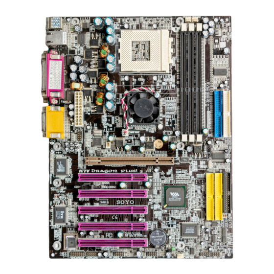
Motherboard Description SY-K7V DRAGON Plus! 1-6 SY-K7V DRAGON Plus! MOTHERBOARD LAYOUT PS/2 KB PS/2 Mouse Connector Connector USB 1_2 COM 1 ATX Power COM 2 SDRAM KT266A LINE-OUT SDRAM LINE-IN IDE 1 IDE 2 GAME PORT AGP PRO Audio PCI Slot #1 FDC1 CD_SPDIF CDIN2... -
Page 12: Sy-K7V Dragon Plus! Motherboard Components
Motherboard Description SY-K7V DRAGON Plus! 1-7 SY-K7V DRAGON Plus! MOTHERBOARD COMPONENTS SDRAM SDRAM □... - Page 13 Motherboard Description SY-K7V DRAGON Plus! ATX Power Supply Connector VIA KT266A North Bridge Chip Socket A Connector CPU Cooling Fan Connector Bus Mastering EIDE/ATAPI Ports DDR DIMM Banks Chassis Cooling Fan Connector AGP Pro Slot 32-bit PCI Mastering Slots VIA VT8233CE South Bridge Chip Floppy Disk Drive (FDD) Port IDE RAID Ports IDE RAID Jumper...
-
Page 14: Chapter 2 Hardware Installation
Hardware Installation SY-K7V DRAGON Plus! Chapter 2 HARDWARE INSTALLATION Congratulations on your purchase of SY-K7V DRAGON Plus! Motherboard. You are about to install and connect your new Motherboard. Note: Do not unpack the Motherboard from its protective anti-static packaging until you have made the following preparations. -
Page 15: Installation Guide
Hardware Installation SY-K7V DRAGON Plus! 2-2 INSTALLATION GUIDE We will now begin the installation of the Motherboard. Please follow the step-by-step procedure designed to lead you to a complete and correct installation. Step 1- Install the Central Processing Unit (CPU) Step 2- Install memory modules Step 3- Install expansion cards Step 4- Connect cables, case wires, and power supply... -
Page 16: Step 1 Install The Cpu
Hardware Installation SY-K7V DRAGON Plus! Step 1 Install the CPU Mark your CPU Frequency: Record the working frequency of your CPU that should be clearly marked on the CPU cover. 200MHz FSB DDR transfer on Athlon 750 MHz (100x7.5) 800 MHz (100x8.0) 850 MHz (100x8.5) 900 MHz (100x9.0) 950 MHz (100x9.5) -
Page 17: Cpu Fan Installation
Hardware Installation SY-K7V DRAGON Plus! Seat the processor in the socket completely and without forcing. Then close the socket handle to secure the CPU in place. Remember to connect the CPU Cooling Fan to the appropriate power connector on the Motherboard. The fan is a key component that will ensure system stability. - Page 18 Hardware Installation SY-K7V DRAGON Plus! CPU Fan Mount Procedure: To prevent scratch or damage on the motherboard, please follow these instruction on how to mount the CPU fan properly. 1. Apply thermal paste to the die of the CPU. 2. Carefully mount the fan on top of the CPU and clip-on the first lock. 3.
- Page 19 FOC function. FOC ( Fan-Off Control ) The newly designed SOYO “FOC” is based on the concept of total protection for CPU, which is very different from currently seen on the market. The H/W control function is used to see a passive security system of monitoring and warning.
- Page 20 Hardware Installation SY-K7V DRAGON Plus! “FOC” includes the following functions: (1) Simultaneous Signal Follow Ups: Before the system enters the O/S, H/W will detect the signals of the CPU fan pins, get their revolution information and send it to the BIOS. (2) Auto Power Off System: If the BIOS gets the information of CPU fan revolution, it goes on working normally.
-
Page 21: Step 2 Install Memory Module
Hardware Installation SY-K7V DRAGON Plus! Step 2 Install Memory Module SDRAM SDRAM □ Your board comes with three DIMM sockets, providing support for up to 3GB of main memory using unbuffered and non-ECC DIMM modules from 64MB to 1GB. On this motherboard, DRAM speed can be set independent from the CPU front side bus speed. -
Page 22: Memory Configuration Table
Hardware Installation SY-K7V DRAGON Plus! Memory Configuration Table Number of Memory DIMM 1 DIMM 2 DIMM 3 Modules RAM Type DDR RAM Memory Module Size 64 / 128 / 256 / 512 / 1024 MB (MB) Step 3 Install Expansion Card The motherboard has 1 AGP PRO slot and 5 PCI slot. - Page 23 Hardware Installation SY-K7V DRAGON Plus! Step 4 Connect cables, case wires, and power supply A. IDE Device Installation (HDD, CD-ROM) SDRAM Pin -1 IDE 1 IDE 2 SDRAM Primary Secondary □ Pin -1 IDE 3 IDE 4 This Motherboard offers two primary and secondary IDE device connectors (IDE1, IDE2).
- Page 24 Hardware Installation SY-K7V DRAGON Plus! 80-Conductor ATA 66/100 Flat Cable 40-pin...
-
Page 25: Floppy Drive
Hardware Installation SY-K7V DRAGON Plus! B. Floppy Drive Installation SDRAM SDRAM Pin -1 □ Floppy Drive Connector The system supports 5 possible floppy drive types: 720 KB, 1.2 MB, 1.44 MB, 2.88 MB, and LS-120. Connect one side of the 34-pin flat cable to the floppy drive and plug the other end to the floppy drive connector on the Motherboard. -
Page 26: Power Led
Hardware Installation SY-K7V DRAGON Plus! Front Panel Connections Speaker Power LED SDRAM SDRAM Reset PWRBT HDD LED □ Plug the computer case's front panel devices to the corresponding headers on the Motherboard. 1. Power LED Please install according to the following pin assignment: pin 1,3 are for Power LED. - Page 27 Hardware Installation SY-K7V DRAGON Plus! 2. Reset Plug the Reset push-button cable into the 2-pin Reset header on the Motherboard. Pushing the Reset button on the front panel will cause the system to restart the boot-up sequence. Reset Pin Assignment Power Good 3.
- Page 28 Hardware Installation SY-K7V DRAGON Plus! 5. ATX Power On/Off Switch Attach the 2-pin momentary type switch to the PWRBT header for turning On or Off your ATX power supply. PWRBT Pin Assignment Power On/Off D. Back Panel Connections All external devices such as the PS/2 keyboard, PS/2 mouse, printer, modem, USB can be plugged directly onto the Motherboard back panel.
- Page 29 Hardware Installation SY-K7V DRAGON Plus! 1. Onboard Serial Ports COM1/COM2 External peripherals that use serial transmission scheme include: serial mouse, and modem. Plug the serial device cables directly into the COM1/COM2 9-pin male connectors located at the rear panel of the Motherboard. 2.
- Page 30 Hardware Installation SY-K7V DRAGON Plus! 5. Universal Serial Bus USB1/USB2 (USB3/USB4;USB5/USB6) This Motherboard provides four USB ports for your additional devices. Plug the USB device jack into the available USB connector USB1 or USB2. Standard device drivers come with the Win98 for commonly used USB devices.
- Page 31 Hardware Installation SY-K7V DRAGON Plus! 6. Onboard Game port/audio This Motherboard provides Joystick port and audio. Attach the joystick cable to the 15-pin GAME port at the rear panel of you motherboard. This Motherboard features three built-in audio-stereo ports (labeled line-in, line-out, and mic jack) convenient to directly plug-in all your external audio devices.
- Page 32 Hardware Installation SY-K7V DRAGON Plus! 2. Standard Infrared (SIRCON) Plug the 10-pin infrared device cable to the SIRCON header. This will enable the infrared transfer function. This Motherboard meets both the ASKIR and HPSIR specifications. Please install according to the following pin assignment: Standard Infrared (SIRCON) Connector SIRCON Pin Assignment...
- Page 33 Hardware Installation SY-K7V DRAGON Plus! 3. Cooling Fan Installation (1) CPU Cooling Fan (CPUFAN1,CPUFAN2) After you have seated the CPU properly on the processor, attach the 3-pin fan cable to the CPUFAN connector on the Motherboard. The fan will stop when the system enters into Suspend Mode.
- Page 34 Hardware Installation SY-K7V DRAGON Plus! (2) Chassis Cooling Fan (CHAFAN1,CHAFAN2,CHAFAN3) Some chassis also feature a cooling fan. This Motherboard features a CHAFAN connector to provide 12V power to the chassis fan. Connect the cable from the chassis fan to the CHAFAN 3-pin connector. Install according to the following pin assignment: Chassis Cooling Fan (CHAFAN1,CHAFAN2,CHAFAN3)
- Page 35 Hardware Installation SY-K7V DRAGON Plus! 4. CD Line-in (CDIN1,CDIN2) This Motherboard provides two CD-Line in connectors. Please connect the 4-pin audio cable from your CD-ROM drive to either CDIN1 or CDIN2. (It fits in only one, depending on the cable that came with your CD-ROM drive) Please install according to the following pin assignment: CDIN1,CDIN2(CD Line-in)
- Page 36 Hardware Installation SY-K7V DRAGON Plus! 6. SPK5 Please refer to the c-media 6 channel Audio solution Manual for more information on AUDIO function. CENTER/BASS REAR_L/R OPTICAL_INPUT SPDIF_INPUT OPTICAL_OUTPUT SPDIF_OUTPUT 7. CD_SPDIF CD_SPDIF SPDIF IN2...
-
Page 37: Atx Power
Hardware Installation SY-K7V DRAGON Plus! F. ATX Power Supply Plug the connector from the power directly into the 20-pin male ATX PW connector on the Motherboard, as shown in the following figure. ATX Power SDRAM SDRAM □ Warning: Follow these precautions to preserve your Motherboard from any remnant currents when connecting to ATX power supply: Turn off the power supply and unplug the power cord of the... - Page 38 Hardware Installation SY-K7V DRAGON Plus! ATX Power 5VSB PW-OK Pay special care to the directionality. PS-ON 3.3V -12V 3.3V 3.3V G. Jumper Setting RAID_IDE(IDE3,4) Function Selector Short pin 1-2 enables RAID function on IDE 3,4 port. Short pin 2-3 enables regular IDE, RAID function is disabled. IDE 3,4 will function as normal IDE port (need to install Ultra Family Driver), please see Chapter 8.
-
Page 39: Step 5 Power On
Hardware Installation SY-K7V DRAGON Plus! H. CMOS Clear (JP5) In some cases the CMOS memory may contain wrong data, follow the steps below to clear the CMOS memory. Clear the CMOS memory by momentarily shorting pin 2-3 on jumper JP5. This jumper can be easily identified by its white colored cap. Then put the jumper back to 1-2 to allow writing of new data into the CMOS memory. -
Page 40: Quick Bios Setup
This Motherboard does not use any hardware jumpers to set the CPU frequency. Instead, CPU settings are software configurable with the BIOS [SOYO COMBO FEATURE]. The [SOYO COMBO FEATURE] combines the main parameters that you need to configure, all in one menu, for a quick setup in BIOS. - Page 41 Select the “LOAD OPTIMIZED DEFAULTS” menu and type “Y” at the prompt to load the BIOS optimal setup. Step 3. Select [SOYO COMBO FEATURE] Set the [CPU Frequency Select] to 100/133MHz, depending on the Front Side Bus of your CPU.
-
Page 42: Chapter 3 Bios Setup Utility
2. After the diagnostic checks, press the [Del] key to enter the Award BIOS Setup Utility. CMOS Setup Utility – Copyright ( C ) 1984-2001 Award Software SOYO COMBO Feature PC Health Status Standard CMOS Features Load Fail - Safe Defaults... - Page 43 BIOS Setup Utility SY-K7V DRAGON Plus! Hot Keys: Function keys give you access to a group of commands throughout the BIOS utility. Function Command Description Gives the list of options available for each General Help item. Previous Restore the old values. These are the values Values that the user started the current session with.
-
Page 44: Bios Setup Utility
BIOS Setup Utility SY-K7V DRAGON Plus! SAVE AND EXIT SETUP Select the [SAVE & EXIT SETUP] option from the Main Menu to save data to CMOS and exit the setup utility. This option saves all your changes and causes the system to reboot. R O M P C I / I S A B I O S... -
Page 45: Soyo Combo Setup
<DEL> key during the system diagnostic checks to enter the Award BIOS Setup program. The CMOS SETUP UTILITY will display on screen. Then, select the [SOYO COMBO SETUP] option from the main menu and press the <Enter> key. -
Page 46: Soyo Combo Feature
Setting Description Note System Normal Adjust your computer Default performance. Performance Turbo SOYO COMBO Feature Setting Description Note Auto Detect Disabled When enabled, this item will auto detect if the DIMM and DIMM/PCI Clk Enabled Default PCI socket have devices and will send clock signal to DIMM and PCI devices. -
Page 47: System Boot Control Settings
BIOS Setup Utility SY-K7V DRAGON Plus! CPU Vcore Select Setting Description Note CPU Vcore Default +0.200V This function adjust Default Select the CPU voltage. +0.025V +0.225V +0.050V +0.250V +0.075V -0.025V +0.100V -0.050V +0.125V -0.075V +0.150V -0.100V +0.175V Quick Power On Self Test Setting Description Note... - Page 48 BIOS Setup Utility SY-K7V DRAGON Plus! C.I.H. 4-WAY Protection Settings Setting Description Note Disabled When set to enabled, the BIOS can only C.I.H. 4-WAY be programmed through AWDFLASH, Enabled Default Protection making sure that any virus is unable to program the system BIOS. Set to disable the BIOS can be programmed the traditional way.
-
Page 49: Standard Cmos Setup
BIOS Setup Utility SY-K7V DRAGON Plus! 3-2 STANDARD CMOS SETUP Select the [STANDARD CMOS SETUP] option from the Main Menu and press [Enter] key. CMOS Setup Utility – Copyright ( C ) 1984-2001 Award Software Standard CMOS Features Date (mm:dd:yy) Mon, Jan 1 2001 Item Help Time (hh:mm:ss) - Page 50 BIOS Setup Utility SY-K7V DRAGON Plus! This Main Menu function automatically detects the hard disk type and configures the [Standard CMOS Features] accordingly. CMOS Setup Utility – Copyright ( C ) 1984-2001 Award Software IDE Primary Master IDE HDD Auto-Detection Press Enter Item Help IDE Primary Master...
-
Page 51: Floppy Drives
BIOS Setup Utility SY-K7V DRAGON Plus! Hard Disks Type & Mode Choose the type and mode for the hard disks that you have already installed. Setting Description Note Press Enter To auto-detect the HDD’s size, IDE HDD head… on this channel Auto-Detection IDE Primary Auto... - Page 52 BIOS Setup Utility SY-K7V DRAGON Plus! Others Optional Setting Description Note EGA/VGA Select the video mode. Default Video CGA 40 CGA 80 MONO (Monochrome) ALL Errors When the BIOS detects system Default Halt On errors, this function will stop the No Errors system.
-
Page 53: Advanced Bios Features
BIOS Setup Utility SY-K7V DRAGON Plus! 3-3 ADVANCED BIOS FEATURES Select the [Advanced BIOS Features] option from the Main Menu and press [Enter] key. CMOS Setup Utility – Copyright ( C ) 1984-2001 Award Software Advanced BIOS Features Virus Warning Disabled Item Help CPU Internal Cache... -
Page 54: Boot Up Floppy Seek
BIOS Setup Utility SY-K7V DRAGON Plus! Cache Memory Options Setting Description Note Disabled CPU Internal Cache Enabled Enables the CPU's internal Default cache. External Cache Disabled Enabled Enables the external Default memory. Boot Up Floppy Seek Setting Description Note Disabled Seeks disk drives during boot up. -
Page 55: Security Option
BIOS Setup Utility SY-K7V DRAGON Plus! Typematic Settings Setting Description Note Disabled Keystrokes repeat at a rate Default Typematic Rate Setting determined by the keyboard. Enabled When enabled, the typematic rate and typematic delay can be selected. The following [Typematic Rate] and [Typematic Delay] fields are active only if [Typematic Rate Setting] is set to [Enabled] Typematic Rate 6 (Char/sec) - Page 56 ROM to RAM. BIOS shadow copies BIOS code from slower ROM to faster RAM. BIOS can then execute from RAM. LOGO-0 Allows user to display SOYO Default EPA LOGO SELECT logo or own logo. LOGO-1 Logo-0 Shows SOYO logo.
-
Page 57: Advanced Chipset Features
BIOS Setup Utility SY-K7V DRAGON Plus! 3-4 ADVANCED CHIPSET FEATURES Select the [Advanced Chipset Features] option from the Main Menu and press [Enter] key. Caution: Change these settings only if you are already familiar with the Chipset. The [Advanced Chipset Features] option changes the values of the chipset registers. -
Page 58: Chipset Features Setup
BIOS Setup Utility SY-K7V DRAGON Plus! CHIPSET FEATURES SETUP Setting Description Note Disabled Default Memory Hole 15M-16M Some interface cards will map their ROM address to this area. If this occurs, select [15M-16M] in this field. System BIOS Disabled Cacheable Enabled The ROM area F0000H-FFFFFH Default... - Page 59 BIOS Setup Utility SY-K7V DRAGON Plus! 3-4.1 DRAM Clock/Drive Control Caution: Change these settings only if you are already familiar with the Chipset. The [DRAM Clock/Drive Control] option changes the values of the chipset registers. These registers control the system options in the computer. CMOS Setup Utility –...
- Page 60 BIOS Setup Utility SY-K7V DRAGON Plus! DRAM Clock/Drive Control Setting Description Note DRAM Clock This item allows you to control the DRAM speed. By SPD Default DRAM Timing By SPD If enable the DRAM will auto detect the DRAM timing. Default Manual SDRAM Cycle...
-
Page 61: Agp & P2P Bridge Control
BIOS Setup Utility SY-K7V DRAGON Plus! 3-4.2 AGP & P2P Bridge Control Caution: Change these settings only if you are already familiar with the Chipset. The [AGP & P2P Bridge Control] option changes the values of the chipset registers. These registers control the system options in the computer. CMOS Setup Utility –... - Page 62 BIOS Setup Utility SY-K7V DRAGON Plus! AGP & P2P Bridge Control Setting Description Note AGP Aperture Select the size of Accelerated Graphics Default Port (AGP) aperture. The aperture is a Size 4M, 8M, portion of the PCI memory address 16M, 32M, range dedicated for graphics memory 128M, address space.
- Page 63 BIOS Setup Utility SY-K7V DRAGON Plus! 3-4.3 CPU & PCI Bus Control Caution: Change these settings only if you are already familiar with the Chipset. The [CPU & PCI Bus Control] option changes the values of the chipset registers. These registers control the system options in the computer. CMOS Setup Utility –...
-
Page 64: Integrated Peripherals
BIOS Setup Utility SY-K7V DRAGON Plus! 3-5 INTEGRATED PERIPHERALS Select the [Integrated Peripherals] option from the Main Menu and press [Enter] key. Caution: Change these settings only if you are already familiar with the Chipset. The [INTEGRATED PERIPHERALS] option changes the values of the chipset registers. - Page 65 BIOS Setup Utility SY-K7V DRAGON Plus! INTEGRATED PERIPHERALS (Continue) Setting Description Note OnChip USB All Disabled This should be enabled if Controller your system has a USB All Enabled installed on the system 1&2 USB Port board and you want to use 2&3 USB Port it.
-
Page 66: Via Onchip Ide Device
BIOS Setup Utility SY-K7V DRAGON Plus! 3-5.1 VIA OnChip IDE Device Caution: Change these settings only if you are already familiar with the Chipset. The [VIA OnChip IDE Device] option changes the values of the chipset registers. These registers control the system options in the computer. The following screen shows setup default settings. - Page 67 BIOS Setup Utility SY-K7V DRAGON Plus! VIA OnChip IDE Device Setting Description Note On-Chip PCI IDE Disabled Turn off the on-board Primary Secondary Enabled Use the on-board IDE Default mode 0-4 0 is the slowest speed Primary Master PIO 4 is the fastest speed Primary Slave PIO Auto For better performance...
-
Page 68: Superio Device
BIOS Setup Utility SY-K7V DRAGON Plus! 3-5.2 SuperIO Device Caution: Change these settings only if you are already familiar with the Chipset. The [SuperIO Device] option changes the values of the chipset registers. These registers control the system options in the computer. The following screen shows setup default settings. - Page 69 BIOS Setup Utility SY-K7V DRAGON Plus! SuperIO Device (Continue) Setting Description Note Onboard Disabled Serial Port 1 / 3F8/IRQ4 Choose serial port 1 & 2's I/O Default Serial Port 2 address. (port 1) Do not set port 1 & 2 to the same 2F8/IRQ3 Default address except for Disabled or...
-
Page 70: Power Management Setup
BIOS Setup Utility SY-K7V DRAGON Plus! 3-6 POWER MANAGEMENT SETUP The [POWER MANAGEMENT SETUP] sets the system's power saving functions. CMOS Setup Utility – Copyright ( C ) 1984-2001 Award Software Power Management Setup ACPI Suspend Type S1 (POS) Item Help Power Management Option User Define Menu Level... - Page 71 BIOS Setup Utility SY-K7V DRAGON Plus! Power Management Controls Setting Description Note ACPI Suspend S1(POS) The system will enter the S1 Default Type state during suspend. (Low latency wake up) User Define Lets you define the system Default Power power down times. Management Min Saving 15 Min...
- Page 72 BIOS Setup Utility SY-K7V DRAGON Plus! Power Management Controls (Continue) Setting Description Note MODEM Use Assigns an IRQ# to the modem Default device. 3-11, NA Soft-Off by Instant-off Default PWR-BTTN Delay 4 Sec. Turns off the system power 4 seconds after pushing the power button.
- Page 73 BIOS Setup Utility SY-K7V DRAGON Plus! IRQ/Event Activity Detect Setting Description Note PS2KB Disabled You can set the PS2KB Hotkey Default Wakeup to Wakeup system. Ctrl+F1~F12 Power Wake Any Key LPT & COM LPT/COM When On of LPT & COM, any activity from one of the listed NONE, Default...
-
Page 74: Irqs Activity Monitoring
BIOS Setup Utility SY-K7V DRAGON Plus! 3-6.1 IRQs Activity Monitoring This option sets the IRQs Activity Monitoring. CMOS Setup Utility – Copyright ( C ) 1984-2001 Award Software IRQs Activity Monitoring Primary INTR Item Help IRQ3 (COM 2) Enabled IRQ4 (COM 1) Enabled Menu Level IRQ5 (LPT 2) - Page 75 BIOS Setup Utility SY-K7V DRAGON Plus! IRQs Activity Monitoring Setting Description Note When set to On, any event occurring Default Primary INTR at will awaken a system which has been powered down. Enabled IRQ3(COM2), IRQ4(COM1), IRQs Activity IRQ5(LPT2), IRQ6(Floppy Disk), Monitoring (Press Enter) IRQ7(LPT1), IRQ12(PS/2 mouse),...
-
Page 76: Pnp/Pci Configurations
BIOS Setup Utility SY-K7V DRAGON Plus! 3-7 PNP/PCI CONFIGURATIONS This option sets the Motherboard’s PCI Slots. CMOS Setup Utility – Copyright ( C ) 1984-2001 Award Software PNP/PCI Configurations PNP OS Installed Item Help Reset Configuration Data Disabled Menu Level Resources Controlled By Auto (ESCD) Select Yes if you are using... -
Page 77: Pnp/Pci Configuration Controls
BIOS Setup Utility SY-K7V DRAGON Plus! PNP/PCI Configuration Controls PNP/PCI Setting Description Note Controls Set this field to [Yes] if you PnP OS are running Windows 95, Installed which is PnP compatible. If the OS you are running Default does not support PnP (If there is any doubt, set this configuration. - Page 78 BIOS Setup Utility SY-K7V DRAGON Plus! PNP/PCI Configuration Setup (Continue) PNP/PCI Setting Description Note Setup Interrupt How to set the BIOS to release the IRQ to the PnP Interrupt pool: Line PnP / PCI configuration Integrated Peripherals IRQ 15 IRQ 15: PCI / ISA PnP On-Chip Secondary PCI IDE: disabled IRQ 14 IRQ 14: PCI / ISA PnP...
-
Page 79: Pc Health Status
BIOS Setup Utility SY-K7V DRAGON Plus! 3-8 PC HEALTH STATUS This option sets the Motherboard's PC Health Status. CMOS Setup Utility – Copyright ( C ) 1984-2001 Award Software PC Health Status Vcore 1.77 V Item Help VCC 2.5V 2.46 V 3.3 V 3.32 V Menu Level... - Page 80 BIOS Setup Utility SY-K7V DRAGON Plus! CPU Device Monitoring Setting Description Note Vcore Vcc 2.5V, Show the current voltage status. 3.3V, +5V, +12V, -12V, -5V, 5VSB Current CPU Show the current status of CPU °C/°F Temp. temperature. Current SYS Show the current status of the °C/°F Temp.
-
Page 81: Load Fail-Safe Defaults
This option is recommended if you need to reset the system setup and to retrieve the old values. CMOS Setup Utility – Copyright ( C ) 1984-2001 Award Software SOYO COMBO Feature PC Health Status Standard CMOS Features... -
Page 82: Load Optimized Defaults
This option is recommended if you need to reset the system setup and to retrieve the old values. CMOS Setup Utility – Copyright ( C ) 1984-2001 Award Software SOYO COMBO Feature PC Health Status Standard CMOS Features... -
Page 83: Set Supervisor Password
BIOS Setup Utility SY-K7V DRAGON Plus! 3-11 SET SUPERVISOR PASSWORD Based on the setting you have made in the [Security Option] of the [BIOS FEATURES SETUP] section, the password prevents access to the system or the setup program by unauthorized users. Follow this procedure to set a new password or disable the password: Choose [BIOS FEATURES SETUP] in the Main Menu and press [Enter]. -
Page 84: Set User Password
BIOS Setup Utility SY-K7V DRAGON Plus! Enter your new password and press [Enter]. The following message appears, prompting to confirm the new password: Confirm Password: Re-enter your password and then press [Enter] to exit to the Main Menu. This diagram outlines the password selection procedure: Type the Password Press <Enter>... -
Page 85: Boot Menu
BIOS Setup Utility SY-K7V DRAGON Plus! Boot Menu Boot Menu enables user to boot-up on different boot device without going into the BIOS setup. To enable boot Menu, press “ESC” after memory initialization, user will see a device menu, in which user can choose the device they wish to boot from. Boot Menu == Select a Boot First device == Floppy... -
Page 86: Chapter 4 Drivers Installation
Motherboards and other products. Step 1. Insert the SOYO CD into the CD-ROM drive If you use Windows 2000, NT or XP, the SOYO-CD will not detect your motherboard type. In that case the following dialog will pop up, please choose your motherboard and press OK. - Page 87 Drivers installation SY-K7V DRAGON Plus! The user's manual files included on the SOYO CD are in PDF (Postscript Document) format. In order to read a PDF file, the appropriate Acrobat Reader software must be installed in your system. Note: The Start Up program automatically detects if the Acrobat Reader utility is already present in your system, and otherwise prompts you on whether or not you want to install it.
- Page 88 Drivers installation SY-K7V DRAGON Plus! Step 2. Install Drivers and Utilities Drivers that are needed to install for the system to operate properly 1. VIA 4 in 1 driver. 2. C-Media 8738 audio driver. 3. VIA On-board LAN. See Chapter 5. 4.
- Page 89 Drivers installation SY-K7V DRAGON Plus! Support Driver and VIA PCI IRQ Miniport Driver. For Windows NT users, the VIA IDE Bus Mastering driver is the only driver to be installed in your system. A description of 4 drivers follows: Bus Master PCI IDE Driver The ATAPI IDE driver enables the performance enhancing bus mastering functions on ATA-capable Hard Disk Drives and ensures IDE device compatibility.
- Page 90 Step 3. Check the Latest Releases Click the 'Check the latest Releases' button to go the SOYO Website to automatically find the latest BIOS, manual and driver releases for your motherboard. This button will only work if your computer is connected to the internet through a network or modem connection.
-
Page 91: Chapter 5 Via Onboard Lan Driver Installation
Click on "Next". Select the following directory. The directory is in SOYO CD “d:\LAN\VIA\W98” (where D: is your CD-ROM) then click ok and you will need windows 98 second Edition CD to complete the installation, put it in your CD-ROM. - Page 92 VIA Onboard LAN Driver Installation SY-K7V DRAGON Plus! Select the following directory. The directory is in SOYO CD:” d:\LAN\VIA\WME” (where D: is your CD-ROM) and click ok. 10. After informing windows of the driver directory the driver will be installed Restart your system after installation.
- Page 93 Click on "Next". Select "other Locations", click it. 10. Click "Browse" 11. The LAN driver directory is in SOYO CD “d:\LAN\VIA\W95OSR2” (where D: is your CD-ROM), then press "ok". 12. You need windows 95OSR2 CD to complete the installation. 13. When you finish, installing LAN card driver. Restart your system.
-
Page 94: Chapter 6 Audio Driver Installation
AUDIO DRIVER INSTALLATION Audio Driver Installation for Windows NT Click my computer. Click control panel. Click multimedia and select devices then press. Click ADD and press OK. The audio driver path is in SOYO CD: “d:\audio\cmi8738_6ch\NT40\drv.” (where D: is your CD-ROM) -
Page 95: Chapter 7 Promise Raid Family Driver Installation
You will see an exclamation mark of yellow color at PCI RAID Controller. Click it. Press driver then press update driver. Press next The RAID driver path is in SOYO CD: \Raid\Promise\Raid Family Driver\Win9x-ME. Promise RAID Family Drivers for Windows ME Move cursor to my computer icon. - Page 96 "Enter". Press "Enter" to continue 2000 setup. Promise RAID Family Drivers for Windows NT 4.0 First, please copy all files of folder under SOYO CD: \Raid\promise\Raid Family Driver\NT4, and Fasttrak, readme.txt, and txtsetup.oem, 3 files under SOYO CD: \Raid\promise\Raid Family Driver\ to floppy disk for WinNT Raid install.
-
Page 97: Chapter 8 Ultra Family Driver Installation
Click it. Click "Driver" button, then click "Update Driver" button. then press next. The ultra family driver path is in SOYO CD: \Raid\Promise\ ultra family Driver\Win95-98. Click OK, then restart your system. Ultra Family Driver for Windows NT4.0 First, please copy all files of folder under SOYO CD: \Raid\promise\Ultra Family Driver\NT4, and Ultra, readme.txt, and... - Page 98 Click it. Click "Driver" button, then click "Update Driver" button. Select specify the location of the driver [Advanced], then click next.. The ultra family driver path is in SOYO CD: \Raid\Promise\ ultra family Driver\WINME. Click finish, then restart your system.
-
Page 99: Appendix A Fasttrak-100-Lite Manual
APPENDIX A... - Page 100 Introduction WHAT IS THE FASTTRAK100-LITE RAID CONTROLLER? FastTrak100-Lite provides a cost-effective, high performance onboard RAID solution that adds performance and/or reliability to PC desktops and/or servers using Ultra ATA/100, Ultra ATA/66, or EIDE drives. FastTrak100-Lite supports striping (RAID 0) or mirroring (RAID 1) for master only. With striping, identical drives can read and write data in parallel to increase performance.
- Page 101 KEYS FEATURES AND BENEFITS The following information offers an overview of the major features of FastTrak100-Lite. It is divided into two areas: Advanced Hardware Design, and Compatibility. Advanced Hardware Design Features Benefits Supports data striping (RAID 0) or Provides dramatic increase in drive mirroring (RAID 1) performance and/or fault tolerant options.
-
Page 102: Getting Started
Compatibility Features Benefits Complies with PCI v2.1 Local Bus Provides highest level of hardware standard compatibility. Compliant with PCI IDE Bus Master Provides 32-bit I/O, IDE Bus Master, and standard. PCI IDE Bus Master support for Ultra ATA performance for optimal system Windows 98/95, Windows NT 3.5x, 4.0 performance. -
Page 103: Checking Cmos Settings
Configure the jumpers of the hard drive you’re preparing to connect to the FastTrak100-Lite using the correct “Master / Slave” or “Cable-Select” settings in the positions described in the table below. NOTE : Sometimes the Master drive with no slave attached is called “Single.” The master slave setting differentiates two drives chained on the same connector. - Page 104 (recommended), or you can create a Security array using an existing hard drive and a new hard drive. WARNING: If creating a Security array using an existing hard drive, backup any necessary data. Failure to follow this accepted PC practice could result in data loss. Boot your system.
-
Page 105: Creating An Array For Performance
Once the array has been created, you will need to FDISK and format the array as if it were a new single hard drive. Proceed to install the FastTrak RAID Drivers from the SOYO CD. Creating a Security Array With New Drives NOTE: FastTrak100-Lite permit only two drives to be used for a single Mirrored array in Auto Setup. - Page 106 Creating a Security Array With An Existing Data Drive NOTE: FastTrak100-Lite permits only two drives to be used for a single Mirrored array in Auto Setup. You would use this method if you wish to use a drive that already contains data and/or is the bootable system drive in your system.
- Page 107 Once complete, the following screen will appear confirming that your Security array has been created. Press any key to reboot the system Array has been created. <Press Any Key to Reboot> Proceed to install your OS & the FastTrak RAID drivers from the SOYO CD.
-
Page 108: Using Fastbuild™ Configuration Utility
Using FastBuild™ Configuration Utility The FastBuild TM Configuration Utility offers several menu choices to create and manage the drive array on the FastTrak100-Lite. For purposes of this manual, it is assumed you have already created an array in the previous chapter and now wish to make a change to the array or view other options. - Page 109 Critical - A mirrored array contains a drive that has failed or disconnected. The remaining drive member in the array is functional. However, the array has temporarily lost its ability to provide fault tolerance. The user should identify the failed drive through the FastBuild Setup utility, and then replace the problem drive.
-
Page 110: Creating Arrays Automatically
To create a new array automatically, follow the steps under “Creating Arrays Automatically”. SOYO recommends this option for most users. To view drives assigned to arrays, see “Viewing Drive Assignments”. To delete an array (but not delete the data contained on the array), see “Deleting An Array”. - Page 111 Optimize Array For Select whether you want Performance (RAID 0), Security (RAID 1) under the “Optimize Array for” setting. Performance (RAID 0 Striping) Supports the maximum performance. The storage capacity equals the number of drives times the capacity of the smallest drive in the disk array. NOTE: FastTrak100-Lite permits striped arrays using 1, 2 drive attached in Auto Setup mode.
- Page 112 Under the “Assignment” column, drives are labeled with their assigned disk array or shown as “Free” if unassigned. Such “Free” drives can be used for a future array or used as a spare drive when a drive fails in a mirrored array. Unassigned drives are not accessible by the OS.
- Page 113 FastBuild (tm) Utility 1.xx (c) 1995-2000 Promise Technology, Inc. [Define Array Menu] Array No RAID Mode Total Drv Capacity(MB) Status Array 1 Stripe 16126 Functional Array 2 —— —— —— —— Array 3 —— —— —— —— Array 4 —— —— ——...
- Page 114 FastBuild (tm) Utility 1.xx (c) 1995-2000 Promise Technology, Inc. [ Define Array Definition Menu ] Array No RAID Mode Total Drv Capacity(MB) Status Array 1 Stripe 16126 Functional Stripe Block: 64 KB [ Drive Assignments ] Channel:ID Drive Model Capacity (MB) Assignment 1 : Master QUANTUMCR8.4A 8063...
- Page 115 to the disk array. Press <Ctrl-Y> to save the disk array information. Depending on the array type selected, the following scenarios will take place: If choosing a Striping, array, the initial Define Array Menu screen will appear with the arrays defined. From there you may ESC to exit and return to the Main Menu of FastBuild.
- Page 116 data. You must assign the existing drive and another drive of same or larger capacity to the Mirroring array. The BIOS will send the existing data to the new blank drive. WARNING: Backup any necessary data before proceeding. Failure to follow this accepted PC practice could result in data loss.
- Page 117 Source Disk Channel:ID Drive Model Capacity (MB) Target Disk Channel:ID Drive Model Capacity (MB) [Please Select A Source Disk] Channel:ID Drive Model Capacity (MB) 1 :Master QUANTUMCR8.4A 8063 2 :Master QUANTUMCR8.4A 8063 [↑] Up [↓] [ESC] Exit [Ctrl-Y] Save Use the arrow keys to choose which drive contains the existing data to be copied.
- Page 118 Making a FastTrak100-Lite Disk Array Bootable WARNING : In order for you to boot from an array on the FastTrak100-Lite, your PC or server must be configured in the CMOS Setup to use the FastTrak100-Lite as a bootable device (versus the onboard controller or another add-in card).
- Page 119 This is not the same as deleting data from the drives themselves. If you delete an array by accident (and before it has been used again), the array can normally be recovered by defining the array identically as the deleted array. WARNING: Deleting an existing disk array could result in its data loss.
- Page 120 To delete an array, highlight the Array you wish to delete and press the [Del] key. The View Array Definition menu will appear (see below) showing which drives are assigned to this array. FastBuild (tm) Utility 1.xx (c) 1995-2000 Promise Technology, Inc. [ Define Array Menu ] Array No RAID Mode...
- Page 121 identifying which drive has failed. Press <Ctrl-F> keys to enter FastBuild Main Menu. Select submenu Define Array <3>. Select the failed array and identify the Channel and ID of the failed drive. Power off and physically remove the failed drive. Replace the drive with an identical model.
- Page 122 FastBuild (tm) Utility 1.xx (c) 1995-2000 Promise Technology, Inc. [ Rebuild Array Menu ] Array No RAID Mode Total Drv Status Array 2 Mirror Critical Stripe Block: Not Available [ Select Drive for Rebuild ] Channel:ID Drive Model Capacity (MB) 1 : Slave QUANTUMCR8.4A 8063...
-
Page 123: Installing Drivers
FastBuild (tm) Utility 1.xx (c) 1995-2000 Promise Technology, Inc. [ Adapter Configuration - Options ] Halt On Error: Enable [ System Resources Configuration ] Channel 1 (IDE1) Interrupt : A I/O Port : FFF0 Channel 2 (IDE2) Interrupt : A I/O Port : FFA8 [ Keys Available ] [←, →, Space] Change Option [ESC] Exit Halting FastTrak BIOS On Bootup Errors... - Page 124 Once all devices are specified, continue to step 7. From the Windows 2000 Setup screen, press the Enter key. Setup will now load all device files and then continue the Windows 2000 installation. * Copy the FastTrak Win2000 drivers from the SOYO CD to a floppy disk.
- Page 125 Under Windows 2000. the “PCI Mass Storage Controller” will be displayed. In the dialog box, choose “Driver from disk provided by hardware manufacturer” button. In the CD-Rom drive, insert the SOYO CD Driver. Type “D:\RAID\promise\Driver\Win2000” in the text box. Press “Enter”. Assuming the D: is your CD-Rom.
- Page 126 Choose “Search for a better driver than the one your device is using now (recommended),” then press “Next.” Insert the “SOYO CD” into the CD-Rom drive, then press “Next.” Choose “Specify Location,” and then type “D:\RAID\promise\Driver\Win9x-ME” in the text box. Assuming D: is your CD-Rom.
- Page 127 When asked if you want Windows to search for the driver, choose “Yes (recommended).” Insert the “SOYO CD” into the CD-Rom drive, then press “Next.” When Windows informs you that it was unable to find the drivers, press “Other Locations…”...
- Page 128 Check the “Specify a Location” box and click Next button. Type “D:\RAID\promise\Driver\Win9x-ME” in the text box. Assuming that D: is your CD-Rom. Insert the “SOYO CD” in the CD-Rom drive. Click on “Next.” The Add New Hardware wizard will say it has found “Win95-98 FastTrak100-Lite controller”.
- Page 129 Confirming Driver Installation in Windows 98/95 To confirm that the driver has been properly loaded in Win 95/98, perform the following steps: Choose “Settings” from the “Start” menu. Choose “Control Panel,” and then double-click on the “System” icon. Choose the “Device Manager” tab, and then click the “+” in front of “SCSI & RAID controllers.”...
- Page 130 “Win NT FastTrak100-Lite (tm) Controller” driver has been installed. * Copy the Windows NT drivers from the SOYO CD to a floppy disk. Installing Driver with Existing Windows NT 4.0 WARNING: If you plan to move your boot drive to a mirrored RAID 1...
- Page 131 When the “Install From Disk” appears, insert the “SOYO CD” in the CD-Rom drive. Type “D:\RAID\promise\Driver\Win9x-ME” in the text box window, then choose “OK.” Assuming that D: is your CD-Rom. When the “Install Driver” dialog box appears, select “Win NT FastTrak100-Lite Controller”...
- Page 132 Using The FastCheck™ Monitoring Utility You can monitor the operating status of all arrays and drives configured on the FastTrak100-Lite using the supplied FastCheck monitoring utility for Windows-based operating systems. FastCheck generates visual and audible messages alerting you of possible problems with the disk array or controller. FastCheck visually identifies the physical location of attached drives on the FastTrak100-Lite by IDE channel (1 or 2) and setting (Master/Slave/Cable-Select).
- Page 133 NOTE: Promise recommends to have FastCheck load during Startup. This insures you that it will be ready to post alerts on errors. RUNNING FASTCHECK As described in the Installation section, the default option for FastCheck is to load during startup of Win95/98/NT/2000. It appears minimized on the taskbar under Win 95/98/NT4/2000/Millennium (see below).
- Page 134 FastCheck will no longer be running and will no longer be monitoring the array. USING FASTCHECK ARRAY WINDOW Once FastCheck is selected, the FastCheck Monitoring Utility window will appear. The main pane has three information window tabs: Array, Controller, and Options. The user can switch screens by clicking on the tab.
- Page 135 “offline.” However, a “critical” array will continue to save and retrieve data from the remaining working drive(s). SOYO recommends replacing the failed drive as soon as possible since a “Critical”...
- Page 136 Status (also shown under the Array Window) can be Functional, Critical, or Offline. The meanings are shown below. Functional: Means the drive is working normally Critical: A problem has been detected in the drive and the drive taken offline as part of a mirroring array. Mirrored arrays will continue to function without the drive.
- Page 137 Mapping: Indicates physical parameters of drive (cylinders, heads, sectors) Timing : Shows selection of drive timing (directly related to burst speed) based on type of drive and cable used. Using Array Pull-down Menu At the bottom of the Array window, it indicates to right-click on an Array to perform synchronization or rebuild operations.
- Page 138 SYNCHRONIZING AN ARRAY Synchronization is a periodic maintenance procedure for Mirroring (RAID 1) arrays to maintain data consistency on all mirrored drives. In operation, array synchronization compares data on the mirrored drives for any differences. If there are differences detected, data from the primary drive(s) is automatically copied to the secondary drive(s).
- Page 139 Once Synchronization is confirmed, the following information screen appears. Click OK button or close the window to proceed. NOTE: During Array Synchronization, users may continue to access the working array and perform normal PC functions. However, system performance will be slightly degraded and the process will take longer.
- Page 140 REBUILDING AN ARRAY This command effectively copies or overwrites data from an existing data drive in the array on to a blank drive. The operation will be typically used when a failed drive has been replaced with a new drive as part of a mirrored array. To perform a Rebuild, choose the Array Tab View.
- Page 141 WARNING: Make absolutely sure and double-check which drive is which. If data exists on the target drive, it will be over-written. Click the Next button to proceed to Rebuild Wizard Step 2 (see next page) or Cancel button to stop. Rebuild Wizard Step 2 confirms the Target or “Rebuild”...
- Page 142 Click “Yes” to initiate Rebuild. To cancel this option, click the No button. WARNING: Once initiated, Array Rebuild can NOT be halted in order to prevent data errors. NOTE: During Array Rebuild, users may continue to access the array and perform normal PC functions however the array will NOT provide data redundancy until Rebuild is completed.
- Page 143 Viewing Controller Card Information By left-clicking on the FastTrak controller icon, the right pane shows the following information categories for that array: IRQ: Identifies interrupt request assigned to PCI slot Bus Master Base: Shows base address in hex numbering for board’s bus master Input/Output function ROM Base Address: Shows base address in hex numbering for FastTrak’s Flash ROM chip...
- Page 144 Viewing IDE Channel Information Left-clicking on a given Channel icon or # in the left pane, will show the Base IO addresses of the channel in the right pane (used for troubleshooting). Viewing Drive Information Left-clicking on a given Drive icon or ID in the left pane, will show similar information categories as the Array Window Drive Information in the right pane.
- Page 145 Status (also shown under the Array Window) can be Functional, Critical, or Offline. The meanings are shown below. Functional: Means the drive is working normally Critical: A problem has been detected in the drive and the drive taken offline as part of a mirroring array. Mirrored arrays will continue to function without the drive.
- Page 146 Selecting Notification Options This section of the Options windows allows users to select how they are notified of a system event. A System Event includes driver-initiated Rebuilds (automatic rebuild using a “hot” spare standby drive), user-initiated manual Rebuilds or manual Synchronization, and Error-Handling reporting for these processes.
- Page 147 Enable audible prompt checkbox turns on/off an audible alarm of an event (typically a drive failure, or completion of rebuild or synchronization). Popup message box checkbox turns on/off the appearance of an event message box that would typically indicates a drive failure, or completion of rebuild or synchronization.
- Page 148 Fix: in most cases, FastTrak100-Lite automatically can correct errors. The method of correction varies depending on the type of error. Ignore: FastTrak100-Lite will log the event error and continue the rebuild or synchronization process. Use this setting if you want to detect the presence of errors, but do not want to fix these errors at the time.
- Page 149 Disable checkbox is checked (the default) to turn off automated scheduling of synchronization. When unchecked, the Scheduling section will be highlighted (see above). On Errors section offers four radio button choices for the user to select what procedure they would like to perform if an Error is detected during a scheduled Synchronization.
- Page 150 Setting Rebuild Options Disable Hot Spare/Auto Rebuild checkbox turns off the use of a “hot” spare drive and automatic rebuilding of a mirrored array. The default is unchecked (or enable Hot Spare/Auto Rebuild). Rebuild Rate assigns the amount of importance that FastTrak100-Lite gives to mirroring data from one drive to another in the background.
- Page 151 The default setting of “High” on the slider bar means FastTrak100-Lite holds on to the PCI bus longer for data transfers to occur. A setting of “Less” reduces the time which FastTrak100-Lite occupies on the PCI bus and frees that time for use by other PCI devices. Once a bus setting has been selected, click the Apply button on the Options window to implement changes immediately.
- Page 152 Setting Screen Preferences This section controls how the FastCheck utility screen is displayed and sets the security password to protect the administrative settings. Start Minimized checkbox allows user to have FastCheck appear on the toolbar only on startup. Click on the icon to see the FastCheck utility screen.
- Page 153 A confirmation screen will appear saying that “Password Checking is Enabled”. Click the OK button. 4. Once the password feature is enabled, the following menu will appear before the FastCheck window can be opened.is enabled, the following menu will appear on each use of FastCheck. Changing Password Input the original password you first created to gain access to FastCheck.
-
Page 154: Frequently Asked Questions
Frequently Asked Questions This section lists frequently asked questions involving pre-installation, drive issues, installation, and post-installation. PRE-INSTALLATION (Speed, Device Types, Capacity, Cabling) Q: What kind of hard drives can I use for a FastTrak100-Lite array? A: You can use any IDE/EIDE hard drive(s) to create arrays on the FastTrak100-Lite. - Page 155 A: The FastTrak100-Lite is fully PnP. This means all the resources that it uses are given to it by the PnP BIOS on the motherboard. FastTrak100-Lite does support IRQ sharing, but this will not work unless ALL the concerned devices support the feature. If your motherboard allows you to control the assignment of these resources, you may be able to remedy the problem by “playing around”...
- Page 156 For sustained data transfers -- The FastTrak100-Lite array will write data at the rate of the slowest HDD in the array. The FastTrak100-Lite array will read data at twice the rate of the slowest HDD in the array. DRIVE ISSUES Q: Can I add a drive to a FastTrak100-Lite RAID array via hot-swap and dynamically adjust the array size/configuration? A: No.
- Page 157 single drive spanned (JBOD). Multiple drives striped or spanned will not work. Also, the controller must address the drives as LBA, not CHS. Q: If I have a problem with one of the drives on the FastTrak100-Lite, how can I low level format it to correct the problem? A: Do NOT do this.
- Page 158 INSTALLATION ISSUES (Capacity, Booting) Q: Why are some drives recognized by the FastTrak100-Lite Array Setup utilities with only partial capacity? A: Some hard drive models are shipped with a jumper that reduces the addressable capacity of the drive to prevent problems with older systems which won’t support larger drives.
- Page 159 assigned resources first. Otherwise you may have to physically switch the device cards on the PCI slots so that the boot device is in the highest priority slot number (see previous question). If you do not require the FastTrak100-Lite BIOS to boot from an array and it is only to be used through a driver under the O/S, one simpler solution would be to disable the FastTrak100-Lite BIOS so that it does not affect the boot sequence at all.
-
Page 160: Appendix B C-Media 6 Channel Audio Solution Manual
APPENDIX B Overview and Acknowledgments C-Media 6 Channel Audio offers a new generation in audio solution: it utilizes the state-of-the-art CRL® 3D Audio technology(HRTF 3D positional audio), and supports Microsoft® DirectSound ® 3D and Aureal®’s A3D® interfaces. Better yet, it supports 2/4/6 speakers and DLS based (DownLoadable Sound) wave table music synthesizer which supports the DirectMusic®. - Page 161 120dB audio quality in playback, recording, and bypass modes. • Stereo Mixer 1. Stereo analog mixing from CD-Audio and Line-in 2. Stereo digital mixing from Voice, FM/Wave-table, and Digital CD-Audio 3. Mono mixing from MIC. Software adjustable volume. • Game and MIDI Interface Fully compatible with MPU-401 Midi UART and Sound Blaster Midi mode/Standard IBM PC joystick/game port (dual channels)
- Page 162 Find “Uninstall device drivers and applications” program in PCI audio applications. Run it. 5. Follow the on-screen instructions to uninstall the device drivers or applications. WINDOWS NT 4.0 INSTALLATION Check page 90 for installation procedure. Windows Applications AUDIO RACK (FOR WDM DRIVER) By means of a user-friendly interface(as easy as operating your home stereo system), this PCI audio rack provides you with control over your PC’s audio functions, including the advantage of 4/6...
-
Page 163: Control Center
Control Center This Audio Rack consists of several major components: Control Center: Controls the display of the PCI Audio Rack components. CD Player can play standard audio CDs, and allow you to create your own playlist. MIDI Player can play MIDI files, *.mid/*.rmi, and allow you to create your own playlist. - Page 164 Showing or Hiding Audio Rack Components To show or hide a component from the display, click the component button(s) listed on the top. CD Player CD Player: Plays standard audio CDs, and allows you to create your own playlist. Current Track field shows the number of the currently selected CD track.
- Page 165 Previous song: Loads the previous track of playlist. If current track is the first track, the last track will become the current track. Next song: Loads the next track of playlist. If current track is the last track, the first track will become the current track.
- Page 166 Setting: Selects the CD-ROM drive which analog output is connected to the Analog-CD in of your sound card. If your CD-ROM does not connect to the analog CD input wire, please use device manager to change the property of your CD-ROM. Help: Shows the help screen for detailed button function descriptions.
- Page 167 Total length field displays the total length of the selected file in minutes and seconds. Playback time field displays the current playback time. Button Function Playlist: allows you to insert, remove, and record the MIDI files into and from the playlist. You can save the playlist into a file as well.
- Page 168 Playback Backward for 10 seconds: Playback the current to 10 seconds before. Playback Forward 10 seconds: Playback the current to 10 seconds after. Loop: Playbacks the MIDI files of the playlist over and over again. Setting: Selects the output device you want to use to playback the MIDI files.
- Page 169 MP3/Wave Player MP3/Wave Player can play mp3, wave, and MPEG-1 files. It provides EAX and equalizer to improve the sound effects when you playback the audio files. MP3/ Wave Player can record input signals and save it into a wave file as well. Current file field shows the number of the currently selected audio files in the playlist.
- Page 170 Previous song: Loads the previous audio file of playlist. If current file is the first file, the last one will become the current selection. Next song: Loads the next audio file of playlist. If current file is the last one, the first file will become the current selection.
- Page 171 Sound effector: You can use this function to modify the special effect of the song being played. Currently, these effectors can only be used for 44.1 KHz, 16-bit format. Setting: You can use this dialog to set the playback parameters and the status of SPDIF IN/OUT. For more information of SPDIF, please refer to the Appendixes C and D.
- Page 172 Recording: You can use this function to record a wave file from any recording channel.
- Page 173 Help: Shows the help screen for detailed button function descriptions. About: Shows software version and copyright information. Exit: Stops and leaves the MP3/Wave Player. Mixer Volume Control For each output signal, the control slider regulates the loudness whereas a horizontal slider the balance between the two speakers.
-
Page 174: Recording Control
MIDI: Regulates the MIDI music play level. AUX IN: Regulates the Auxiliary input play level. MONO IN: Regulates the Mono input level. LINE IN: Regulates the Line-In levels. Advanced: Regulates the advanced settings. Recording Control For each input signal, a control slider regulates the loudness whereas a horizontal slider the balance between the two channels. - Page 175 Advanced - SPDIF SPDIF dialog provides a full control over SPDIF IN/OUT functions. You can use these settings to connect your computer to other pieces of audio device, such as: Mini Disc players, amplifiers…etc. For more information of SPDIF, please refer to the Appendixes C and D.
- Page 176 Advanced - Volume Volume dialog provides a full control over the volume of the six channels digital output. You can adjust the volume of your speakers in this dialog. Please note that the volume of analog path is not controlled by this function.
- Page 177 Advanced - Sound effects Sound effects dialog allows you to modify the special effects of the song and game being played. Currently, these effectors can only be used for the player or the game which utilizes DirectSound 2D and 3D to playback their music. Advanced - Options...
- Page 178 Options dialog provides a hot key setting to control the Mixer in an easy way. Please note that other applications might be affected by this if you use the same hot key setting. Please use 'Load Mixer Defaults' to change all settings to default values.
- Page 179 Speakers and Microphone Connection Before running this demo program, you have to connect the speakers to the correct phone jacks. CENTER/BASS REAR_L/R OPTICAL_INPUT SPDIF_INPUT OPTICAL_OUTPUT SPDIF_OUTPUT...
- Page 180 How to Enable 4/ 5/ 5.1 Speakers You have to activate the "Mixer" program and enable the "4-Speaker", "5 Speakers", or "5.1 Speakers" mode to let the audio driver recognize your rear or center/subwoofer speakers, and have the front/rear/center/subwoofer speakers work. The audio driver will activate the audio chip to output different sounds from the front/rear/center/subwoofer speakers based on different playback formats.
- Page 181 Test Your Speakers Connection To make sure that the front and the rear speakers are correctly connected, you can use the following program to testify individual speaker output. Move cursor to whichever speaker you want to test and left-click the mouse. If the setup is correct, you can hear music coming from that speaker alone.
- Page 182 Demonstrations Demo1 and Demo 2 are specially design for 4-speaker system demonstration. Select Demo 1 and/or Demo 2 by left-clicking the mouse. Sit back and relax, and let the music take control. How was it like? Isn't it fantastic??? If you don't have 4-speaker system, hurry up and buy yourself one right away! Monotonous footsteps generate distinctive sound effects in different environments.
- Page 183 HRTF HRTF stands for Head Related Transfer Functions, and it is a set of audio filters varying locations of sound effects(spatial hearing cues) in three-dimension measured from the listener's eardrum. This technology and special digital signal processing are used to recreate spatial hearing cues, making our ears hear realistic and three-dimensional sounds coming from a pairs of loud speakers or headphones.
- Page 184 Please left-click "Echo" to activate the function. For pitch adjustment, please use ↑ and ↓ keys on the keyboard. For microphone pitch adjustment, please use "+" and "-" keys on the numeric keyboard. To resume the original, please use← and → keys.
- Page 185 Using MP3/Wave Player to Work With Mini Disc Recording MP3/Wave Player is an easy and powerful tool for Mini Disc recording. Besides allowing you to create your own playlist, it also provides a control interface of SPDIF IN/OUT of C-Media's sound card. The following 4 steps can help you create your album into Mini Disc easily.
- Page 186 STEP 4. Start to play the songs. You will see that the MD player starts to do the recording as well.
- Page 187 Recording from SPDIF-IN The optical module can be connected to SPDIF-IN device, such as the portable CD-ROM player, the CD-ROM drive, the MD Player, to name a few. The Windows application and the MP3/Wave player can be used to do the recording of the signal from SPDIF-IN.
-
Page 188: Appendix C Troubleshooting At First Start
APPENDIX C Troubleshooting at First Start Boot-up Issues The system do not power-up, no beeping sound heard and the CPU fan does not turn on. Check if the power cord is plug to the power source. Check if the power is connected to the M/B. 3. - Page 189 Check all the jumper settings on the M/B. (if the M/B have any). 3. Check the memory module and the VGA card if inserted properly on the M/B. If yes, change the memory module, it might be defective. Make sure the memory specification is supported by the M/B. (for more info on this, check our FAQ website).
- Page 190 During Boot-up, my computer says CMOS memory Checksum error. What is the problem? 1. Clear CMOS memory. 2. Re-flash BIOS. Check on how to flash BIOS on the later part of this book. Change the CMOS battery, the battery might be drained. The BIOS chip might be failing.
- Page 191 SOYO branch for re-flashing. Is there a way to reprogram my BIOS after an unsuccessful flash? No other way, you need to send back the BIOS ROM to your nearest SOYO branch for re-flashing What is the maximum CPU Vcore voltage I can adjust in the BIOS...
-
Page 192: Vga Issue
VGA card support Suspend to Ram function Audio Issue How can I disable the on-board Audio? Go to the SOYO Combo Feature in the BIOS setup, then set the “onboard 6CH H/W audio” to disable. I cannot get the sound working on my system. -
Page 193: Hard Disk/Fdd/ Cd-Rom Issue
Check if the settings in the 5.1 speaker control box are correct, like if you have a SPDIF connector but the setup in the speaker box is set to analog. Check if the speaker connection to the M/B is correct. Make sure the software setup is correct. - Page 194 USB port (on-chip USB controller under Integrated Peripherals). LAN Issues During LAN driver installation, the system hangs on 75%, why? Enable the onboard LAN in the BIOS setup. For updated FAQs, please check http://www.soyo.com.tw/faq.htm http://www.soyousa.com/faqs.html...
-
Page 195: Appendix Dcontact Information
APPENDIX D How to contact us: If you are interested in our products, please contact the SOYO sales department in the region you live. If you require Technical Assistance, please contact our Technical Support in the region you live. SOYO prefers Email as communication medium, remember to always add to the email the country that you live in.
Need help?
Do you have a question about the SY-K7V DRAGON Plus! and is the answer not in the manual?
Questions and answers