Harman P35i Owner's Manual Installation And Operation
Hide thumbs
Also See for P35i:
- Owner's manual (50 pages) ,
- Instructions manual (6 pages) ,
- Owner's manual (50 pages)
Table of Contents
Advertisement
Owner's Manual
Installation and Operation
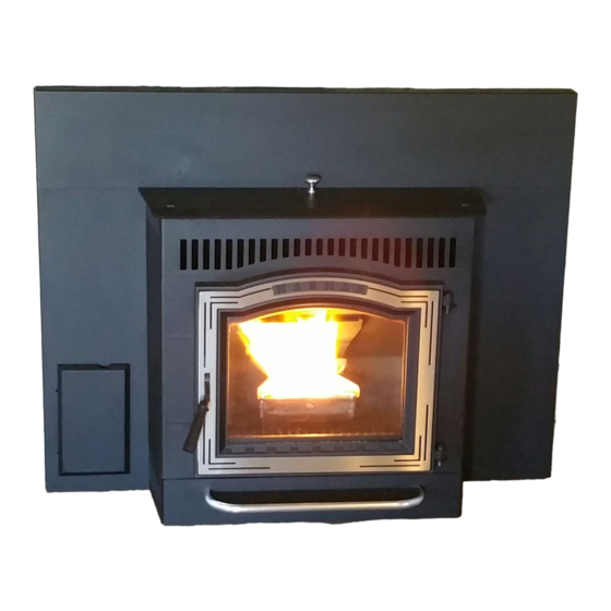
Model:
P35i
Pellet Fireplace Insert
#1-70-774195
#1-70-774235
Contact your local dealer with questions on
installation, operation or service.
•
Important operating
and maintenance
instructions included.
!
Please read this entire manual before
installation and use of this fireplace
insert room heater.
Failure to follow these instructions
could result in property damage, bodily
injury or even death.
• Do not store or use gasoline or other flammable vapors
and liquids in the vicinity of this or any other appliance.
• Do not overfire - If any external part starts to glow, you
are overfiring. Reduce feed rate. Overfiring will void
your warranty.
• Comply with all minimum clearances to combustibles
as specified. Failure to comply may cause a house fire.
!
Check building codes prior to installation.
• Installation MUST comply with local, regional, state
and national codes and regulations.
• Consult local building, fire officials or authorities
having jurisdiction about restrictions, installation
inspection, and permits.
NOTE:
To obtain a French translation of this manual, please contact your dealer or visit www.harmanstoves.com.
Pour obtenir une traduction française de ce manuel, s'il vous plaît contacter votre revendeur ou visitez www.harmanstoves.com.
Save These Instructions
SAVE THESE INSTRUCTIONS
•
Read, understand and
follow these instructions
for safe installation and
operation.
WARNING
CAUTION
SAVE THESE INSTRUCTIONS.
NOTICE
Hot, will cause burns.
•
Do not touch glass until it is cooled
•
NEVER allow children to touch glass
•
Keep children away
•
CAREFULLY SUPERVISE children in same room as
fireplace.
•
Alert children and adults to hazards of high temperatures.
High temperatures may ignite clothing or other
flammable materials.
• Keep clothing, furniture, draperies and other flammable
materials away.
Tested and approved for use with wood pellets only.
Burning any other type of fuel will void your warranty.
3-90-775R36_09/15
•
Leave this manual with
party responsible for
use and operation.
!
WARNING
HOT SURFACES!
Glass and other surfaces are
hot during operation AND cool
down.
!
CAUTION
www.harmanstoves.com
P35i
Use & Care Video
Advertisement
Table of Contents

Related Manuals for Harman P35i


Summary of Contents for Harman P35i
-
Page 1: Save These Instructions
SAVE THESE INSTRUCTIONS. Owner's Manual P35i Installation and Operation Use & Care Video Model: P35i Pellet Fireplace Insert #1-70-774195 #1-70-774235 Contact your local dealer with questions on installation, operation or service. NOTICE SAVE THESE INSTRUCTIONS • • • Read, understand and... -
Page 2: Table Of Contents
Safety Alert Key: • DANGER! Indicates a hazardous situation which, if not avoided will result in death or serious injury. • WARNING! Indicates a hazardous situation which, if not avoided could result in death or serious injury. • CAUTION! Indicates a hazardous situation which, if not avoided could result in minor or moderate injury. •... -
Page 3: Welcome
The P35i Pellet Insert has brilliant features in an elegant package, giving you up to 35,000 BTU when you need it, automatically. Aside from the regular, simple cleaning process, you need only set your desired room temperature, keep the hopper full, and the ash pan empty. With the P35i, you will notice even heat throughout your zone and a level of convenience you never thought possible. The P35i takes advantage of Harman 35+ years of stove design, technology and manufacturing. Output ® is managed by a microprocessor that senses the room temperature and the fire temperature with two thermistor probes and then determines the best feed rate for your heating demand. The platinum combination is Harman Patented Pellet Pro ® Feeder system, and ESP Control which have been developed to their highest state. These features work together to allow amazing heat output with little regard for fuel quality. We wish you and your family many years of enjoyment in the warmth and comfort of your hearth appliance. Thank you for choosing Harman ®... -
Page 4: Listing And Code Approvals
Method 28 & 5G Vent Size: 4 Inch Hopper Capacity: 41 Lbs (19-1/2" Hopper) 62 Lbs (23-1/2" Hopper) The P35i Pellet Insert is certified to Fuel Wood Pellet comply with 2015 particulate emission standards. Not approved for sale after * Weighted average LHV efficiency using data collected May 15, 2020. -
Page 5: Special Warnings And Notes
Special Warnings and Notes Carbon monoxide, referred to as CO, is a colorless, CO detectors are very sensitive and may sound an alarm odorless gas that is produced during combustion of solid for fumes other than CO or CO from sources other than fuels. CO is toxic and can be fatal. the stove such as a car or lawn mower exhaust. Even though this stove is designed to be as safe as If the alarm sounds possible, it is recommended that you install a CO detector. 1. -
Page 6: Getting Started
Getting Started A. Design, Installation & Location Considerations B. Fire Safety 1. Appliance Location Maintain the designated clearances to combustibles. Consideration must be given to safety, convenience, traffic Insulation must not touch the chimney. You must maintain the flow, and the fact that the appliance will need to be vented designated air space around the chimney. This space around to the outside. This appliance may only be installed into a chimney is necessary to allow natural heat removal from an existing masonry or manufactured wood-burning the area. -
Page 7: Component Locator
C. Component Locations Do Not allow finish materials to block the air flow through the return air slots. Hopper Lid Latch Viewing Glass Ash Pan Cover Door Latch Control Panel Return Air Slots Combustion Blower Exhaust Sensing Probe (ESP) Feed Motor Distribution Blower Pellet Pro Feeder Frame Latch Ash Pan Latch Save These Instructions... -
Page 8: Pre-Use Checklist
D. Pre- Use Check List WARNING Place the appliance in a location near the final installation and follow the procedures below. Inspect appliance and components for Open the appliance and remove all articles damage. Damaged parts may impair safe packed inside. Inspect all items for shipping operation. damage. Notify dealer of any missing or •... -
Page 9: Dimensions And Clearances
Dimensions and Clearances A. Appliance Dimensions 9-1/4” 235mm To Glass 24” 610mm Standard Surround Oversize Surround # 1-00-774221 # 1-00-774250 40" (1016mm) 46" (1168mm) 31" (787mm) 34" (864mm) 22” 559mm 14” 356mm 2” 50mm 8” 10” 203mm 254mm Save These Instructions 3-90-775R36_09/15... -
Page 10: Clearances To Combustibles
B. Clearances to Combustibles - Masonry or D. Minimum Opening for Masonry and Manufactured Fireplace Manufactured Fireplaces THE CLEARANCES SPECIFIED ARE FOR YOUR SAFETY! THESE CLEARANCES ONLY BE REDUCED BY MEANS APPROVED BY THE REGULATORY AUTHORITY. Mantel Face Trim Location Inches Millimeters Minimum Width 14-1/2 Minimum Depth... -
Page 11: Factory Built Fireplace
The factory built chimney must be listed per UL 127 (US) and meet type HT requirements of UL 103 (US). Factory When installing the P35i Insert into a factory built wood Built fireplace chimneys tested to UL 127-98 may be, at the burning fireplace, several things need to be taken into fireplace manufacturers option, tested to the same criteria consideration. -
Page 12: Vent Information
Chimney connector shall not pass through an attic or roof space, closet or Vent Information similar concealed space, or a floor or ceiling. A. Vent Termination Requirements Inside Corner Detail Fixed Porch or Deck Closed Openable Fixed Openable or Fixed Closed Openable Sidewalk =Vent Terminal =Air Supply Inlet =Area where termination is not permitted WARNING: Venting terminals must not be recessed into a I. -
Page 13: Avoiding Smoke And Odors
B. Avoiding Smoke and Odors Vent Configurations: To reduce probability of reverse drafting during shut- Negative Pressure, Shut-down, and Power Failure: down conditions, Hearth & Home Technologies strongly To reduce the probability of back-drafting or burn-back in recommends: the pellet burning appliance during power failure or shut- • Installing the pellet vent with a minimum vertical run of down conditions, the stove must be able to draft naturally five feet, preferably terminating above the roof line. -
Page 14: Venting Requirements & Restrictions
System Of This Appliance. longer the vent pipe and more elbows used in the system, the greater the flow resistance. DO NOT CONNECT THIS UNIT TO A CHIMNEY FLUE SERVING ANOTHER APPLIANCE. The recommended maximum flue lengths for the P35i Insert are as follows: WARNING! RISK OF FIRE! • Only LISTED type L or PL Pellet venting components 4" Flex Pipe: may be used. -
Page 15: Existing Fireplace Installation
D. Existing Fireplace Installation: Be sure to design the venting so that it can be easily cleaned. Check with your local authority having jurisdiction to When using a short run of venting (flex or rigid) the damper determine if this venting method is acceptable. Some must be removed or locked in the open position and sealed Provincial, State, or Local codes may require a full liner run with a plate constructed of steel or other non-combustible to the top of the chimney. Be sure and check your local material. -
Page 16: Rear Venting
E. Existing Fireplace, Rear Vent: The top of the chimney must also be sealed. Otherwise, it can become a nesting area or a water trap. NOTE: When installed in a rear vent configuration, the maximum BTU may be reduced due to elevated ESP temperatures associated with the horizontal exhaust stream. -
Page 17: Mobile Home - (Us Only)
Mobile Home A. Mobile Home Installation CAUTION Outside Air Kit #1-00-774280 Must be used for installation in a mobile home. Maintain structural integrity of mobile home: 1. An outside air inlet must be provided for combustion • Floor, wall, ceiling and/or roof. air, and must remain clear of leaves, debris, ice, and/or Do NOT cut through: snow. The outside air path must be unrestricted while •... -
Page 18: Appliance Set-Up
Appliance Set-Up A. Outside Air Attachment The image at left shows the use of the chimney for outside air supply. Also shown Outside Air Kit #1-00-774280 (sold separately) must be is the Chimney intake extension on the top of the chimney. It is slotted to allow fresh used for attaching outside air to the insert. This kit contains air into the flue. Be sure to use the proper a 3" stub and gasket to mount to the frame, and the outside... -
Page 19: Installing The Surround
B. Installing the Surround The surround consists of three panels, the top and two sides. Follow these steps for installation: 1. Remove the insert body from the mounting frame; 2. Start your leveling bolts into the floor of the frame and adjust to slightly raise the height. (see next section) This will allow some clearance to assemble the surround. 3. -
Page 20: Securing The Mounting Frame
D. Securing the Mounting Frame E. Attaching the Venting The mounting frame is the anchor for the appliance. If the frame is not secured properly, shifting will occur when sliding the insert in or out. The stove is supplied with a Leg Leveler Kit that contains (4) 5/16-18 X 1". These bolts should be threaded down through the holes to raise the frame corners as needed, to level. The mounting frame is the anchor for the appliance. If the frame is not secured properly, shifting will occur when sliding the insert in or out. -
Page 21: Installing The Body Into The Frame
F. Installing the Body into the Mounting Frame Attach the female terminal of the ground jumper wire to the ground lug on the air intake. The rollers on the sides of the insert body will ride on the rails of the mounting frame. Once the body is all the way in, hook and close the top spring latches on each side to secure. Room sensor placed here gives an accurate measure of return air. Push the pre-cut hole inward, and feed the sensor from the back side. Allow the bulb of the sensor to... -
Page 22: Flame Guide Extension
I. Flame Guide Extension K. Service Rail Kit- #1-00-774125 Once the flame guide is installed the Flame Guide Extension The Service Rail Kit is used to support the insert body should be installed by sliding it in behind the flame guide as while it is pulled out of the mounting frame for cleaning or shown below. Notice the bend points away from the Heat service. -
Page 23: Operating Instructions
Operating Instructions A. Fire Safety WARNING You can never be too cautious when it comes to fire safety. Please give serious consideration to the following: B U R N I N G C O L O R E D PA P E R , C A R D B O A R D , •... -
Page 24: General Operating Information
"Room Temp" Mode using the outer scale marked only. Requires special DDM in degrees Fahrenheit. It also allows you to adjust monitor supplied to Harman ® the stove temperature while in "Constant Burn" Dealers exclusively. - Page 25 Feed Limit Adjustment Temperature Dial The Circuit board runs on a one minute timer cycle. Each The temperature dial is a dual purpose dial. In Room-Temp minute, the board is thinking ahead to what it needs to do mode, you select the room temperature you want the stove for the next minute to maintain or achieve the demanded to maintain at the room sensor probe. This is marked in temperature. What you are setting on the Feed Limit dial is Fahrenheit scale from 50 to 90 degrees.
-
Page 26: Before Your First Fire
D. Before Your First Fire WARNING • Be sure the appliance is installed properly and that all safety requirements have been met. Pay particular TESTED AND APPROVED FOR USE WITH WOOD attention to the clearances to combustibles, floor PELLETS ONLY. USE OF ANY OTHER TYPE OF FUEL protection and the venting instructions. -
Page 27: Starting A Fire In "Automatic" Mode
Keep Hopper Lid, Ash Pan, and Fire viewing doors closed while in operation. Maintain all door seals and gaskets in good condition. Replace gaskets when necessary using parts obtained through your Harman ® dealer. G. Maintaining the Fire Once the Distribution Blower begins operation, your fire is well established. Now, you can make any desired... -
Page 28: Troubleshooting
With proper installation, operation, and maintenance, your appliance will provide years of trouble- free service. If you do experience a problem, this troubleshooting guide will assist a qualified service Troubleshooting person in proper diagnosis and repair. This guide is intended for qualified service technician use only. Error Message Possible Cause Corrective Action Broken, Wire or connection Check connection / Replace Probe 3-Blinks; Poor ESP Exhaust temperature has gone out of Clean exhaust - possible soot or creosote Signal range multiple times. accumulation near ESP. 4-Blinks; Poor room Broken Sensor, wire or connection Check connections / Replace sensor sensor signal No fuel in hopper Add fuel Door, hopper lid, or ash pan open Close all doors and check seals Perform draft test, clean exhaust, replace blower Poor draft / weak combustion blower... -
Page 29: Service & Maintenance
Service & Maintenance A. Shut-down Procedure Soot- Formation and Need For Removal- When wood is burned, the products of combustion combine with moisture The best way to shut down the appliance is to simply let it to form a soot residue which accumulates on the flue lining. run out of fuel, and shut down naturally as the temperature When ignited, this soot makes an extremely hot fire. The cools. -
Page 30: General Maintenance Procedure
C. General Maintenance Procedures 2. Ash Removal From Firebox • Frequency: Weekly / depending on fuel and/or ash 1. Burn Pot Grate Cleaning buildup. • Frequency: Daily to Weekly * • By: User • By: User Wear Leather Gloves To Perform Wear Leather Gloves To Prevent Skin Burns! The fire MUST be out and cool for safe ash removal. - Page 31 WARNING! RISK OF FIRE! Keep combustible materials, 5. Cleaning Heat Exchanger & Exhaust gasoline and other flammable vapors and liquids clear of • Frequency: Monthly or after each ton of fuel is burned. the appliance. • By: User • Do NOT store flammable materials in the vicinity of the appliance.
- Page 32 d. Un-latch and remove the ash pan. Dispose of the ashes k. With this cover removed, you can vacuum the paddle fan in a metal container with a tight fitting lid. and the inside of the chamber. Be careful not to bend the blades on the paddle fan. e. Remove the two (2) corner cleanout covers by removing the wing-screws (one per). Right & Left Corner Exhaust Chamber Cleanout Covers Access Cover l. Before reinstalling the access cover, make sure the f. Brush or vacuum the remaining ash from the firebox.
- Page 33 During periods of incomplete combustion, which may occur needed. Do not operate the stove with a broken glass. during start-up, shut down, or when operated incorrectly, Replacement glass, which is mirrored ceramic glass, should the fly ash may actually lead to soot formation in the venting be obtained through your Harman dealer. system. ® To replace a broken glass; first be sure to carefully remove The venting system will need to be cleaned at least once the broken glass and any remaining shards or pieces. With...
-
Page 34: Motors & Components
D. Motors & Components Hopper Lid Latch Viewing Glass Ash Pan Cover Door Latch Control Panel Return Air Slots Combustion Blower Exhaust Sensing Probe (ESP) Feed Motor Distribution Blower Pellet Pro Feeder Ash Pan Latch Frame Latch 3-90-775R36_09/15 Save These Instructions... - Page 35 1. Feed Motor Requires no lubrication. Keep the motor windings free of dust. Can be wiped clean or vacuumed. To remove feed motor: • Slide the insert body out of the mounting frame. • Between the feed motor and the feeder body, you'll see the cam block with a bearing that actuates the pusher arm.
- Page 36 4. Distribution Blower Requires no lubrication. Keep the motor windings and squirrel cage fan free of dust. Can be wiped clean or vacuumed. To remove distribution blower: • Slide the insert body out of the mounting frame. • Locate the blower in the back of the unit. You'll need to tilt the unit forward for easy access. •...
- Page 37 6. Igniter Vacuum to clean. Whenever cleaning burn pot air chamber. To remove igniter: • Loosen wing screws and remove cover on front of burn pot. • Using a 5/16" wrench, remove the two black screws above the cleanout. The igniter and bracket are now free.
-
Page 38: Reference Materials
Reference Materials A. Wiring Diagram 3-90-775R36_09/15 Save These Instructions... -
Page 39: Loss Of Power
® available online or at computer and office equipment stores. automatic ignition system. This is the safest and most Your Harman® appliance with Rev E or later software reliable way for igniting the unit. In the event the automatic available beginning in November 2010 may be plugged igniter is not functioning, the steps below may be followed directly into a Harman®... -
Page 40: Service Parts Lists
D. Service Parts List P35i Pellet Insert Service Parts Beginning Manufacturing Date: July 2010 Pellet Insert Ending Manufacturing Date: Active (23.5 in)1-70-774235-1 (Black), (19.5 in)1-70-774195-1 (Black), Ending Manufacturing Date: June 2011 (23.5 in) 1-70-774235-2 (Charcoal), 1-70-774235-3 (Golden re)) (19.5 in) 1-70-774195-2 (Charcoal), 1-70-774195-3 (Golden re)) IMPORTANT: THIS IS DATED INFORMATION. -
Page 41: Service Parts
P35i Pellet Insert Service Parts Beginning Manufacturing Date: July 2010 Ending Manufacturing Date: Active #4 Surround Assembly IMPORTANT: THIS IS DATED INFORMATION. Parts must be ordered from a dealer or distributor. Stocked Hearth and Home Technologies does not sell directly to consumers. Provide model number and serial number when requesting service parts from your dealer or distributor. - Page 42 P35i Pellet Insert Service Parts Beginning Manufacturing Date: July 2010 Ending Manufacturing Date: Active IMPORTANT: THIS IS DATED INFORMATION. Parts must be ordered from a dealer or distributor. Stocked Hearth and Home Technologies does not sell directly to consumers. Provide model number and serial number when requesting service parts from your dealer or distributor.
- Page 43 P35i Pellet Insert Service Parts Beginning Manufacturing Date: July 2010 Ending Manufacturing Date: Active IMPORTANT: THIS IS DATED INFORMATION. Parts must be ordered from a dealer or distributor. Stocked Hearth and Home Technologies does not sell directly to consumers. Provide model number and serial number when requesting service parts from your dealer or distributor.
-
Page 44: Custom Surround Sizes
P35i Pellet Insert Service Parts Beginning Manufacturing Date: July 2010 Ending Manufacturing Date: Active #27 Feeder Assembly 27.1 27.8 27.6 27.2 27.3 27.9 27.10 27.7 27.4 27.5 27.20 27.19 27.18 27.11 27.13 27.17 27.12 27.16 27.14 27.15 IMPORTANT: THIS IS DATED INFORMATION. Parts must be ordered from a dealer or distributor. - Page 45 E. Custom Size Surround This diagram shows the minimum dimensions of a custom fit surround panel, part number 1-00-774221-SPL. Note that arched surrounds can only be made flat. Therefore, the intake air slots, normally in the sides of the surround, are moved to the face. Rectangular surrounds can be made flat if desired, and they will also have the intake slots in the face. P35i Custom Surround The top of the mounting frame must be covered at this point. Part #: 1-00-774221-SPL Arched - Minimum Center Height Rectangular Minimum Height Arched - Minimum 31-3/8”...
-
Page 46: Warranty Policy
F. Warranty Policy Hearth & Home Technologies LIMITED LIFETIME WARRANTY Hearth & Home Technologies, on behalf of its hearth brands (”HHT”), extends the following warranty for HHT gas, wood, pellet, coal and electric hearth appliances that are purchased from an HHT authorized dealer. WARRANTY COVERAGE: HHT warrants to the original owner of the HHT appliance at the site of installation, and to any transferee taking ownership of the appliance at the site of installation within two years following the date of original purchase, that the HHT appliance will be free from defects in materials and workmanship at the time of manufacture. After installation, if covered compo- nents manufactured by HHT are found to be defective in materials or workmanship during the applicable warranty period, HHT will, at its option, repair or replace the covered components. - Page 47 WARRANTY CONDITIONS: • This warranty only covers HHT appliances that are purchased through an HHT authorized dealer or distributor. A list of HHT authorized dealers is available on the HHT branded websites. • This warranty is only valid while the HHT appliance remains at the site of original installation. •...
- Page 48 Service & Maintenance Log Date Of Service Performed By Description Of Service Save These Instructions 3-90-775R36_09/15...
- Page 49 Save These Instructions 3-90-775R36_09/15...
- Page 50 352 Mountain House Road, Halifax, PA 17032 www.harmanstoves.com Please contact your Harman dealer with any questions or concerns. ® For the location of your nearest Harman dealer, ® please visit www.harmanstoves.com. - NOTES - ________________________________________________________________________________ ________________________________________________________________________________ ________________________________________________________________________________ ________________________________________________________________________________ ________________________________________________________________________________ ________________________________________________________________________________ ________________________________________________________________________________ ________________________________________________________________________________ ________________________________________________________________________________ NOTICE DO NOT DISCARD THIS MANUAL •...
Need help?
Do you have a question about the P35i and is the answer not in the manual?
Questions and answers