Table of Contents
Advertisement
Operator's Manual
FLEXTEC
Register your machine:
www.lincolnelectric.com/register
Authorized Service and Distributor Locator:
www.lincolnelectric.com/locator
Save for future reference
Date Purchased
Code: (ex: 10859)
Serial: (ex: U1060512345)
IM10194
| Issue D ate 10 /14
© Lincoln Global, Inc. All Rights Reserved.
™
500 P
For use with machines having Code Numbers:
12246
Advertisement
Table of Contents
Troubleshooting

Related Manuals for Lincoln Electric FLEXTEC 500 P


Summary of Contents for Lincoln Electric FLEXTEC 500 P
- Page 1 Operator’s Manual ™ FLEXTEC 500 P For use with machines having Code Numbers: 12246 Register your machine: www.lincolnelectric.com/register Authorized Service and Distributor Locator: www.lincolnelectric.com/locator Save for future reference Date Purchased Code: (ex: 10859) Serial: (ex: U1060512345) IM10194 | Issue D ate 10 /14 ©...
- Page 2 THANK YOU FOR SELECTING A QUALITY PRODUCT BY KeeP your head out oF the Fumes. LINCOLN ELEC TRIC. DON’T get too close to the arc. Use corrective lenses if necessary to stay a reasonable distance away from the arc. READ and obey the Material Safety Please examine Carton and equiPment For Data Sheet (MSDS) and the warning damage immediately...
- Page 3 American Welding Society, P.O. Box 351040, Miami, Florida 33135 or ELECTRIC AND CSA Standard W117.2-1974. A Free copy of “Arc Welding Safety” MAGNETIC FIELDS MAY booklet E205 is available from the Lincoln Electric Company, 22801 BE DANGEROUS St. Clair Avenue, Cleveland, Ohio 44117-1199. BE SURE THAT ALL INSTALLATION, OPERATION, MAINTENANCE AND REPAIR PROCEDURES ARE 2.a.
-
Page 4: Electric Shock Can Kill
SAFETY ELECTRIC SHOCK ARC RAYS CAN BURN. CAN KILL. 3.a. The electrode and work (or ground) circuits are 4.a. Use a shield with the proper filter and cover plates to protect your electrically “hot” when the welder is on. Do eyes from sparks and the rays of the arc when welding or not touch these “hot”... - Page 5 SAFETY WELDING AND CUTTING CYLINDER MAY EXPLODE IF SPARKS CAN CAUSE DAMAGED. FIRE OR EXPLOSION. 7.a. Use only compressed gas cylinders containing the correct shielding gas for the process used 6.a. Remove fire hazards from the welding area. If and properly operating regulators designed for this is not possible, cover them to prevent the welding sparks the gas and pressure used.
- Page 6 FLEXTEC™ 500 P TABLE OF CONTENTS...
- Page 7 FLEXTEC™ 500 P TABLE OF CONTENTS...
- Page 8 FLEXTEC™ 500 P CHANGES AFTER INITIAL RELEASE CHANGES AFTER INITIAL RELEASE...
-
Page 9: Product Description
PRODUCT DESCRIPTION PRODUCT DESCRIPTION Product Summary The Flextec™ 500 P is a multi-process CC/CV/Pulse DC inverter power source rated for 450 Amps, 38 Volts at 100% duty cycle. The Flextec™ 500 P comes in a rugged case and is intended for either indoor or outdoor operation and comes with an IP23 environmental rating. -
Page 10: Recommended Processes And Equipment
NR-203; NR-211, STEEL NR-440NI2 PROCESS LIMITATIONS The Flextec 500 P is suitable only for the processes listed. EQUIPMENT LIMITATIONS Operating Temperature Range is -10° C to + 55° C. Output is de-rated for temperatures in excess of 40° C. OUTPUT RATINGS AT 40° C... - Page 11 FLEXTEC™ 500 P PRODUCT DESCRIPTION COMMON OPTIONAL KITS & ACCESSORIES K3059-2 INVERTER CART K3056-1 BASE MOUNTING KIT K3091-1 MULTI-PROCESS SWITCH K2909-1 12-PIN TO 6-PIN ADAPTER K3127-1 WIRELESS FOOT PEDAL K857-2 REMOTE OUTPUT CONTROL WITH 12-PIN UNIVERSAL CONNECTOR (25 FEET) K870-2 FOOT AMPTROL K963-3 HAND AMPTROL...
- Page 12 FLEXTEC™ 500 P NOTES...
-
Page 13: Technical Specifications
FLEXTEC™ 500 P DESIGN DESIGN TECHNICAL SPECIFICATIONS POWER SOURCES - INPUT VOLTAGE AND CURRENT MODEL DUTY CYCLE INPUT VOLTAGE ± 10% INPUT AMPERES IDLE POWER (W) POWER FACTOR K4092-1 60% RATING 380 / 460 / 575 / 3 / 50 / 60 39 / 32 / 32 150W FAN ON 100% RATING... -
Page 14: Design Features
FLEXTEC™ 500 P DESIGN AGENCY APPROVALS MODEL MARKET CONFORMITY MARK NOTES K4092-1 US AND CANADA C/US AUSTRALIA C-TICK REQUIRES K3975-1 EUROPE CE FILTER KIT DESIGN FEATURES • Pulse Modes – for demanding applications that require low heat • The Future is Now – You no longer have to pay a price premium input and reduced spatter to gain the advantages of inverter technology over conventional welders. -
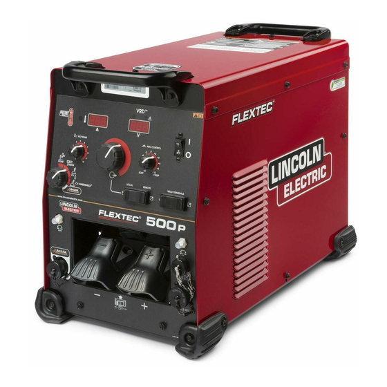
Page 15: Case Front Controls
FLEXTEC™ 500 P DESIGN CASE FRONT CONTROLS 8. Local/Remote Selector Toggle Switch: CASE FRONT CONTROLS DESCRIPTIONS. Sets the control of the output to local (output control knob) or remote (K857 hand amptrol or K870 foot amptrol through the 12- pin or 14-pin circular connectors). 1. -
Page 16: Case Back Controls
FLEXTEC™ 500 P DESIGN CASE BACK CONTROLS CASE BACK CONTROLS DESCRIPTIONS. 1. Input Power Cord Access Hole 2. Access Panel – Allows access for connecting input power and configuring the machine 3. Input Power Reconnect – Configures the machine for the input supply voltage 4. -
Page 17: Internal Controls
FLEXTEC™ 500 P DESIGN INTERNAL CONTROLS Internal Controls Description The User Interface pc board has one bank of dip switches (See Figure A.1). As shipped from the factory and under normal conditions, the dip switches are all in the ‘off’ position (Figure A.2). There are 2 instances that require a change of the dip switch. - Page 18 FLEXTEC™ 500 P INSTALLATION INSTALLATION WARNING ELECTRIC SHOCK CAN KILL. ONLY QUALIFIED PERSONNEL SHOULD PERFORM THIS INSTALLATION. • TURN OFF INPUT POWER TO THE POWER SOURCE AT THE DISCONNECT SWITCH OR FUSE BOX BEFORE WORKING ON THIS EQUIPMENT. TURN OFF THE INPUT POWER TO ANY OTHER EQUIPMENT CONNECTED TO THE WELDING SYSTEM AT THE DISCONNECT SWITCH OR FUSE BOX BEFORE...
- Page 19 FLEXTEC™ 500 P INSTALLATION Use a three-phase supply line. A 1.75 inch (45 mm) diameter access hole for the input supply is located on the case back. Remove the reconnect access panel located on the case back and connect L1, L2, L3 and ground according to the Input Supply Connection Diagram decal.
-
Page 20: Input Voltage Selection
FLEXTEC™ 500 P INSTALLATION INPUT VOLTAGE SELECTION Welders are shipped connected for 460V input voltage. If the Auxiliary lead (indicated as ‘A’) is placed in the wrong position and power is applied to the machine, the machine will protect itself and display an error message: •... - Page 21 FLEXTEC™ 500 P INSTALLATION CONNECTION DIAGRAMS, CONTROL CABLES Analog Wire Feeder Connectivity Picture Function Wiring 14-pin Ground connector for Trigger, Common wire feeder Trigger input connectivity. 77 Remote potentiometer, 10V 76 Remote potentiometer, wiper 75 Remote potentiometer, common Work (21) 42 VAC 42 VAC...
- Page 22 FLEXTEC™ 500 P INSTALLATION ArcLink Wire Feeder & Digital Accessory Connectivity Picture Function Wiring ArcLink CAN 5-pin ArcLink CAN connector for Electrode Sense Lead wire feeder 40Vdc connectivity. 40Vdc Common Picture Function Wiring ArcLink CAN ArcLink CAN Remote Potentiometer Common 12-pin remote Remote Potentiometer Wiper control...
- Page 23 FLEXTEC™ 500 P INSTALLATION • Route all cables directly to the work and wire feeder, avoid RECOMMENDED ELECTRODE AND WORK excessive lengths and do not coil excess cable. Route the CABLE SIZES FOR ARC WELDING electrode and work cables in close proximity to one another to General Guidelines minimize the loop area and therefore the inductance of the weld circuit.
-
Page 24: Electrode Voltage Sensing
FLEXTEC™ 500 P INSTALLATION CONTROL CABLE AND VOLTAGE SENSING CONNECTIONS Electrode Voltage Sensing General Guidelines The remote ELECTRODE sense lead (67) is built into the 5-pin ArcLink Genuine Lincoln control cables should be used at all times (except control cable (K1543-xx) and is always connected to the wire drive where noted otherwise). - Page 25 Figure B2, and set the output control of each power sources to one half of the desired arc current. Figure B.2 INPUT LINES INPUT TERMINAL BLOCK TO GROUND PER NATIONAL FLEXTEC 500 P ELECTRICAL CODE (MACHINE #1) NEGATIVE POSITIVE INPUT LINES INPUT TERMINAL BLOCK...
- Page 26 FLEXTEC™ 500 P NOTES...
- Page 27 FLEXTEC™ 500 P OPERATION OPERATION GRAPHIC SYMBOLS THAT APPEAR ON THIS MACHINE OR IN THIS MANUAL RATED REDUCED INPUT POWER NO-LOAD VOLTAGE OPEN CIRCUIT VOLTAGE INPUT VOLTAGE OUTPUT VOLTAGE HIGH TEMPERATURE INPUT CURRENT MACHINE STATUS CIRCUIT BREAKER OUTPUT CURRENT PROTECTIVE WIRE FEEDER GROUND POSITIVE OUTPUT...
- Page 28 FLEXTEC™ 500 P OPERATION POWER-UP SEQUENCE WARNING ELECTRIC SHOCK can kill. UNLESS USING COLD FEED FEATURE, WHEN FEEDING WITH GUN TRIGGER, THE ELEC- TRODE AND DRIVE MECHANISM ARE ALWAYS ELECTRICALLY ENERGIZED AND COULD REMAIN ENERGIZED SEVERAL SECONDS AFTER THE WELDING CEASES. -------------------------------------------------------- FUMES AND GASES can be dangerous to your health.
-
Page 29: Duty Cycle
FLEXTEC™ 500 P OPERATION DUTY CYCLE DEFINITION OF WELDING MODES NON-SYNERGIC WELDING MODES The Flextec™ 500 P is capable of welding at a 100% duty cycle (continuous welding) at 450 Amps rated output. • A Non-synergic welding mode requires all welding process The 60% duty cycle rating is 500 amps (based off of a ten minute variables to be set by the operator. - Page 30 FLEXTEC™ 500 P OPERATION Output Control Dial Control - Local/Remote Toggle Switch Output control is conducted via a single turn potentiometer. • Set the switch to ‘local’ to control output at the Flextec™ via the Adjustment is indicated by the meters. Output Control dial.
-
Page 31: Smaw
FLEXTEC™ 500 P OPERATION • When the Local/Remote is set to Remote, this dial sets the BASIC MODES OF OPERATION maximum welding amperage. The remote potentiometer than controls the amperage from minimum to this pre-set maximum. SMAW This weld mode is a constant current (CC) mode featuring continuous control from 15 –... - Page 32 FLEXTEC™ 500 P OPERATION GTAW This weld mode is a constant current (CC) mode featuring continuous control from 10 –500 amps. It is intended for the GTAW TIG welding processes. Hot Start - Hot start regulates the arc initiation current. A setting of +10 results in the most positive arc initiation.
-
Page 33: Cv-Gas
FLEXTEC™ 500 P OPERATION CV-GAS This weld mode is a constant voltage (CV) mode featuring continuous control from 10 to 45 volts. It is intended for the GMAW, FCAW-GS, MCAW welding processes and arc gouging. Hot Start – Rotate from the ‘0’ position to the ‘10’ position to provide more energy during the start of a weld. - Page 34 FLEXTEC™ 500 P OPERATION CV-INNERSHIELD This weld mode is a constant voltage (CV) mode featuring continuous control from 10 to 45 volts. It is intended for the FCAW-SS welding process and arc gouging. Hot Start – Toggle from the ‘0’ position to the ‘10’ position to provide more energy during the start of a weld.
- Page 35 FLEXTEC™ 500 P OPERATION ARCLINK This weld mode is intended to unlock basic non-synergic, synergic and pulse modes intended for use with a compatible ArcLink wire feeders. All of the Flextec™ 500 P user interface controls are disabled in this mode and controlling the power source is accomplished from the wire feeder user interface.
-
Page 36: Pulse Welding In Arclink Mode
FLEXTEC™ 500 P OPERATION PULSE WELDING IN ARCLINK MODE Pulse welding procedures are set by controlling an overall “arc length” variable. When pulse welding, the arc voltage is highly dependent upon the waveform. The peak current, back ground current, rise time, fall time and pulse frequency all affect the voltage. The exact voltage for a given wire feed speed can only be predicted when all the pulsing waveform parameters are known. - Page 37 For additional information about UltimArc Arc Controls and pulse welding procedure Lincoln Electric publishes process documents as informational guides on various welding procedures. Access to the process documents can be attained at the following web address: http://www.lincolnelectric.com/en-us/equipment/advanced-process-...
- Page 38 DC welding power source and the work clamp. Weld Fume Control Solutions. Lincoln Electric offers a wide variety of welding fume control solutions, ranging from portable systems easily wheeled around the shop to shop-wide central systems servicing many dedicated welding stations.
-
Page 39: Periodic Maintenance
FLEXTEC™ 500 P MAINTENANCE MAINTENANCE PERIODIC MAINTENANCE WARNING Thermal Protection Thermostats protect the machine from excessive operating temperatures. Excessive temperatures may be caused by a lack of ELECTRIC SHOCK can kill. cooling air or operating the machine beyond the duty cycle and output •... -
Page 40: Troubleshooting
HOW TO USE TROUBLESHOOTING GUIDE WARNING Service and Repair should only be performed by Lincoln Electric Factory Trained Personnel. Unauthorized repairs performed on this equipment may result in danger to the technician and machine operator and will invalidate your factory warranty. -
Page 41: Error Codes
FLEXTEC™ 500 P TROUBLE SHOOTING ERROR CODES The status lights on the User Interface board and the Switch board are Errors are displayed on the user interface. In addition, there are status dual-color LED’s. Normal operation for each is steady green. lights on the User Interface PC board and the Switch PC board that contain error sequences. - Page 42 COURSE OF ACTION Major physical or electrical damage 1. Contact your local authorized is evident when the sheet metal Lincoln Electric Field Service facility covers are removed. for technical assistance. Machine won’t weld, can’t get any 1. If the displays show an Err ### output.
-
Page 43: Diagrams
FLEXTEC™ 500 P DIAGRAMS FRONT OF MACHINE ~575V ~42V ~460V ~380V ~52V ~115V H3... - Page 44 FLEXTEC™ 500 P DIAGRAMS...
- Page 45 FLEXTEC™ 500 P DIAGRAMS...
- Page 46 FLEXTEC™ 500 P DIAGRAMS...
- Page 47 FLEXTEC™ 500 P DIAGRAMS...
- Page 48 FLEXTEC™ 500 P DIAGRAMS...
- Page 49 FLEXTEC™ 500 P DIAGRAMS...
- Page 50 Lincoln Electric for advice or information about their use of our products. We respond to our customers based on the best information in our possession at that time. Lincoln Electric is not in a position to warrant or guarantee such advice, and assumes no liability, with respect to such information or advice.
Need help?
Do you have a question about the FLEXTEC 500 P and is the answer not in the manual?
Questions and answers