Table of Contents
Advertisement
Advertisement
Table of Contents

Related Manuals for S.E.P. SUPER SMART

Summary of Contents for S.E.P. SUPER SMART
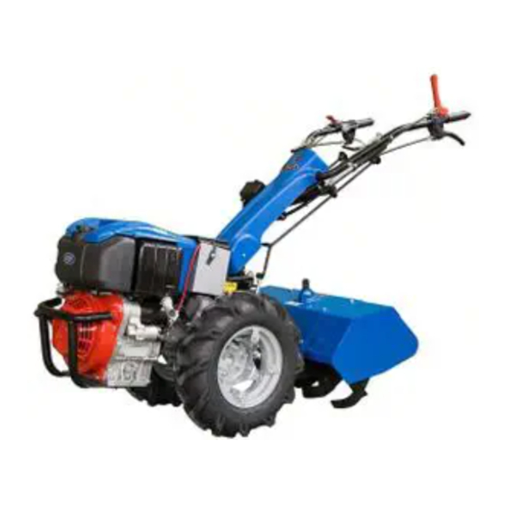
- Page 1 USE AND MAINTENANCE MANUAL SUPER SMART SUPER SMART Diesel ®...
- Page 3 REVERSIBLE TWO-WHEEL TRACTOR SUPER SMART SUPER SMART Diesel BEFORE USING THE TWO-WHEEL TRACTOR CAREFULLY READ THE INSTRUCTIONS GIVEN IN THIS MANUAL...
-
Page 4: Table Of Contents
TABLE OF CONTENTS Page Page INTRODUCTION............ 3 OPERATING THE TWO-WHEEL TRACTOR..12 STARTING THE ENGINE........12 SAFETY REGULATIONS ........3 STOPPING THE ENGINE ........12 GENERAL NOTICES..........3 STARTING THE ENGINE ........4 FITTING FRONT-MOUNTED ATTACHMENTS ............. 13 OPERATING OF THE TWO-WHEEL TRACTOR ... 4 SAFETY DEVICE .......... -
Page 5: Introduction
− model SUPER SMART going to press. Manufacturer reserves the right to in the versions with gasoline engine. modify this document at any time without prior no- tice. -
Page 6: Starting The Engine
• Before using an attachment, make sure that the reverse speed safety device has been set as re- STARTING THE ENGINE quired (this can be used when the front-mounted • Disengage all control levers before starting the mo- attachments are fitted, and not when the tiller is ro- tor. -
Page 7: Identification Data
• Keep your two-wheel tractor clean. Do not let grass IDENTIFICATION DATA and oil residues build up: these are a fire hazard. • Fuel is highly flammable. Store fuel only in spe- TWO-WHEEL TRACTOR IDENTIFICATION cifically designed containers. Refuel your two- The serial number is stamped on the engine side of wheel tractor in the open. - Page 8 3.50-6 Anno di Fabbricazione: with rotary tiller cm. 50 Massa: 83,500 NOTE: SUPER SMART Diesel model does not allow the use of front attachment. S/N reading: BH10 type of machine year of manufacturing 000 week of production progressiv n° of production...
-
Page 9: Technical Specifications
TECHNICAL SPECIFICATIONS ENGINE installation of the attachments, and does not require the use of bolts, nuts or spanner. The two-wheel tractor may be fitted with the following HANDLEBARS engines: Adjustable in height and width. Rotate handlebars − HONDA GC 160; 4 stroke gasoline engine; through 180 when front-mounted attachments are 3,7 kW (5 CV);... -
Page 10: Safety Devices
TWO-WHEEL TRACTOR 1450 370 ÷ 400 MOTOR-MOWER 370 ÷ 400 1500 950 ÷ 960 SAFETY DEVICES The two-wheel tractor is fitted with the following safety devices to ensure maximum safety: − Automatic PTO disengagement device. This is a mechanical device that prevents shift into reverse speed when the PTO is rotating (motor-mower configuration only). -
Page 11: Transfer Printing - Instructions And Safety
TRANSFER PRINTING - For accident prevention purposes, they must always be clearly readable. Should they be damaged, it is INSTRUCTIONS AND SAFETY compulsory to replace them by requesting the origi- nal spare part from the Manufacturer. Please find below the adhesive transfer printing shown on the machine. -
Page 12: Two-Wheel Tractor Controls
TWO-WHEEL TRACTOR CONTROLS See fig.4. Throttle control lever. Clutch lever. Attachments instant adaptor. Engine stop lever. Gear lever. (Note 2) NOTE 1: When the machine is fitted with front- mounted attachments, this lever becomes Handlebar vertical lock release lever. the gear lever. Handlebar sideway lock release lever. -
Page 13: Controls Of Front-Mounted Attachments
Handlebar vertical lock release lever WARNING (See fig. 4, item 4) A safety device does not permit reverse speed to be engaged when the PTO is operating (rotary tilling) This allows the handle to be vertically adjusted to suit driving comfort and tilling depth. Power Take Off (PTO) control lever (two- Simply push down lever (1) to release handles. -
Page 14: Operating The Two-Wheel Tractor
with respect to when the machine is used as a motor- g. Turn throttle lever (4) for 1/4 turn. mower. h. Grip the pull-rope handle and pull firmly and This is due to reversal of the direction of motion. quickly. When the engine starts, allow the rope to Lever (fig. -
Page 15: Fitting Front-Mounted Attachments
CAUTION SUPER SMART Diesel model does not allow the use of front attachment. SAFETY DEVICE Set the reverse speed safety device in the correct po- sition as regards the direction of travel (see fig. -
Page 16: Coupling Attachments To The Pto
COUPLING ATTACHMENTS TO Every 20 hours Check the oil level in the gearbox housing: to do this, THE PTO slacken the screw (2) and check that oil is coming out from the screw position. The PTO is fitted with an instant adaptor device to fit attachments quickly and easily. -
Page 17: Checks And Adjustments
CHECKS AND ADJUSTMENTS CLUTCH LEVER The clutch lever must have a free play of about 5 to 6 mm before the clutch starts to disengage. Insufficient play can cause clutch slip, while excess play can lead to failure to disengage fully. Adjust play by means of cable adjuster (see fig. -
Page 18: Rotary Tiller
ROTARY TILLER WARNING • Do not use the rotary tiller without the hood. • Do not proceed to tilling in proximity of children and/or animals. • Keep your hands and feet clear of the tiller at- tachment when the motor is running. Stop the en- gine before touching the tiller for any reason. - Page 19 each tilling element, and by removing or adding one tiller rotor at the end of the two tillers. Refer to fig. 2 to determine the tiller rotor configura- tion required to obtain the desired tilling width, then proceed as follows. Tilling depth adjustment To vary tilling depth you must adjust the height of rear tine (fig.
-
Page 20: Rotary Tiller Maintenance
ROTARY TILLER MAINTENANCE After the first 50 hours (running in) a. Check that all nuts and bolts are secure. Tighten if necessary. b. Change the oil in the tiller drive unit as follows. Remove plug (fig. 6, item 1) and turn the attach- ment upside down to drain out the exhausted oil. -
Page 21: Cutter Bar Mower
CUTTER BAR MOWER WARNING • When you transport your machine, and when you finish work, always fit the knife guard over the cut- ter bar. • Keep your hands and feet clear of the cutter bar when in motion. • Do not operate the mower in proximity of children and/or animals. -
Page 22: Cutter Bar Mower Technical Specifications
CUTTER BAR MOWER TECHNICAL b. Loosen lock nut (5) and turn wear plate adjuster screw (4) to obtain correct sliding movement of SPECIFICATIONS the knife. Mechanical con-rod drive c. Tighten again the securing nut (5) and the screws (1) and (2). −... -
Page 23: Cutter Bar Mower Maintenance
Cutting height adjustment CUTTER BAR MOWERS MAINTENANCE Proceed as follows to adjust cutting height.(fig.3) MECHANICAL CON-ROD DRIVE a. Loosen the two nuts (1) and (2) that secure each Lubrication of the two support slides After the first 5 hours of work, and subsequently af- b. -
Page 27: Ec Certificate Of Conformity
42018 SAN MARTINO IN RIO (RE) ITALY Declare on their own responsibility, that the machine TWO-WHEEL TRACTOR with rotary tiller and/or sickle bar mower Brand: S.E.P. Type: SUPER SMART from machine serial n° BH10X00000 from machine chassis n° A211408 A212096* from machine chassis n°... - Page 28 VALPADANA S.p.A. ® Società unipersonale appartenente al Gruppo Industriale Argo S.p.A. 42018 S. MARTINO IN RIO (RE) ITALY Via Don Pasquino Borghi, 6 TEL. 0522 73.17.11 - FAX 0522 73.17.31 E-MAIL: infosep@sep.it - http://www.sep.it...
Need help?
Do you have a question about the SUPER SMART and is the answer not in the manual?
Questions and answers